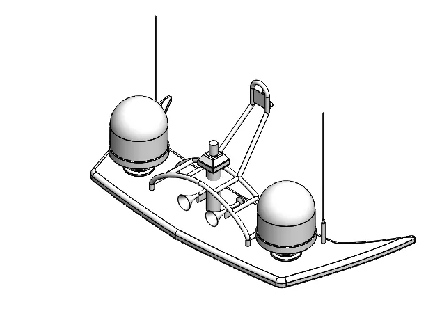
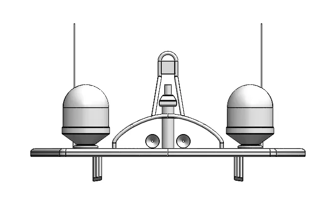
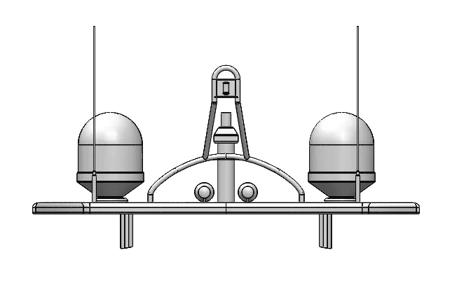
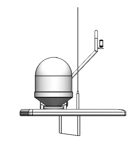
Radar Mast & Final Assembly of Yacht
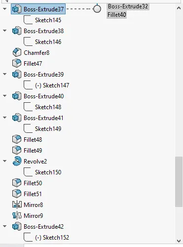
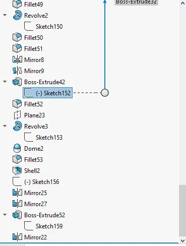
INTRODUCTION
SolidWorks is a solid modelling computer-aided design (CAD) and computer-aided engineering (CAE) computer program published by Dassault Systèmes. SolidWorks is a solid modeller, and utilizes a parametric feature-based approach which was initially developed by PTC (Creo/Pro-Engineer) to create models and assemblies. Parameters refer to constraints whose values determine the shape or geometry of the model or assembly. Parameters can be either numeric parameters, such as line lengths or circle diameters, or geometric parameters, such as tangent, parallel, concentric, horizontal or vertical, etc. Numeric parameters can be associated with each other through the use of relations, which allows them to capture design intent. In this project we learnt about the detailed design of sunseeker yatch parts and assembling. Sunseeker International is a British luxury performance motor yacht brand. Originally named Poole Power Boats, the company was founded by brothers Robert and John Braithwaite in 1969. The company changed its name to Sunseeker International in 1985 and has since become a global icon. Its headquarters and main assembly facility is in Poole Harbour.
Objective:
- To create individual parts of the super yatch using solidworks according to dimensions.
- To assemble the parts into a yatch.
- To know how to use photoview 360 to render a product and make it more realistic and attractive.
RADAR:
Marine radars are X band or S band radars on ships, used to detect other ships and land obstacles, to provide bearing and distance for collision avoidance and navigation at sea. ... Radar is a vital navigation component for safety at sea and near the shore.
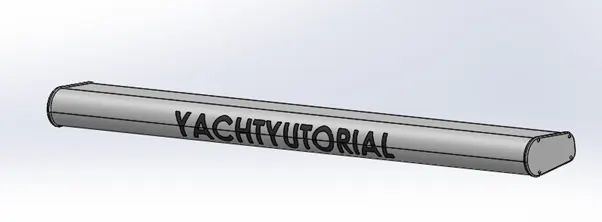
Features used to create kickstand:
- Sketch
- Extrude boss
- Fillet
- Extrude cut
- Sketch pattern
- Mirror
SKETCH:
When you open a new part document, first you create a sketch. The sketch is the basis for a 3D model.
EXTRUDE BOSS/BASE:
An Extruded Boss/Base feature will allow you to take a 2D sketch and add thickness to it in the third dimension.
FILLET:
Fillet/Round creates a rounded internal or external face on the part. You can fillet all edges of a face, selected sets of faces, selected edges, or edge loops.
EXTRUDE CUT:
You can use the Extrude tool to remove material by projecting a sketched section normal to the sketching plane.
Procedure followed to create a model of:
- Open solidworks and create a part file
- Create a blueprint for the further construction.
- Before creating the sketch change the default planes as follows:
- Front plane- Front plane
- Top plane - top plane
- Select front plane start the sketch.
- Then 2D sketch is created in the front plane and dimensions are given and sketch is fully defined.
- Fillets are given to smoothen sharp edges.
PROPELLER:
A propeller is a device with a rotating hub and radiating blades that are set at a pitch to form a helical spiral, that, when rotated, exerts linear thrust upon a working fluid, such as water or air. Propellers are used to pump fluid through a pipe or duct, or to create thrust to propel a boat through water or an aircraft through air.
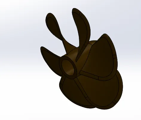
Features used to create propeller:
- Revolve boss
- Loft boss
- Fillet
- Circular pattern
- Extrude cut
Circular pattern:
Replicate selected parts, faces, or features about an axis or mate connector (inferred or existing). Create new parts or modify existing parts by adding or removing material, or intersecting parts in its path.
HULL:
The main body of a ship or other vessel, including the bottom, sides, and deck but not the masts, superstructure, rigging, engines, and other fittings.
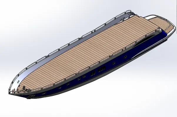
Features used to create hull:
- Sketch
- Projected curve
- Surface loft
- Surface trim
- Surface extrude
- Knit
- Surface fill
- Shell
- Extrude cut
- Fillet
- Mirror
- Appearances
PROJECT CURVE:
You can project a sketched curve onto a model face to create a 3D curve. You can also create a 3D curve that represents the intersection of two extruded surfaces generated by creating sketches on two intersecting planes.
SURFACE LOFT:
Loft Surfaces are surfaces generated by multiple 3D Curves or existing edges creating a smooth tangency between the selected curves. Match Points are created between each selection denoting the orientation and path of the loft surface.
SURFACE TRIM:
You can cut a solid model by removing material with a surface or plane. With multibody parts, you can select which bodies to keep.
SURFACE EXTRUDE:
- Extruding Surfaces from a 2D or 3D Face
You can create extruded surfaces from models that include 2D or 3D faces and knit the extruded surfaces to surrounding features.
- Capping an Extruded Surface at One End
You can cap an extruded surface at one end or at both ends.
KNIT:
The Knit Surface tool is used to combine two or more faces and surfaces into one.
FILL SURFACE:
The Filled Surface feature constructs a surface patch with any number of sides, within a boundary defined by existing model edges, sketches, or curves, including composite curves.
SHELL:
The shell tool hollows out a part, leaves open the faces you select, and creates thin-walled features on the remaining faces. If you do not select any face on the model, you can shell a solid part, creating a closed, hollow model. You can also shell a model using multiple thicknesses.
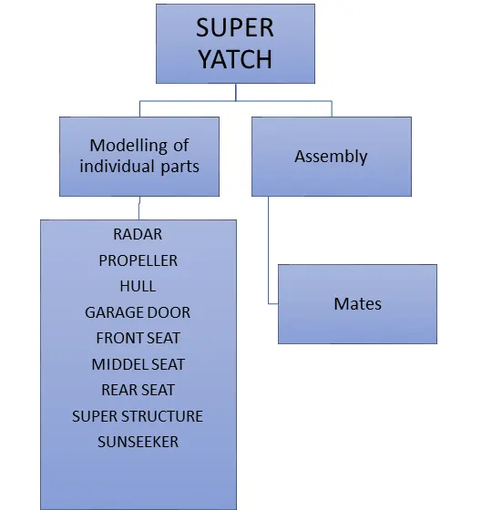
GARAGE DOOR:
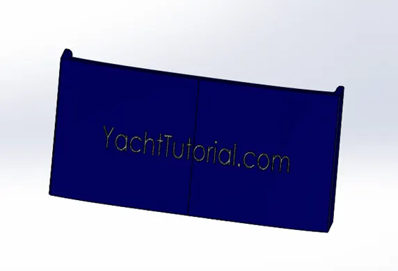
Features used to model rear fender:
- Sketch
- Extrude
- Shell
- Fillet
- Mirror
- Appearances
FRONT SEAT:
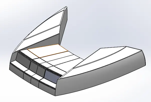
Features used create front seat:
- Sketch
- Surface extrude
- Fillet
- Surface loft
- Surface trim
- Knit
- Revolve
- Surface sweep
- Dome
DOME:
The software calculates the distance using the radius of the arc as a basis for the dome. It creates a dome that is tangent to the adjacent cylindrical or conical face.
REAR SEAT:
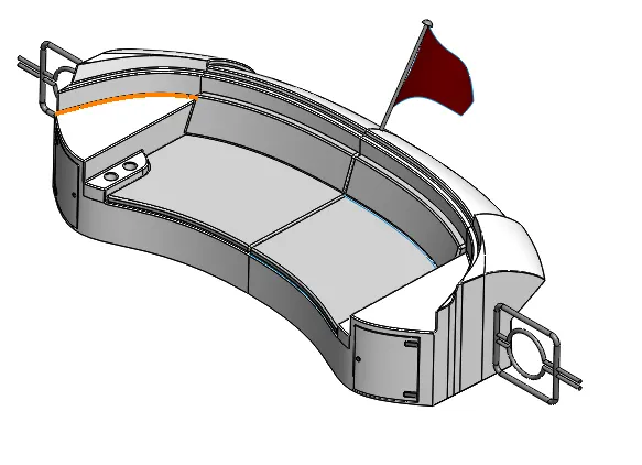
Features used create REAR seat:
- Sketch
- Surface sweep
- Surface trim
- Surface extrude
- Knit
- Surface loft
- Fillet
- Mirror
- Surface offset
- Ruled surface
- Extrude cut
- Extrude boss
- Appearances
RULED SURFACE:
The Ruled Surface command creates surfaces that extend out in a specified direction from selected edges. Examples of how you can use ruled surfaces: Add tangent extensions to complex surfaces. Create drafted sidewalls. Replace non-drafted surfaces on imported models with drafted surfaces
MIDDEL SEAT:
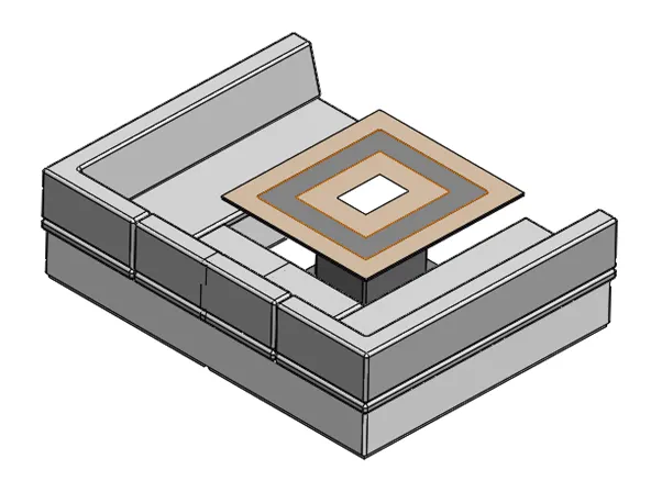
Features used to create middle seat:
- Extrude
- Fillet
- Mirror
- Extrude cut
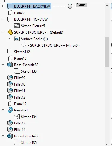
SUPER STRUCTURE:
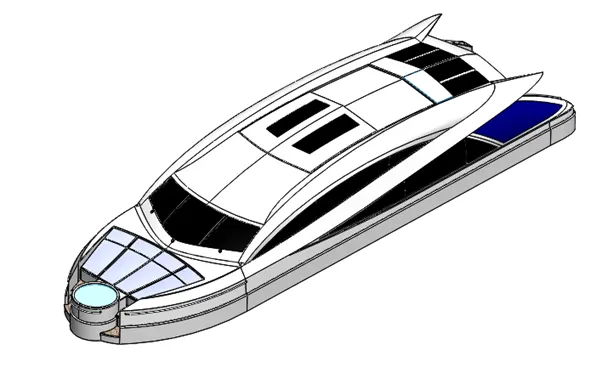
Features used:
- Sketch
- Surface extrude
- Surface sweep
- Knit
- Fillet
- Surface loft
- Surface trim
- Ruled surface
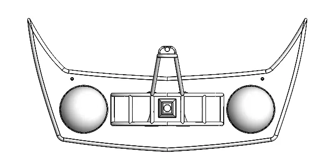
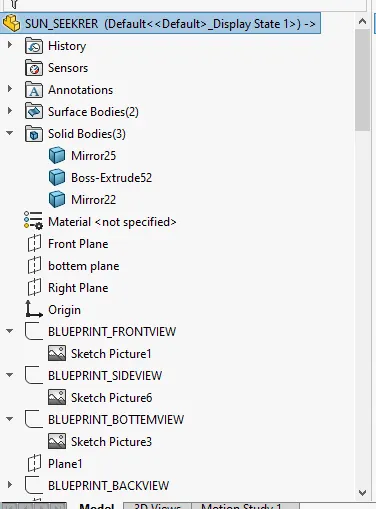
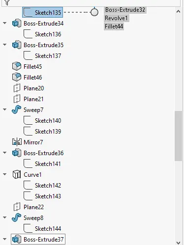
SUN SEEKER:
Features used:
- Extrude boss
- Fillet
- Surface sweep
- Dome
- Revolve
- Mirror
- Shell
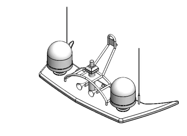
ASSEMBLY:
Mates
- Concentric
- Coincident
- Distance
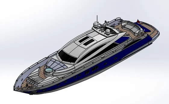
Isometric view
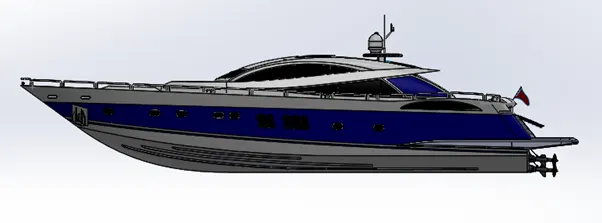
Side view
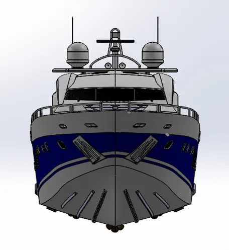
Front view
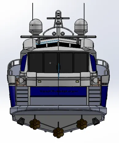
Back view
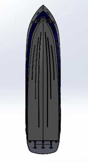
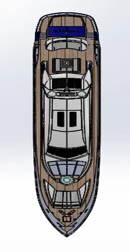
Bottem view and top view
CONCLUSION:
- Modelling the parts of the sunseeker yatch.
- Inserted the parts with required mates.
- Created a well-defined assembly.