Advanced Sheet Metal Design Using NX Cad Challenge_2_Box Assembly
Box Assembly
Objective
Designing a box assembly using NX sheet metal application using basic features.
Introduction
NX Sheet Metal provides a set of tools within the NX design environment that allows for simple and fast design of sheet metal parts, dependent on their material and manufacturing process, the most common of which is straight brake sheet metal forming.
Box assembly design is done using sheet metal application in NX11 application. Using Features such as tab, normal cutout ,bend , flange , break corner ,unbend , hole , dimple , bead , mirror features, rebend , flat pattern.
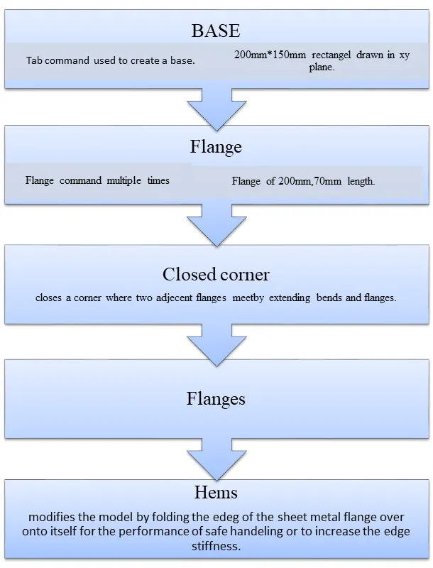
Design process
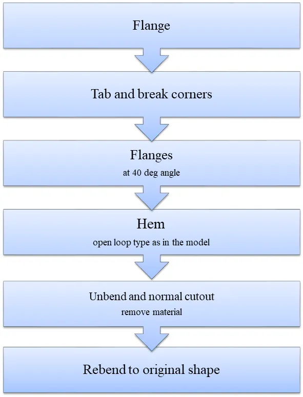
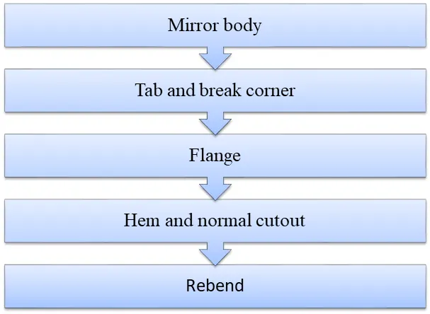
Description
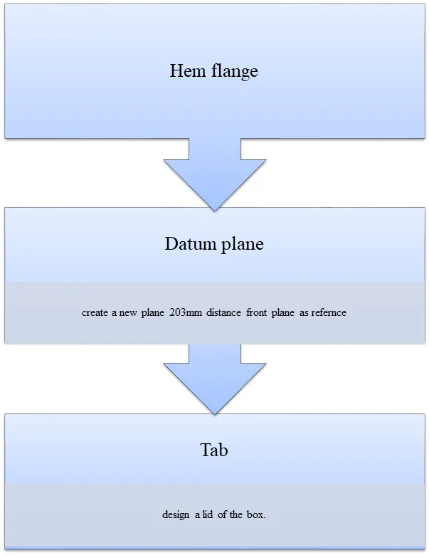
- Tab – Creates a base feature by extruding the sketch along a vector by thickness value or adds material to a plane face.
- Normal cutout – Cuts the model perpendicular to the sketch.
- Closed corner - closes a corner where two adjacent flanges meet by extending bends and flanges.
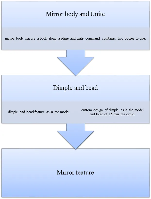
- Mirror body - mirror body mirrors a body along a plane.
- Unite - unite command combines two bodies to one.
- Datum plane – creating a new plane.
- Bend – Modifies the model by bending the material at one side of a sketch line adding a bend between sides.
- Flange – Adds a flange to a planar face adds a bend between the two.
- Break corners – Rounds a sharp corner.
- Unbend – Flattens a bend.
- Hole – Cuts a hole into a part.
- Dimple – Lifts a area inside a model which simulates stamping a tool.
- Bead – Lifts a material along a counter of a sketch that simulates stamping a tool.
- Mirror feature – Mirrors a feature/features along a plane.
- Rebend – Rebending to the required original shape.
- Flat pattern – Creates a flat pattern feature from a formed sheet metal.
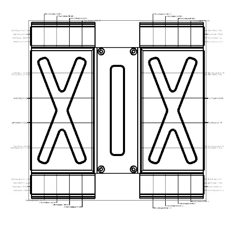
DWG Sheet
Images
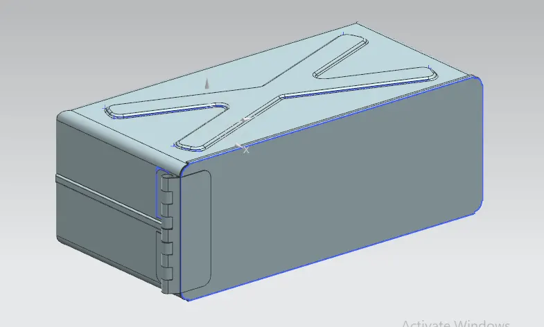
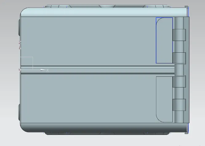
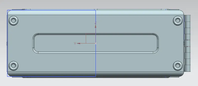
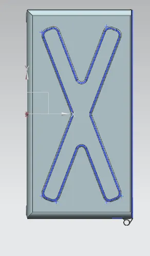
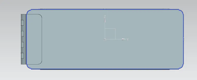
Conclusion
The model of the box assembly is obtained by using basic features of NX11 sheet metal application.