Photo Realistic Rendering
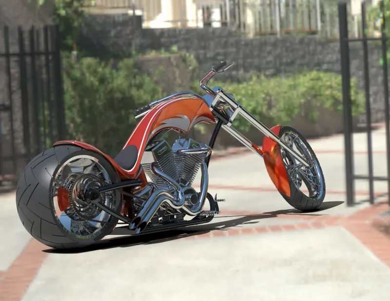
MODELLING AND RENDERING OF AN AMERICAN CHOPPER
OBJECTIVE :
- To create different parts of chopper in Solidworks with differnt types of sketches and features.
- To assemble all the modelled parts to create a chopper.
- To create photorealistic rendered images of the chopper using Solidworks Visualize.
INTRODUCTION :
The chopper is made by assembling all part modellings. It consists of following parts
- Chain.
- Transmission Belt.
- Kick-stand.
- Pedal.
- Front fender.
- Rear fender.
- Oiltank.
- Front wheel.
- Rear wheel.
- Engine.
- Fuel tank.
- Front fork.
- Chassis.
DESIGN METHODOLOGY :
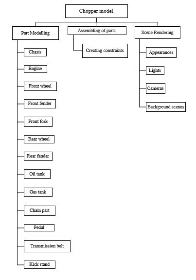
TO0LS AND FEATURES :
Chamfer : The chamfer tool creates a beveled feature on selected edges, faces, or a vertex.
Combine : The Combine feature allows you to add two bodies together, and keep the area that is common to them.
Dome : This feature is used to provide dome shape to the surfaces.
Extrude : This tool is used to create 3D models by using 2D sketches.
Fillet : Fillet creates a rounded internal or external face on the part. You can fillet all edges of a face, selected sets of faces, selected edges, or edge loops.
Loft : The loft tool help you create smooth and organic shapes. It creates a shape by making transitions between multiple profiles and guides curves thus allowing you to create complex geometry with a single tool.
Mirror : This feature creates a copy of a feature, mirrored about a face or a plane. You can select the feature or you can select the faces that comprise the feature.
Pattern : The Curve Driven Pattern tool allows you to create patterns along a planar or 3D curve. To define the pattern, you can use any sketch segment, or the edge of a face (solid or surface), that lies along the plane. You can base your pattern on an open curve, or on a closed curve, such as a circle.
Projected curve : The Projected Curve tool project curves from 2D and 3D sketches, onto faces and planes. You can replace one or more of the sketches that make up a projected curve of two sketches projected onto one another.
Revolve : Revolve adds or remove material by revolving one or more profiles around a centerline. You can create revolved boss/bases, revolved cuts, or revolved surfaces. The revolve feature can be a solid, a thin feature, or a surface.
Shell : The shell tool hollows out a part, leaves open the faces you select, and creates thin-walled features on the remaining faces. If you do not select any face on the model, you can shell a solid part, creating a closed, hollow model. You can also shell a model using multiple thicknesses.
Surface split : This tool is used to split two surfaces of a solid body.
Surface knit : The Knit Surface tool is used to combine two or more faces and surfaces into one. Create a solid body when the knit surfaces form a closed volume.
Surface loft : Loft Surfaces are surfaces generated by multiple 3D Curves or existing edges creating a smooth tangency between the selected curves. Match Points are created between each selection denoting the orientation and path of the loft surface.
Surface sweep : Sweep Surfaces are surfaces that are generated from a section curve positioned along a path. Sweep by Two Guide Curves is defined as moving and adjusting a section curve along two guide curves.
Sweep : The Sweep tool is used to create solid/surface feature by sweeping closed loop sketch along the selected trajectory. This tool is generally used when we need to create tubes/bars following a curvature.
DESCRIPTION :
1. Chain :
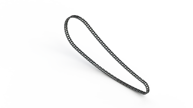
Chain is used to transmit power from engine to rear wheel through sprockets. The features used are,
- Extrude
- Pattern
- Mirror
- Fillet
2. Transmission Belt :
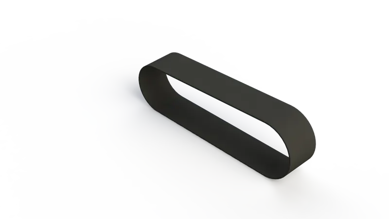
Transmission belt transmitts power. The features used are,
- Extrude
- Fillet
3. Kick-stand :
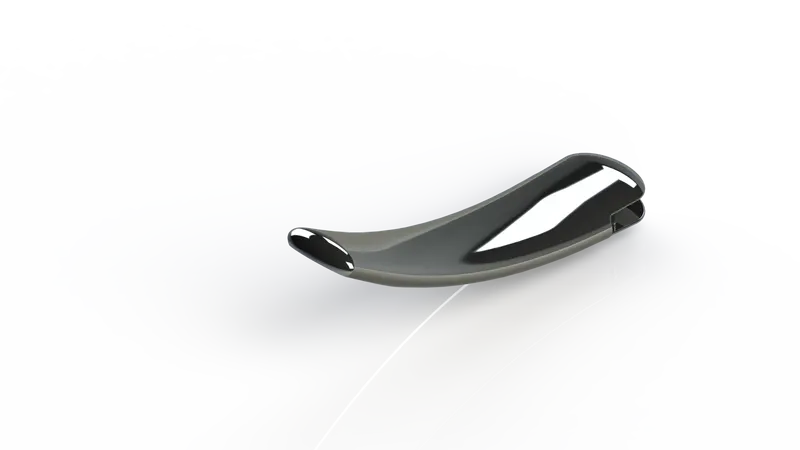
Kickstand allows the bike to stand upright without any external support. The features used are,
- Loft
- Dome
- Extrude
- Split
- Fillet
4. Pedal :
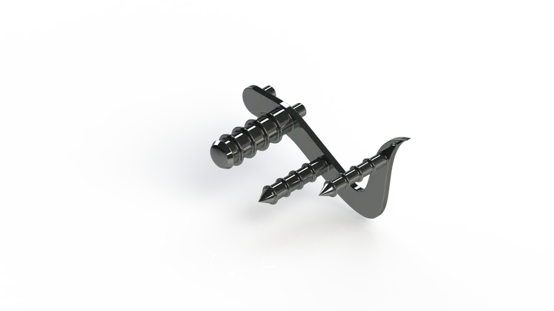
Pedals are used to operate brakes or switch gears of the chopper. The features used are,
- Extrude
- Fillet
- Dome
- Chamfer
- Pattern
5. Front fender :

The purpose of the fender is to prevent mud, dust and rocks from being thrown towards the rider and bike components. The features used are,
- Revolve
- Split
- Fillet
6. Rear fender :
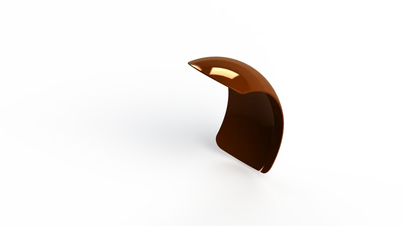
The purpose of the fender is to prevent mud, dust and rocks from being thrown towards the rider and bike components. The features used are,
- Revolve
- Split
- Fillet
- Shell
7. Oiltank :
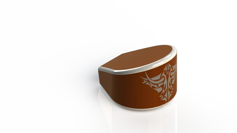
It simply holds the oil. The features used are,
- Extrude
- Combine
- Fillet
- Shell
8. Front wheel :
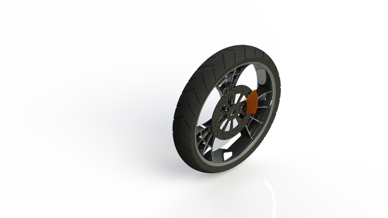
Front wheel revolves on an axel and helps to move over the ground. The features used are,
- Revolve
- Extrude
- Fillet
- Pattern
- Chamfer
9. Rear wheel :
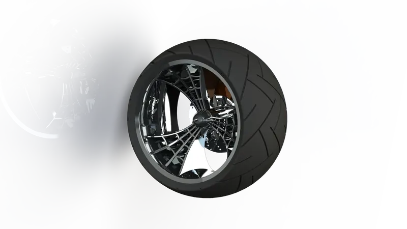
The rear wheel is the powered wheel in the bike. It propels the bike. The features used are,
- Revolve
- Extrude
- Pattern
- Combine
- Fillet
- Chamfer
10. Engine :
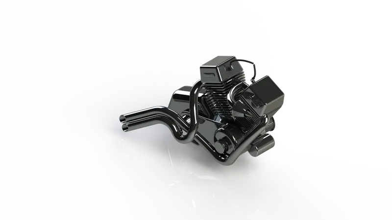
Engine is The power source of the vehicle. It generates power combustion of fuel. The features used are,
- Extrude
- Revolve
- Dome
- Fillet
- Chamfer
- Pattern
- Mirror
- Split
- Combine
- Sweep
11. Fuel tank :
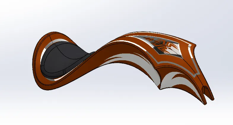
The Fuel tank stores the fuel and supply fuel to the Engine to generate power. The features used are,
- Surface sweep
- Surface Knit
- Projected curve
- Surface loft
- Split line
- Mirror
- Surface Knit
- Fillet
- Shell
12. Front fork :
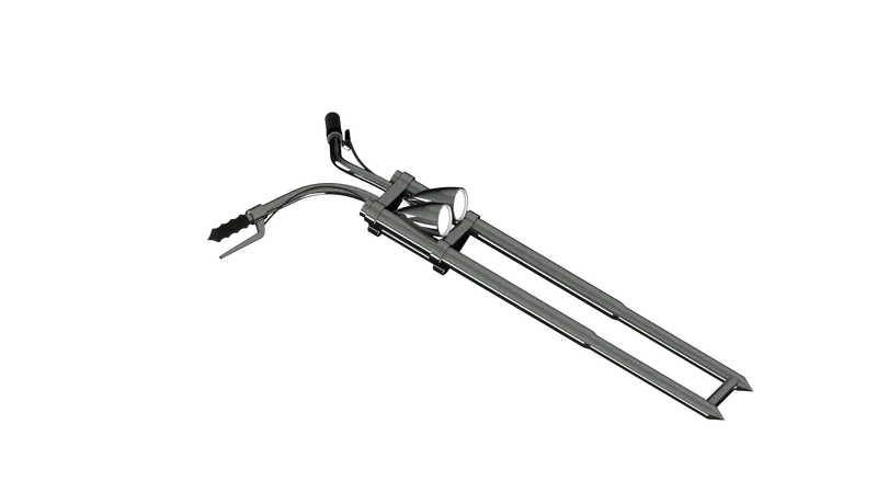
The front fork connects wheel and axle to the bike chassis. The features used are,
- Revolve
- Extrude
- Pattern
- Dome
- Fillet
- Sweep
- Projected curve
- Combine
13. Chassis :
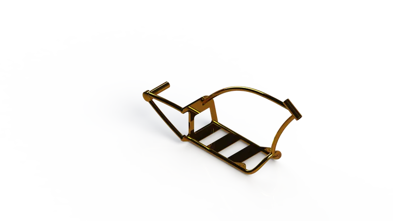
Chassis is the supporting frame of a vehicle on which various components of the vehicle are mounted. The features used are,
- Extrude
- Mirror
- Fillet
- Chamfer
- Dome
- Sweep
- Split
- Combine
- Revolve
ASSEMBLED IMAGES :
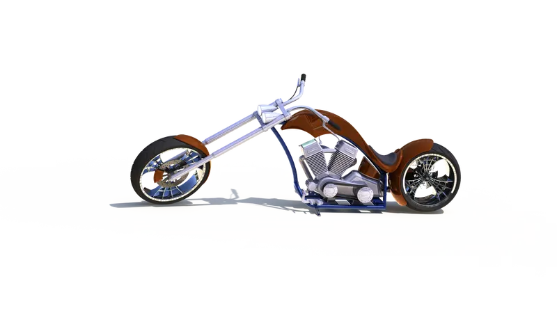
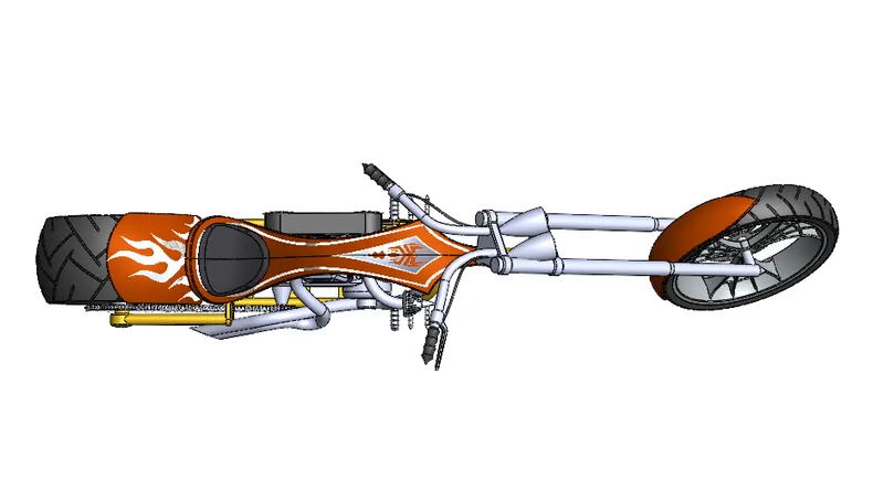
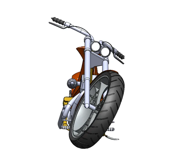
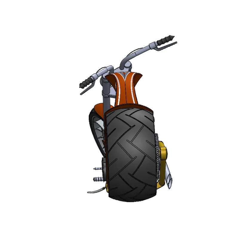
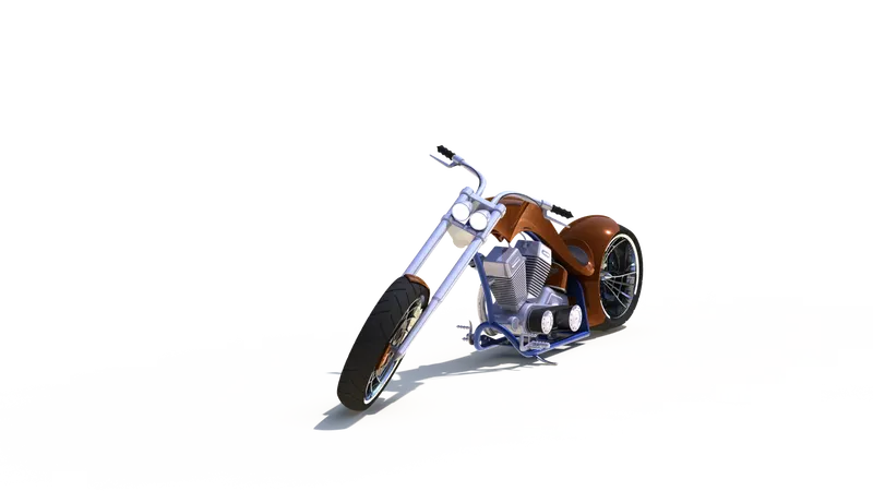
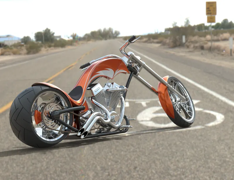
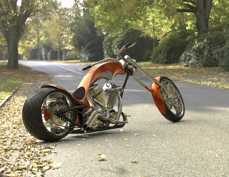
PHOTOREALISTIC RENDERED IMAGES :
CONCLUSION :
All the parts of the American Chopper were modelled and the assembly was created using Solidworks and the photorealistic renders of the chopper are created using Solidworks Vizualize.