Photo Realistic Rendering
Designing of American Chopper using Solidworks
1. Objective:-
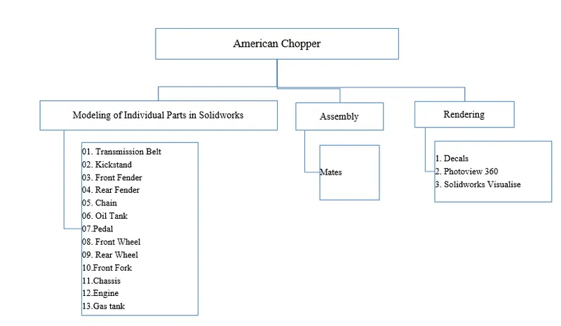
- The main objective is to create a model of American Chopper using a different module like Sketch, Feature, Surface, Evaluate, etc.
- How to assemble different parts with the help of mates.
- Know about the use of Decals, Lights, Cameras, etc.
- How to crate render of a real model using Photo 360 and Solidworks Visualize.
2. Introduction:-
Solidworks is one of the modeling software. This software is used to design 3-D models, 2-D drawings, Assembly, Renders, etc. In this project, we learned about many commands while designing American Chopper. American Chopper is a customized motorcycle.
3. Design Methodology/Approach:-
4. Description:-
4.1 To Create Different Components of American Chopper
In this module, we designed different components of American Chopper as per the given dimensions then saved (.prt) file.
4.1.01. Transmission Belt
The transmission belt transfers power from the engine to the gearbox.
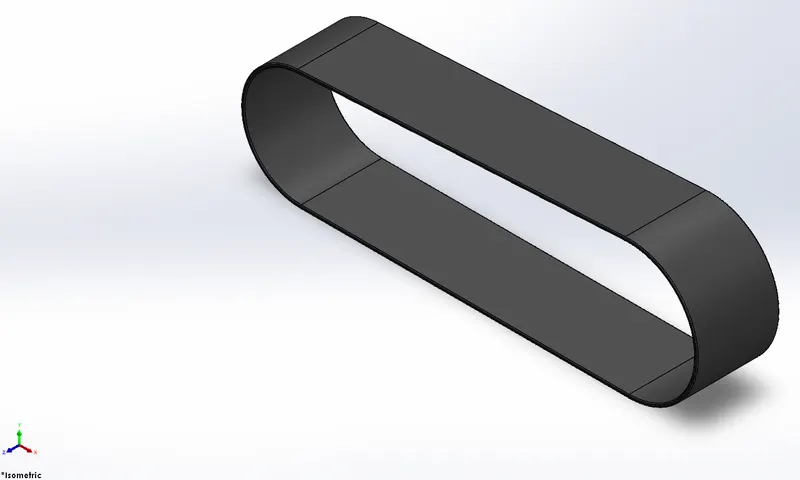
Features used to create Transmission Belt
- Sketch
- Offset
- Extrude Boss
- Fillet
Sketch:- Sketch is a 2-D view of a component. The sketch is drawn with the help of entities like line, circle, square, rectangle, arc, etc.
Offset:- This is used to draw a similar image with a fixed distance either inside or outside of the shape.
Extrude Boss:- Extrude feature is used to create a 3-D model from a 2-D sketch.
Fillet:- Fillet is used to convert sharp edges to round.
The procedure used to create Transmission Belt
- Create a new Solidworks Part file.
- Draw sketch on Front plane.
- Make the sketch fully defined.
- Exit from the sketch then creates solid using extrude command.
- apply fillet to remove sharp edges.
4.1.02. Kickstand
A kickstand is to support the motorcycle while in rest on the ground.
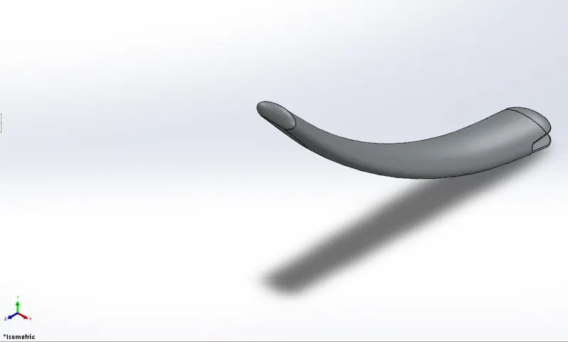
Features used to create Kickstand
- Sketch
- Loft
- Dome
- Extrude Boss
- Extrude Cut
- Split
- Fillet
Loft:- Loft feature is used to complex 3-D models between non-similar cross-section shapes.
Dome:- Dome feature is used to creating a solid while pulling the centroid outward from the solid. In Dome, feature centroid comes outward while edges remain stick on that edge.
Extrude Cut:- This is used to remove material from the solid with help of a sketch.
Split:- This is used to divide into planar or curved surfaces.
The procedure used to create Kickstand
- Create a new Solidworks Part file.
- Sketch is created on the mid-plane.
- Loft command is used to create a 3-D component of different cross section.
- Dome command is used to create squeezed surface on both hands.
- Extrude cut is used to remove the material from one end.
- Extrude is used to create a pin.
- Fillet is used to remove the sharp edges.
4.1.03. Front Fender
Front Fender protects the bike from mud. It is also known as a mudguard.
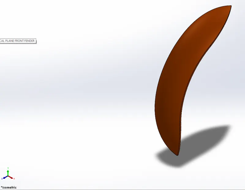
Features used to create Front Fender
- Sketch
- Offset Entities
- Trim Entities
- Revolve
- Dynamic Mirror
- Split
Trim Entities:- This is used to remove the extended line or curve at the intersection point.
Revolve:- This is used to create the circular 3-D components.
Dynamic Mirror:- It is used to mirror the pre-sketched entities.
The procedure used to create Front Fender
- Create a new Solidworks Part file.
- Sketch is created by curve.
- Revolve command is used to generate 3-D solid model.
- Trim is used to remove material in desired shape from both hands.
4.1.04. Rear Fender
Rear Fender protects the bike from mud. It is also known as a mudguard.
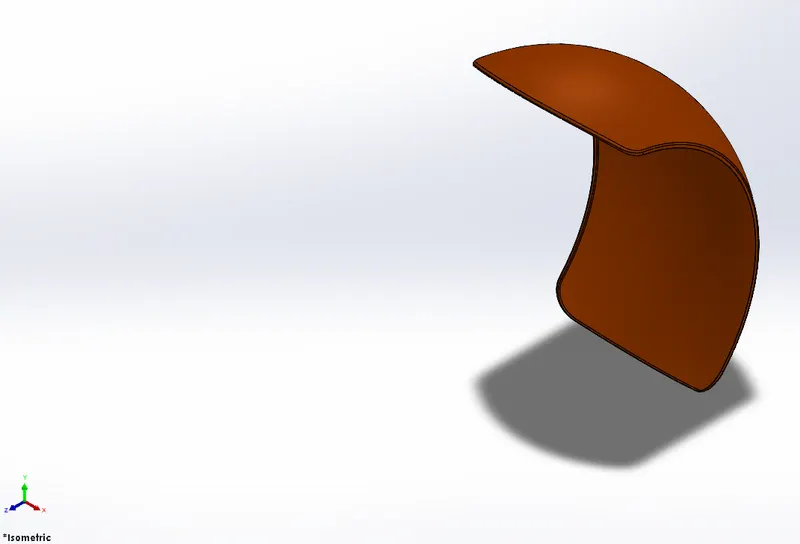
Features used to create Rear Fender
- Sketch
- Offset Entities
- Trim Entities
- Revolve
The procedure used to create Rear Fender
- Create a new Solidworks Part file.
- Sketch is created by curve.
- Revolve command is used to generate 3-D solid model.
- Trim is used to remove material in desired shape from both hands.
4.1.05. Chain
A chain is a transmission device that transfers power from the gearbox to the rear wheel.
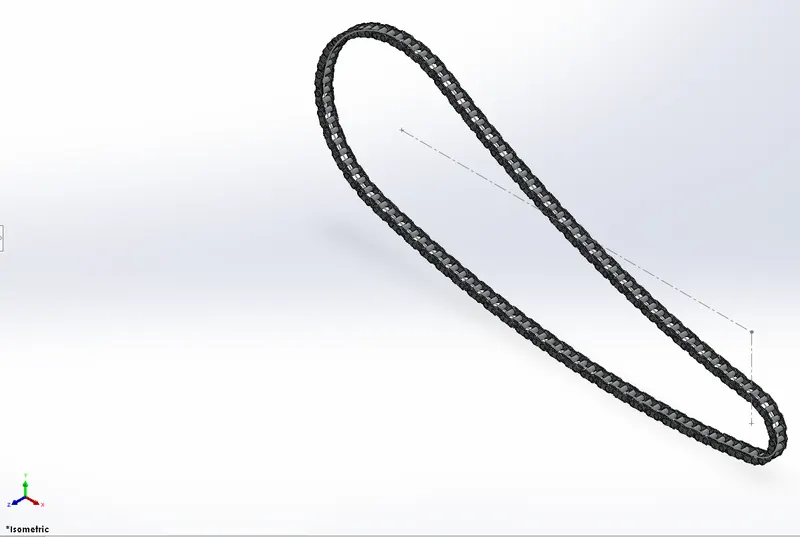
Features used to create Chain
- Sketch
- Trim Entities
- Fillet
- Blocks
- Extrude Boss
- Patterns
Blocks:- Block is used to save the repetitive element.
Patterns:- Pattern is used to create a similar object or feature in a different direction or in the desired direction.
The procedure used to create Chain
- Create a new Solidworks Part file.
- Links are designed using the sketches.
- Blocks are created of different links.
- Curve pattern is used to create similar component according to the curve.
- Mirror is used to create links on other side.
4.1.06. Oil Tank
Oil Tank is used to store the lubricant.
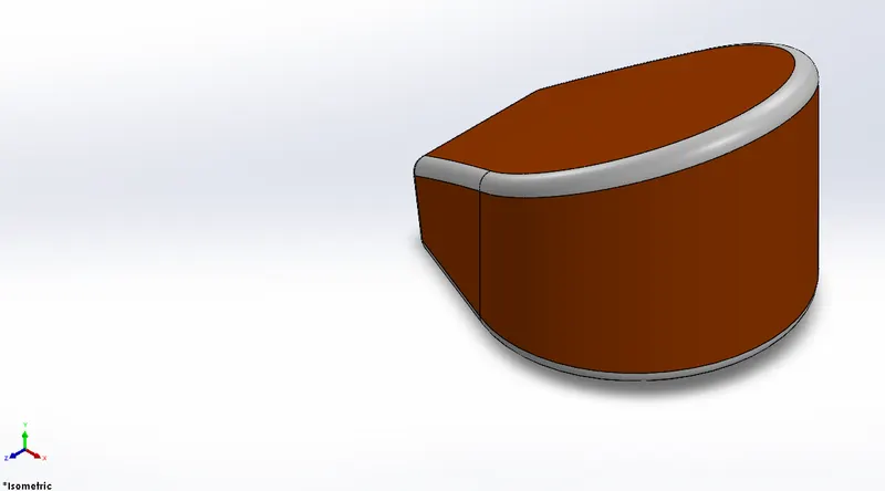
Features used to create Oil Tank
- Sketch
- Extrude Boss
- Combine
- Fillet
- Shell
Combine:- This feature is used to manually combine two bodies like add, subtract, etc.
Shell:- This feature is used to make any component hollow. We can remove any face if needed.
The procedure used to create Oil Tank
- Create a new Solidworks Part file.
- Sketch is created using input dimension and shape.
- 3-D model is created with the help of extrude command.
- Remove the sharp edge using fillet command.
- Shell command is used to make a component hollow.
4.1.07. Pedal
The pedal is used as a footrest, it helps the driver to change gear and use brake for the rear wheel.
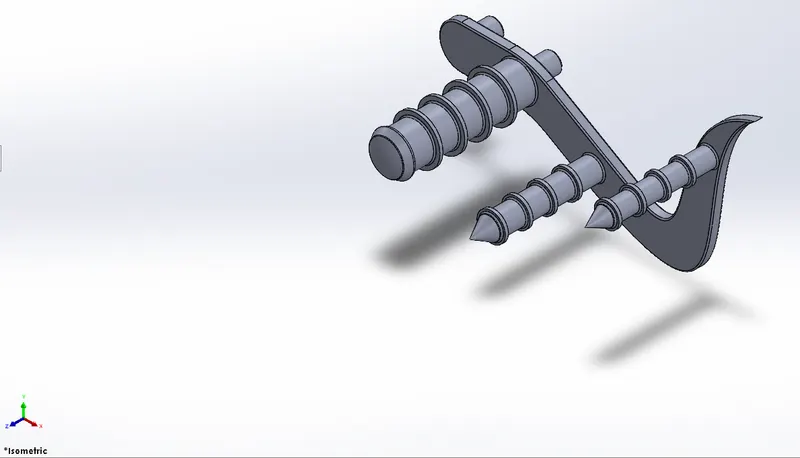
Features used to create Pedal
- Sketch
- Extrude Boss
- Fillet
- Linear Pattern
- Dome
- Chamfer
Linear Pattern:- It is used to create same feature in direction to a line.
Chamfer:- Champher is used to remove the sharp edge or corner. It converts a sharp edge or corner into tapered edge.
4.1.08. Front Wheel
Front Wheel consists of tyre, rim and disc brake.
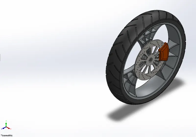
Features used to create Front Wheel
- Sketch
- Revolve
- Trim Entities
- Fillet
- Extrude Boss
- Revolve Cut
- Linear pattern
- Chamfer
- Extrude Cut
- Circular Pattern
Revolve Cut:- Revolve cut is used to remove the material in circular way.
4.1.09. Rear Wheel
Rear Wheel consists of a tyre, rim, sprocket and disc brake.
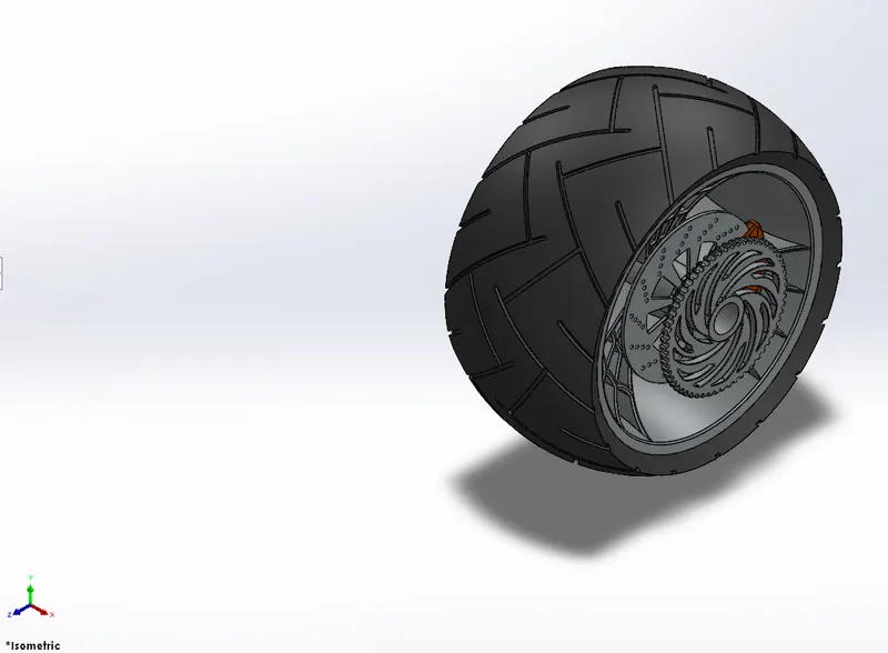
Features used to create Rear Wheel
- Sketch
- Revolve
- Trim Entities
- Fillet
- Extrude Boss
- Planes
- Revolve Cut
- Linear pattern
- Chamfer
- Extrude Cut
- Circular Pattern
Planes:- Planes are used at different positions to create any features.
4.1.10. Front Fork
Front Fork consists of the accelerator, headlights, shock absorbers, clutch and front brake control.
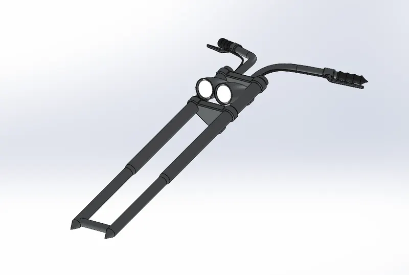
Features used to create Front Fork
- Sketch
- Extrude Boss
- Trim Entities
- Revolve
- Split
- Move / Copy Bodies
- Dome
- Mirror
- Combine
- Projected Curve
- Sweep
Move / Copy Bodies:- It is used to move any component or create a copy of any component.
Projected Curve:- It is used to create a 3-D curve from two 2-D curve or line.
Sweep:- It is used to create a 3-D profile or same cross section along any 2-D sketch.
4.1.11. Chassis
Chassis is made of different dimensions of pipe, rod, plate, etc. at different-different positions.
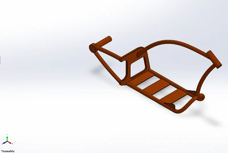
Features used to create Chassis
- Sketch
- Offset Entities
- Convert Entities
- Project Curve
- Trim Entities
- Sweep
- Split
- Revolve
- Extrude Cut
- Fillet
- Combine
Convert Entities:- It is used to copy a sketch from any 3-D shape or sketch.
4.1.12. Engine
The engine is the powerhouse of a vehicle. It is made of a combination of different materials. It takes fuel as an input and produces power for the vehicle to move.
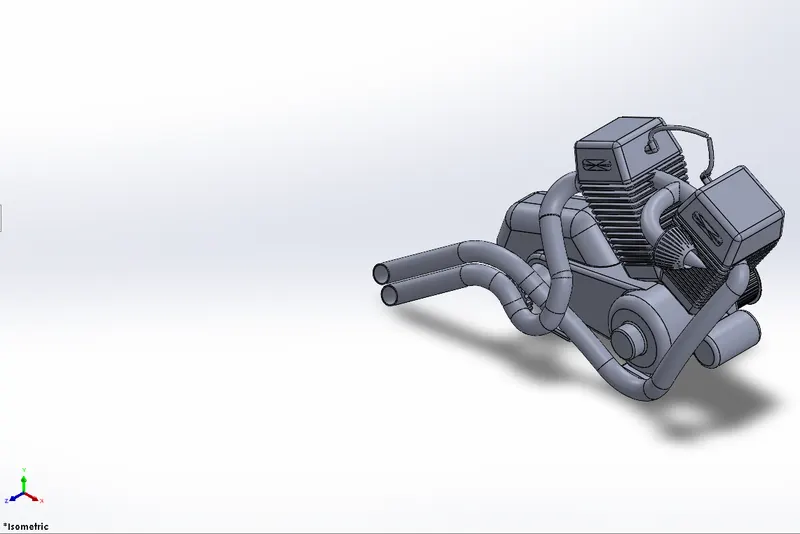
Features used to create Engine
- Sketch
- Trim Entities
- Revolve
- Extrude Boss
- Extrude Cut
- Offset Entities
- Dome
- Fillet
- Projected Curve
- Composite Curve
- Sweep
- Mirror
- Circular Pattern
- Split
Composite Curve:- It is used to create a 3-D curve from a 3-D curve or a line.
4.1.13. Gas tank
Gas Tank is used to store fuel. It is also known as the fuel tank.
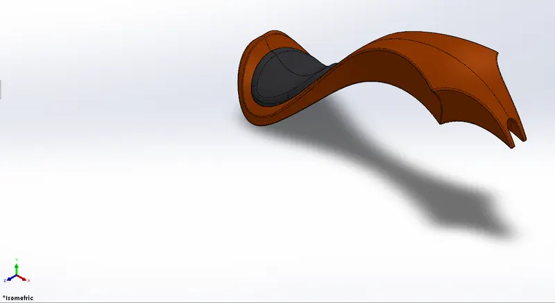
Features used to create Gas tank
- Sketch
- Trim Entities
- Projected Curve
- Sweep Surface
- Loft Surface
- Fill Surface
- Surface Trim
- Surface Knit
- Sweep Cut
- Fillet
Sweep Surface:- It is used to generate a surface along any path of same cross section.
Loft Surface:- It is generated with the help of 3-D curve or edge between two same or different cross section.
Fill Surface:- It is used to fill any surface by curves or lines at different positions.
Surface Trim:- It is used to remove any extended surface with reference of any plane or surface.
Surface Knit:- It is used to knit the surface and removing the gap between them.
Sweep Cut:- It is used to remove same cross sectional according to the path.
5. Assembly of American Chopper
- Create a new assembly file.
- Insert all parts in assembly.
- Fix the frame.
- Assemble all components using mates at desired location.
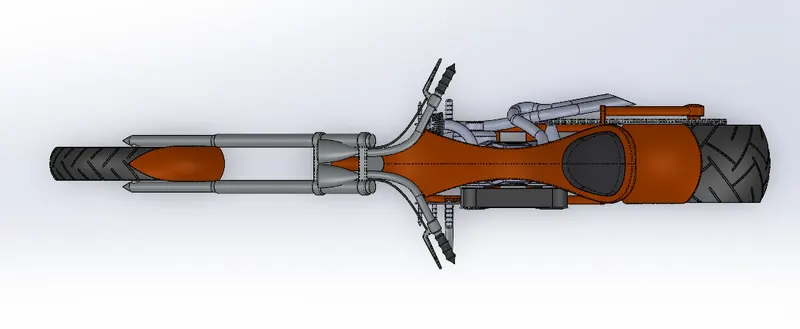
Top view of American Chopper
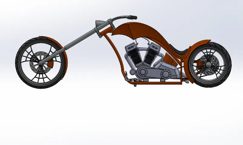
Left Side view of Assembly
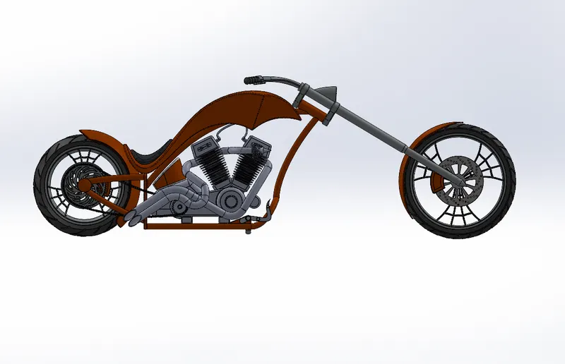
Right Side view of Assembly
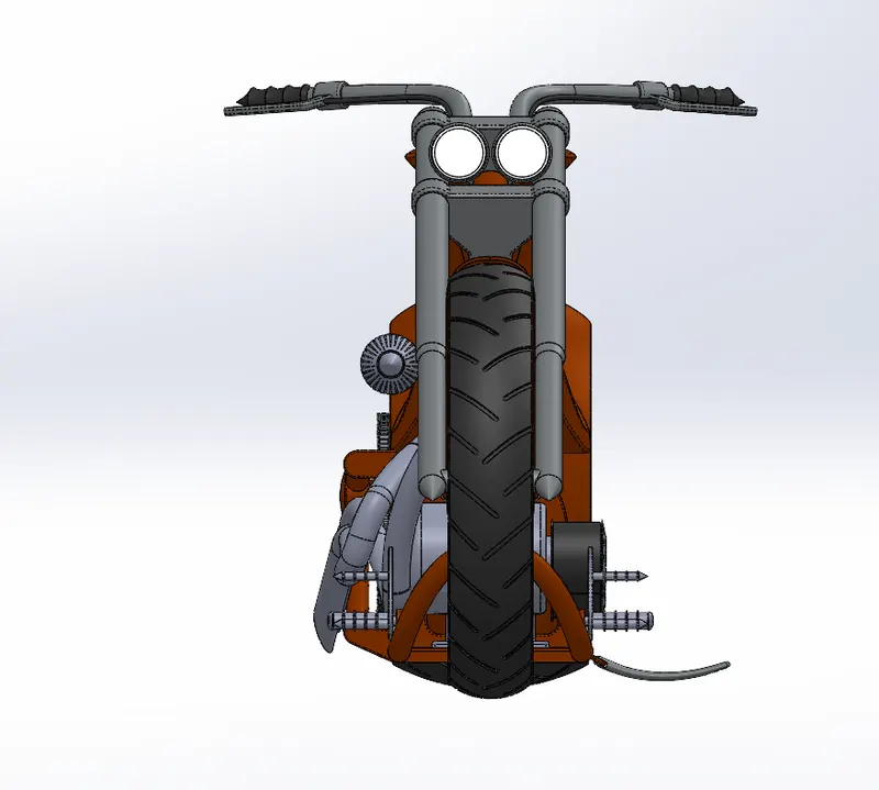
Front view of American Chopper
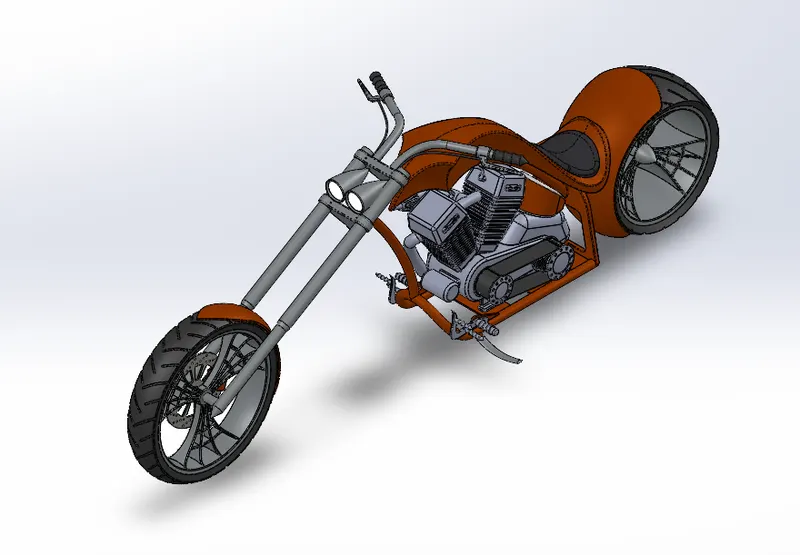
Isometric view of Assembly
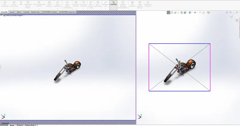
Camera 1 View of American Chopper
Mates:- It is used for joining method between two components. Mates are used decrease the degree of freedom of any component. Differnet types of mates used in the assembly are coincident, distance, concentric, limit angle, width, parallel, tangent,etc.
6. Render Images
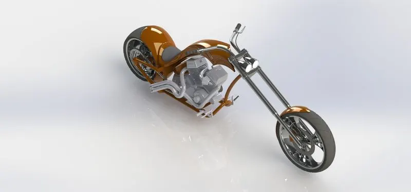
Render 1
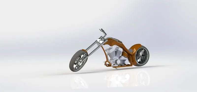
Render 2
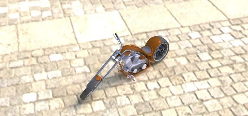
Render 3
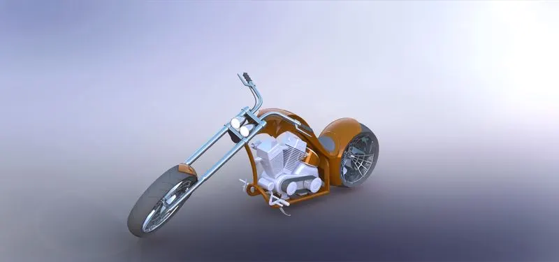
Render 4
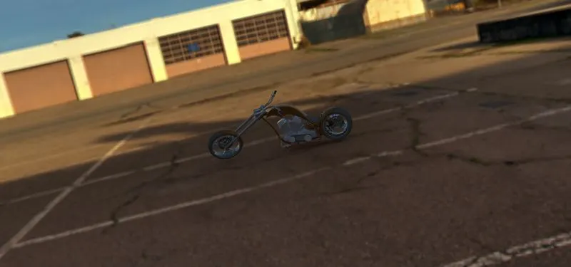
Render 5
7. Conclusion:
- Knowledge of create a 3-D model from blueprint.
- Knowledge of different modules like Sketch, Features, Surface, Evaluate, photo 360, Solidworks Visualize, etc. can be obtained while creating 3-D model.
- knowledge of Render tools, Camera setup,add Decals, appearances, etc. can be obtained.