Photo Realistic Rendering
DESIGN AND ASSEMBLY OF AMERICAN CHOPPER BIKE
Objective:
To understand the Solidworks software’s user interface and thereby modelling the different parts of the chopper bike. Then assembling the parts and rendering the same in Solidworks Visualize in a real life-like environment.
Introduction:
The SOLIDWORKS®CAD software is a mechanical design automation application that lets designers quickly sketch out ideas, experiment with features and dimensions, and produce models and detailed drawings. In this article, we discussed the detailed methodologies used to model the American Chopper bike.
The American chopper bike is made up of the following parts:
- Transmission Belt
- Kick Stand
- Front fender
- Rear fender
- Oil tank
- Stand
- Chain
- Front wheel
- Rear wheel
- Front fork
- Chassis
- Engine
- Gas tank
- Transmission belt:
A transmission belt is used to transmit power from the engine to the gear box.The features used to model the transmission belt is:
- Sketch: The sketch is a two-dimensional representation of the model to be created.
- Extrude: Converting the 2D sketch/profile to a 3D profile is known as Extrude Boss/base.
- Fillet: The feature used to round the sharp edges in a 3D profile/sketch.
- Offset: Adds sketch entities by offsetting faces, edges, curves, or sketch entities a specified distance.
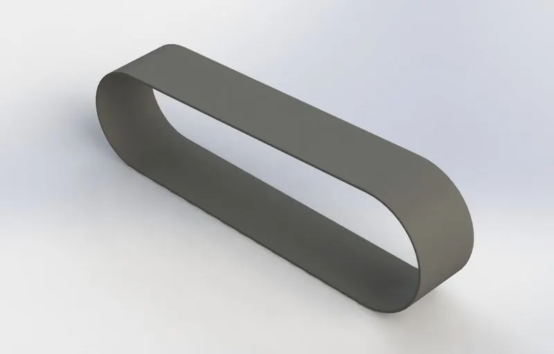
The following are the procedure to model the transmission belt:
- Firstly, open Solidworks software, then click on the new part file.
- Select the front plane and draw the transmission belt 2d view as shown above using arc and line.
- Make sure the line intersecting the arc to be tangent in relation and thereby fully defining the sketch. Then the sketch is Offsetted and exit the sketch.
- Then select the sketch and extrude to 88mm. by selecting the appropriate contours.
- Then apply a 1mm fillet to the edges.
- Lastly, apply appearance as matte rubber.
- Kickstand
It gives the support to stand the bike on the land. The features used to model the Kickstand are:
- Loft: Adds material between two or more sketches to make a solid feature.
- Dome: Adds one or more dome-like shapes on the planar or non-planar surfaces.
- Cut-extrude: This feature is used to remove material from the 3D model using the sketched profile.
- Split: Use the Split feature to create multiple parts from an existing part. You can create separate part files, and form an assembly from the new parts. You can split one or more solid or surface bodies. To split a surface, the Trimming Surface must extend past the boundaries of the surface to split.
- Other features like Extruded Bose/base, Sketch, and fillets.
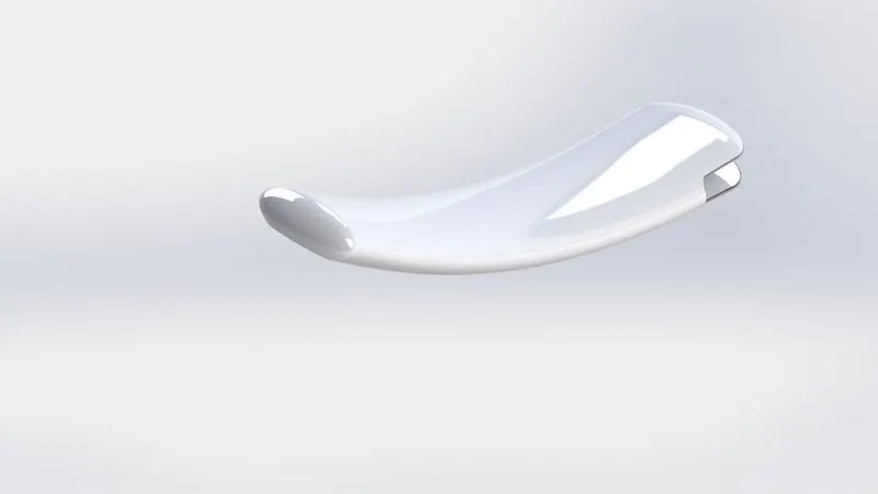
The following are the procedure to model the Kickstand:
- Select the front plane to draw the ellipse, which is the two ends/profile for the lofted boss.
- Select the midplane to draw the spline, which is used as a guide curve for the lofted boss.
- Exit the sketch and select two ellipse sketches as profiles and spline as guide curve.
- Then apply the dome feature at the two flat ends to give the nice look.
- Cut extrude the bigger dome end to fix with the chassis.
- Then use the split feature to flatten the surface in the lower ends, which comfortably touches the ground.
- Then fillet the sharp edges on the cut extruded surface.
- Finally, chrome plate appearance is applied to the kickstand.
3. Front fender
The fender's primary purpose is to prevent sand, mud, rocks, and rainwater being thrown into the air by rotating tire. The features used to model the front fender are:
- Revolved Boss/Base: Revolves add or remove material by revolving one or more profiles around a centreline. You can create revolved boss/bases, revolved cuts, or revolved surfaces. The revolving feature can be a solid, a thin feature, or a surface.
- Trim entities: Trims open sketch entities outside of two bounding entities. Use the Trim Property Manager to select a trim type and control other trimming options.
- Offset entities: Offset entities take a copy of your existing geometry and copy it at an offset. Instead of recreating geometry, you can use this to quickly sketch based on model geometry.
- Other features like the sketch, split, and fillet.
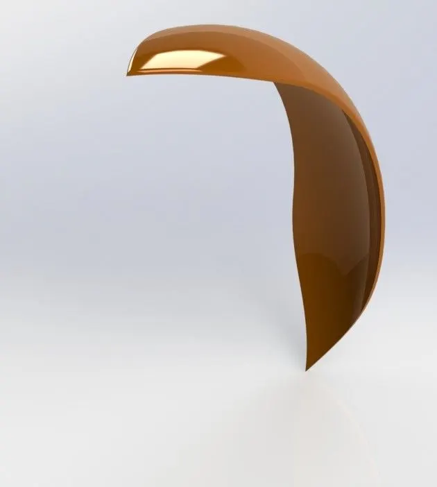
The following are the procedure to model the front fender:
- The midplane is renamed as a vertical plane and selected for the sketch to draw a profile for the fender with the help of trim and offset entities.
- Then the sketch is revolved and both ends of the fender are shaped with the help of a split feature
- The sharp edges are rounded with the help of the fillet feature.
- Finally, the Painted car sienna appearance is applied to the fender.
4. Rear fender:
- Revolved Boss/Base: Revolves add or remove material by revolving one or more profiles around a centreline. You can create revolved boss/bases, revolved cuts, or revolved surfaces. The revolving feature can be a solid, a thin feature, or a surface.
- Trim entities: Trims open sketch entities outside of two bounding entities. Use the Trim Property Manager to select a trim type and control other trimming options.
- Offset entities: Offset entities take a copy of your existing geometry and copy it at an offset. Instead of recreating geometry, you can use this to quickly sketch based on model geometry.
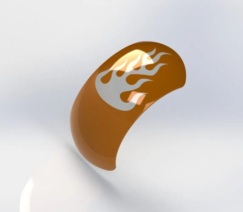
The same procedures are followed to model the rear fender as the front fender.
5. Pedal
The pedal is used to rest the foot of the rider which is attached to the chassis. The features used to model the pedal is:
- Linear pattern: Repeat the replica of features, faces, and bodies in one or two linear directions.
- Chamfer: It creates the bevelled feature on the selected edges, faces, or a vertex.
- Other features like the sketch, extrude boss/base, fillet, and dome.
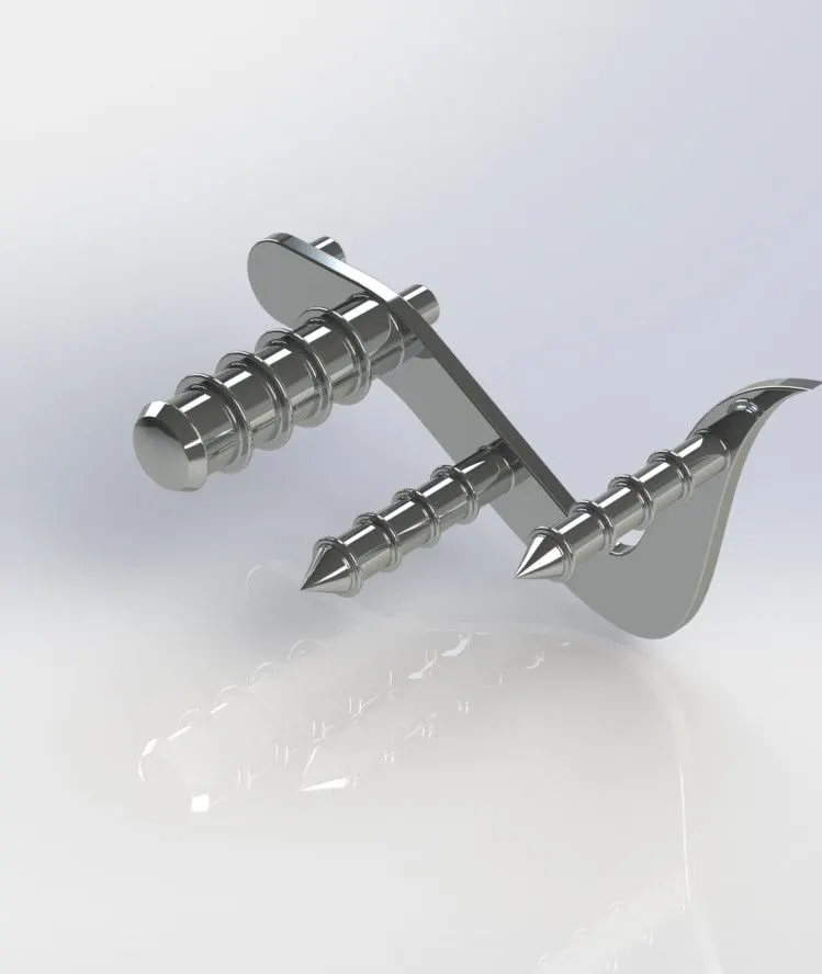
The following are the procedure to model the oil tank:
- Select the front plane to draw the sketch as shown in the above figure using line, spline, and circles.
- Then extrude the sketch except for the circles.
- These circles are extruded, which connects to the chassis.
- Select the top plane to draw the sketch and revolved to generate the footsteps of the pedal.
- Circles are drawn on the face of the pedal and extruded, later the feature is replicated linearly using a linear pattern tool, which serves as the grip of the footstep.
- The sharp edges to rounded using the fillet feature.
- Finally, chromium plate appearance is applied to the pedal.
6. Chain
The chain is to transmit power from the gearbox to the rear wheel. The features used to model the pedal is:
- Curve-driven pattern: As the name says, this tool allows you to create patterns along a planar or 3D curve.
- Blocks: In the case of making multiple sketches, we can use this tool. Using this tool, we can retrieve already made sketches.
- Other features like Extruded Boss/base, sketch, and fillets.
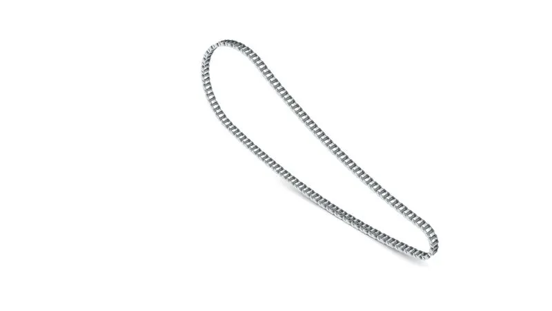
The following are the procedure to model the oil tank:
- The front plane is renamed as the midplane and draws the sketch for chain link and chain plate. These sketches are saved as blocks.
- The curve is drawn on the midplane for the chain.
- Using the block tool, sketches can be retrieved and extruded.
- Using the curve-driven pattern, chain links and plates are created along the curve.
- Sharp edges are rounded and chromium plate appearance is applied to the chain.
7. Front wheel
The features used to model the front wheel is:
- Circular pattern: This tool allows you to create patterns along a circular path.
- Revolved cut: Removes the material from the solid model by revolving a sketched profile around an axis.
- Other features like Extruded Boss/base, revolve, cut-extrude, chamfer, sketch, and fillets.
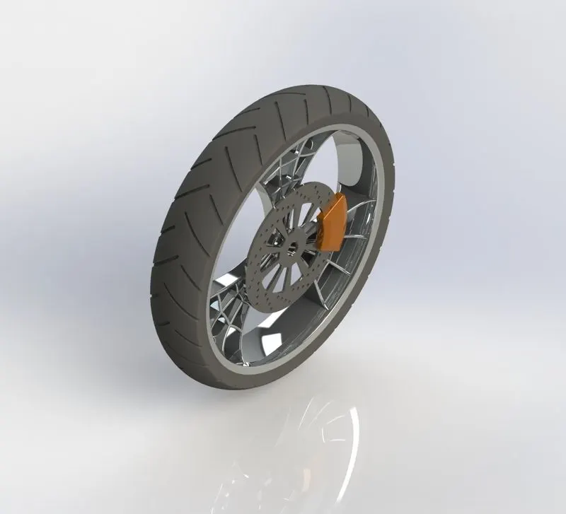
The following are the procedure to model the front wheel:
- The front plane is selected to draw the sketch for making the rim of the wheel and apply revolved boss/base.
- The right plane is selected to draw the sketch for the spider web spoke’s creation and extruded.
- The extra materials are cut using the “extruded” cut tool.
- Now the spoke is patterned along the circular path.
- The sketch is drawn on the front plane to make the rotor as shown in the image and extruded.
- Holes and cuts on the rotor are made using “extruded cut” and “circular pattern”.
- Then the rim and spider web spokes are combined to form a single body.
- Now the calliper is designed as shown in the image using the sketch, extrude and chamfer tools.
- To design the tyre, the rim’s profile is converted into entities and the profile of the tyre is drawn.
- Now the profile is revolved around the centre axis to make the tyre.
- The sketch is made on the surface of the tyre and cut to form the grip of the tyre. Finally desired appearance is applied to every part of the wheel.
8. Rear-wheel
The same features are used to model the rear wheel.
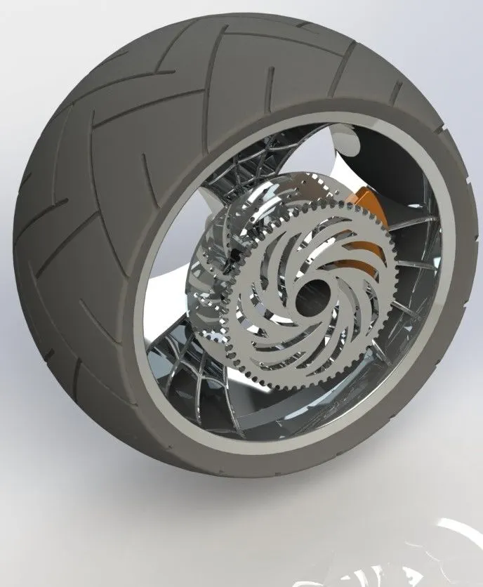
The following are the procedure to model the front wheel:
- The front plane is selected to draw the sketch for making the rim of the wheel and apply revolved boss/base.
- The right plane is selected to draw the sketch for the spider web spoke’s creation and extruded.
- The extra materials are cut using the “extruded” cut tool.
- Now the spoke is patterned along the circular path.
- The sketch is drawn on the front plane to make the rotor as shown in the image and extruded.
- Holes and cuts on the rotor are made using “extruded cut” and “circular pattern”.
- To design the sprocket, circles are drawn on the face of the rotor and extruded. The later chamfer is applied and the profile of the tooth is cut.
- The above feature is made on the entire part using a circular pattern tool.
- Then the rim and spider web spokes are combined to form a single body.
- Now the calliper is designed as shown in the image using the sketch, extrude and chamfer tools.
- To design the tyre, the rim’s profile is converted into entities and the profile of the tyre is drawn.
- Now the profile is revolved around the centre axis to make the tyre.
- The sketch is made on the surface of the tyre and cut to form the grip of the tyre. Finally desired appearance is applied to every part of the wheel.
9. Front fork
It is the part of the bike that holds the front wheel. It also houses the suspension of the bike as well.The features used model the front fork is:
- Swept Boss/Base: This is one of the useful features, which help to sweeps a closed profile through an open or closed path.
- Project curve: In this tool, you are going to use to form a 3D curve from two 2D curves from the two different planes.
- Plane: It is a reference plane to be created with reference to another plane, face, or vertex.
- Move/Copy body: As the name says, it is used to move/copy the body from one place to another.
- Other features like Extruded Boss/base, revolve, cut-extrude, dome, linear pattern, sketch, and fillets.
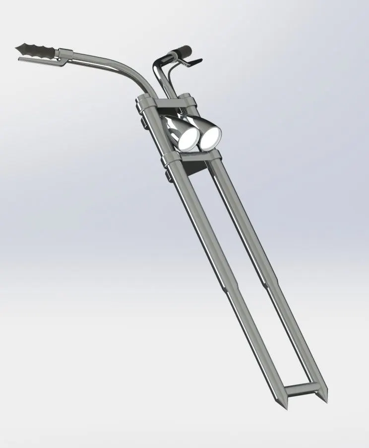
The following are the procedure to model the front wheel:
- Since this part is symmetric, we can model this on one plane and mirror it.
- In the front plane sketch for a shock absorber is made and revolve extrude it.
- Then half of the triple clamp is made using extrude, apply fillet to remove the sharp edges.
- In the same plane, draw the sketches and revolve extrude to create headlight.
- Using the projected curve tool guide curve for the handlebar is drawn and using the swept Boss handlebar is created.
- Then the entire body is mirrored about a reference plane created with reference to the front plane.
- Appropriate appearance is applied to every part of the front fork.
10. Chassis
It is the skeleton of the bike, as it attached to every component like engine, oil tank, gas tank etc. The features used to model the chassis is Sketch, Projected curve, Swept Boss/Base, Mirror entities, Extruded cut, Extruded Boss/Base, Split, Dome, Chamfer, Combine, and Fillet.
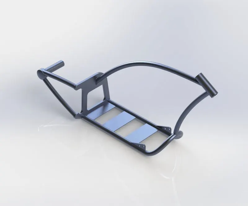
The following are the procedure to model the Chassis:
- The blueprint is imported to the part design, by adjusting location, transparency the sketch is drawn and extruded.
- Based on the blueprint, the sketch is drawn with the help of the projected curve, line and arc.
- Finally, all the parts are combined together and apply the desired appearance.
11. Engine
It is the powerhouse of the bike, which converts chemical energy to heat energy and from heat energy to useful mechanical work. The features used to model the engine is Sketch, Projected curve, Swept Boss/Base, Mirror entities, revolve, Extruded cut, Extruded Boss/Base, Split, Dome, Chamfer, Combine, and Fillet.
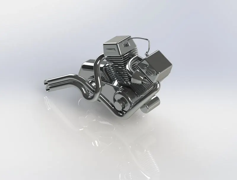
The following are the procedure to model the Chassis:
- The blueprint is imported to the part design, by adjusting location, transparency, the sketch is drawn in the front plane for making the base of the engine using three-point arc and lines and extruded to the specified dimension.
- Select the right plane to draw the profile of pulleys and revolved extrusion.
- Tooth on the pulleys is made then patterned around the pulleys.
- Then the V-shaped engine cylinder and sprocket is created.
- Using the sweep, revolve and circular pattern air filter and its connecting tube is created.
- Then using the projected curves and swept boss/base exhaust tubes are created.
- Finally, chromium plate appearance is applied to the engine.
12. Gas tank
It stores the fuel for the bike to drive. The features used to model the engine is:
- Extruded surface: Creates an extruded surface from a 2D sketch.
- Trim surface: Cuts a surface where one surface intersects with another surface, plane, or sketch.
- Lofted surface: Creates a lofted surface between the two or more profiles.
- Boundary surface: Creates surfaces that can be tangent or curvature continuous in both directions.
- Knit surface: Combines two or more adjacent and non-intersecting faces and surfaces into one.
- Split line: Projects a sketch to curved or planar faces, creating multiple separate faces.
- Swept surface: Creates a surface feature by sweeping open or closed profiles along an open or closed path.
- Other features like swept cut, shell, projected curve and fillet.
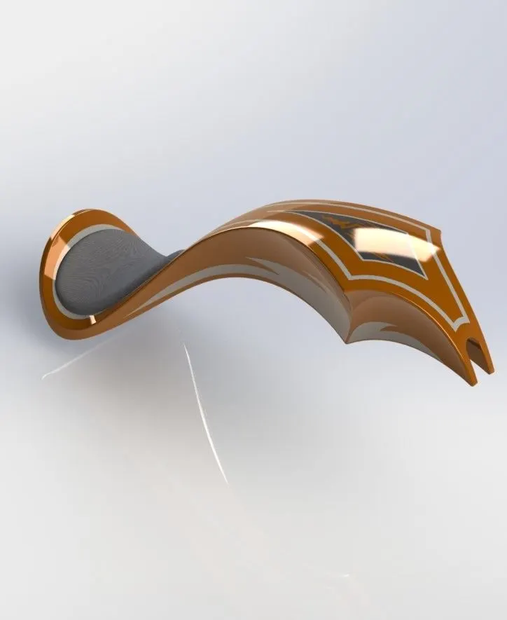
The following are the procedure to model the gas tank:
- The basic structure of the gas tank is created with reference to the imported blueprint with the help of Swept surface and trim surface tools.
- Using projected curves, lofted surface, and boundary surface sidewalls of the gas tank are created.
- Since the tank is symmetric about midplane it is mirrored about midplane.
- Then two surfaces are combined together by a knit surface.
- On the bottom, the plane sketch is drawn for the seat and project onto the gas tank using a split line tool.
- Later the sketch is extruded and combined together by a knit surface.
- Sharp edges to be rounded by giving fillets.
- Finally, the desired appearance is applied to the gas tank.
13. Oil Tank
It is used to store the engine oil, required to run the engine. The features used to model the oil tank is:
- Combine: This is one of the great features of Solidworks. There are three different ways we can use this tool i.e., Add, subtract, and common. The common function merges the two bodies and keeps the area common to them.
- Shell: This feature hollows out the inside of the solid, leaving behind a shell of a specified wall thickness.
- Other features like Extruded Boss/base, Sketch, and fillets.
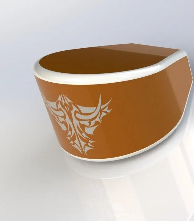
The following are the procedure to model the oil tank:
- Select the top plane to draw the oil tank body using arc and line with tangent relation and trim the unwanted lines.
- Then exit the sketch and extrude it.
- Select the midplane and draw the sketch and extrude it.
- Then combine the two bodies together using the combine feature.
- The sharp edges to rounded using the fillet feature.
- Using shell feature, make the solid body hollow with desired wall thickness
- Finally, apply the desired appearance to the oil tank.
Assembly of Chopper bike
The features used to assemble the different parts of the chopper as follows:
- Mates: Mates create geometric relationships between the components. It defines the allowable directions of linear and rotational movement of the components. The mates have several other options like
- Coincident mates: which makes two planar faces become coplanar.
- Concentric mates: This mate forces two cylindrical faces to become concentric.
- Parallel mate: This mate forces two planar faces to become parallel.
- Angle mates: Makes an angle between the selected entities.
- Limit angle mate: It is an advanced mate type that allows you to specify a range of angular values that a component is able to move.
- Width mate: It constrains a tab between two parallel planar faces or two non-linear planar faces.
- Tangent mate: Mate two entities tangent to the selected faces, edges, or vertices.
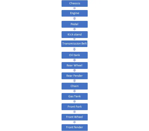
Assembly tree
The parts of the American chopper bike are assembled using the appropriate mates with the parts, parts are inserted in the Solidworks assembly as shown below:
Rendering:
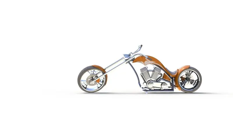
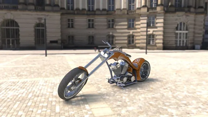
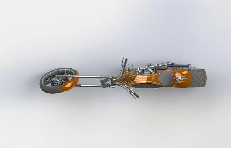
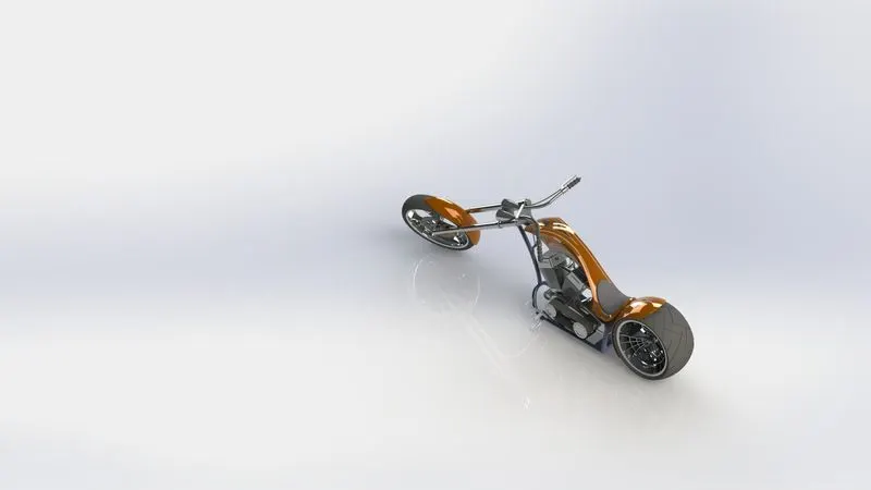
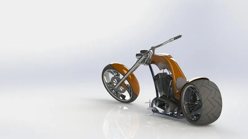
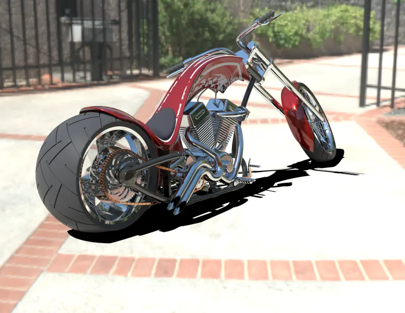
Before rendering, decals are added to the rear fender, Oil tank and gas tank. Cameras, background scenes and lights are set up.
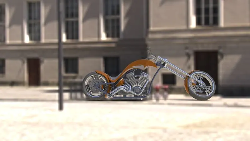
Rendering is the process of creating photo-realistic images in a real life-like environment. The render is done in PhotoView 360 of the Solidworks. The realistic render is created in Solidworks visualize.
Conclusion
In this project, we have understood and used several features of the Solidworks and thereby different parts of the chopper bike are modelled. After this, every part is assembled and decals are applied. Later by setting up lights and cameras photorealistic render is generated in PhotoView 360. On various background scenes, the American chopper bike is rendered using Solidworks Visualize to derive photo-realistic image in a real life-like environment.