Advanced Sheet Metal Design Using NX Cad Challenge_6_Bracket
DESIGNING OF BRACKET USING ADVANCED SHEET METAL
Objective:
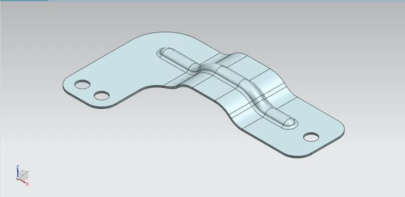
To design the bracket with the help of a 2D sketch using the advanced sheet metal in Siemens NX Sheet Metal application.
Introduction:
Sheet metal is a metal formed by an industrial process into thin and flat parts. It is one of the basic forms used in metalworking, and it can be cut and bent into a variety of forms. Countless everyday objects are made of sheet metal.
In this project, a bracket of sheet metal was designed to understand some of the operations done in the Siemens NX Sheet metal application. Brackets in general terms you can consider as a supporting system or a guiding system. In relatively long or vertical components brackets can be used to support. And in mechanisms and machines, brackets are guiding systems
Design Methodology/Approach:
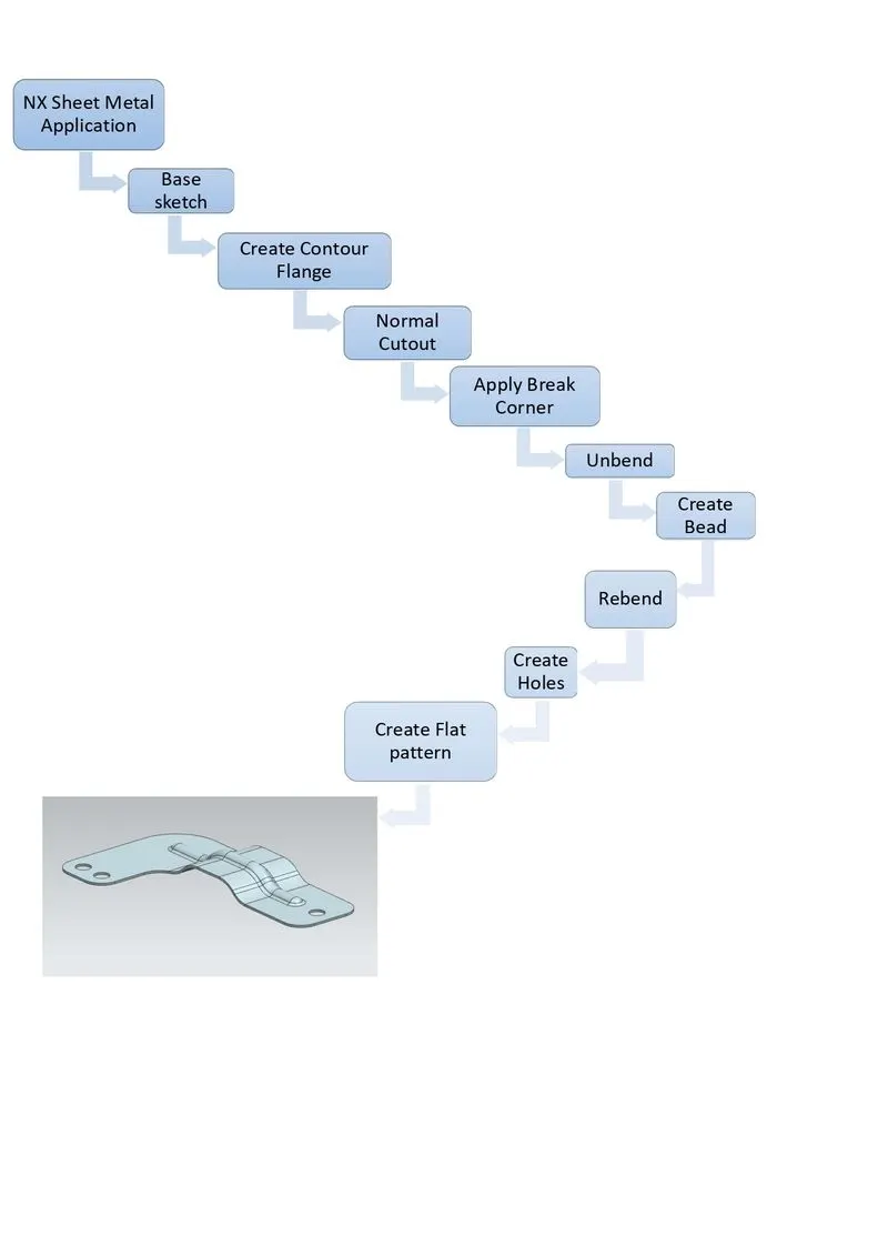
The design methodology used in this project is summarized in the following flow chart.
Description:
The following were commands used to model the bracket
- Base Sketch: This is the very basic element in any feature of the design of sheet metal components. This is the first step for the creation of a tab; therefore, it is called a base sketch.
- Contour Flange: It creates a base feature by extruding a sketch along a vector, or adds a material by sweeping a sketch along an edge or chain of edges.
- Normal Cut out: This feature cuts the material by projecting a sketch onto the model and then cutting perpendicular to the faces intersected by the projection.
- Break Corner: This is a feature, which rounds or chamfers a sharp corner of a tab or flange. This feature is similar to the fillet feature in some other CAD software.
- Unbend: It flattens a bend and the material adjacent to the bend. To achieve the flat configuration of the sheet metal as per the design intent, have to choose the bend in an order. Inbox selection of bend is also possible.
- Bead: This feature restores an unbend feature to its previous bent state, along with any features added after the unbend feature.
- Rebend: This feature restores an unbend feature to its previous bent state, along with any features added after the unbend feature.
- Holes: It adds a hole to one or more solid bodies in a part or assembly with options for counterbored, countersunk and threaded.
- Flat Pattern: It creates a flat pattern feature from the formed sheet metal part.
Procedure:
1) NX Sheet Metal Application:
Initially, NX sheet metal application was open to model the bracket
2) Create Base Sketch:
A base sketch was drawn on the XZ Plane with proper dimensions.
3) Create Contour Flange:
Based on the profile of the base sketch contour flange was created.
4) Normal Cut out:
Based on the sketch normal cut out was made to create the L shape of the bracket.
5) Apply Break Corner:
To avoid the stress concentration at the edges, break corners were provided at the necessary edges. This feature is similar to the fillet in the CAD software.
6) Unbend:
In this step, the sheet metal model was unbent to add other features like beads, dimples, and so on.
7) Create Bead:
A sketch consists of a line for the bead that was drawn on the XY plane and a bead was created with appropriate depth, radius and die radius.
8) Rebend:
Re- bend the sheet metal after adding the feature like bead by selecting face which previously used to create unbend.
9) Create Holes:
A sketch consisting of three points for hole creation was drawn on the XY plane at the required place.
Then the holes were created with the required dimensions.
10) Create a Flat pattern:
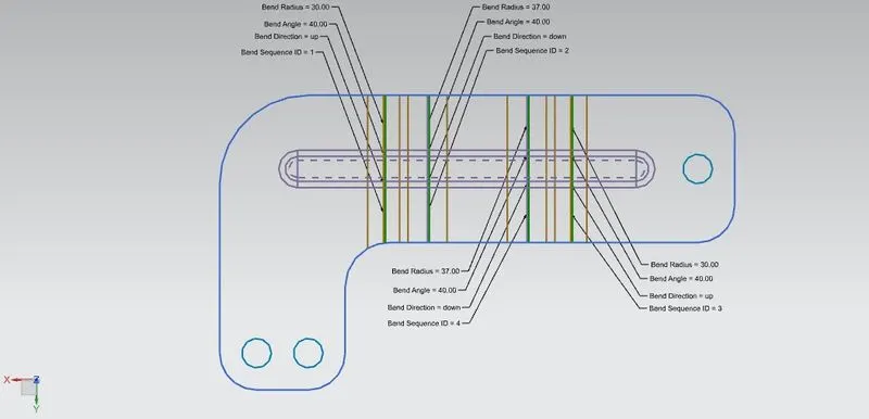
Using any flat surface of the model flat pattern was created.
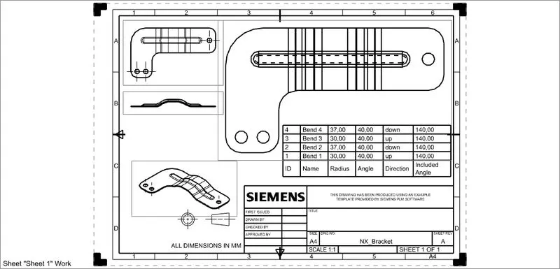
Then by opening the drafting application of the NX, the drafting file consists of tooling parameters such as bend table, bend angle, bend direction and so on was created.
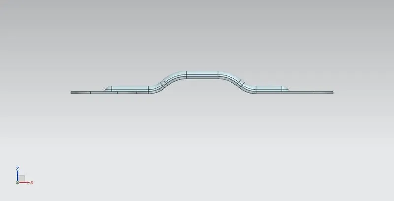
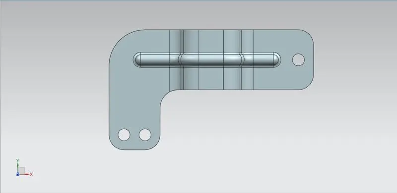
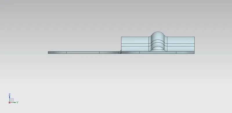
Different Views of the model:
1) Front View
2) Top View
3) Side View
4) Isometric View
5) Flat Pattern View
6) Drafting Sheet
Conclusion:
The sheet metal modelling of the bracket consisting of additional features like beads and holes was completed using Siemens NX sheet metal application.