Advanced Sheet Metal Design Using NX Cad Challenge_5_Odd Shaped Enclosure
DESIGNING OF ODD-SHAPED ENCLOSURE USING ADVANCED SHEET METAL
Objective:
To design the odd-shaped enclosure using the advanced sheet metal in Siemens NX Sheet Metal application.
Introduction:
Sheet metal is a metal formed by an industrial process into thin and flat parts. It is one of the basic forms used in metalworking, and it can be cut and bent into a variety of forms. Countless everyday objects are made of sheet metal.
In this project, an odd-shaped enclosure of sheet metal was designed to understand some of the advanced operations done in Siemens NX Sheet metal application. Various commands like Sheet metal from solid, Jog, dimple, and bead are used to model.
Design Methodology:
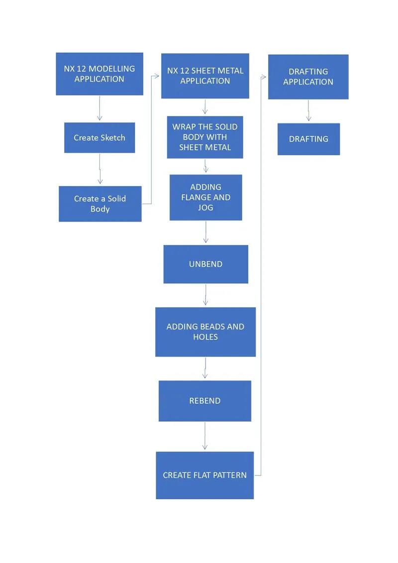
The design methodology used in this project is summarized in the following flow chart.
Description:
Initially in this project, the Siemens NX modelling application was opened to create a solid body of the enclosure.
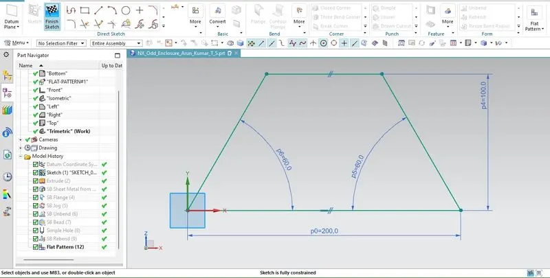
Sketch: This is the very basic element in any feature of the design of the sheet metal component. In this project, a sketch with the required dimension was drawn on the XZ plane of the datum CSYS.
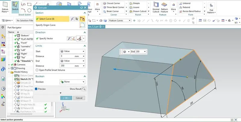
Extrude: This command creates a 3D projection of the profile. In this project, the drawn sketch was extruded to form a solid body of the enclosure with an odd shape.
Then the sheet metal application was switched and the rest of the sheet metal modelling was done here. The commands and procedures used in the model were discussed below.
Wrap the solid body with Sheet metal:
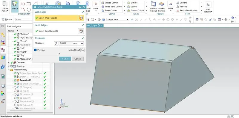
In this step, sheet metal wrapped on the solid body is created in modelling application.
Sheet metal from solid: This feature builds a sheet metal model that takes shape from a collection of planar faces.
Adding flange and jog:
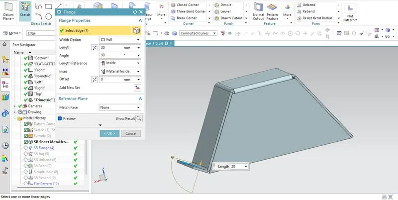
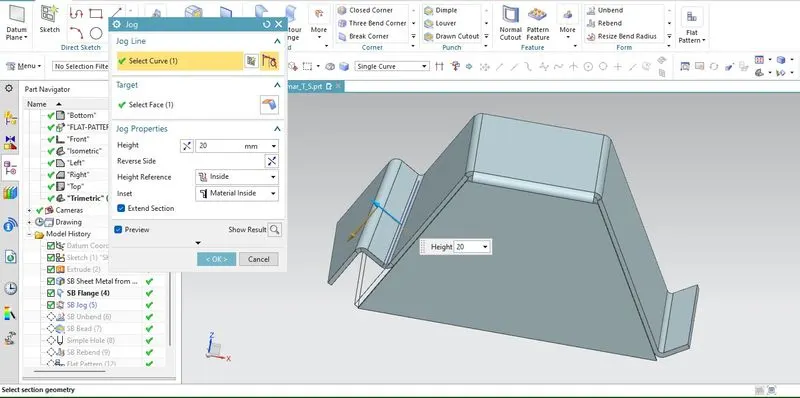
In this step, a flange and jog were added to the slant face of the sheet metal required dimensions
Flange: This feature adds a flat flange at an angle to a planar face and adds a bend between the two.
Jog: This feature modifies the model by lifting on one side of a sketch line, adding a flange between the two sides.
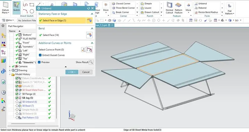
Unbend:
It flattens a bend and the material adjacent to the bend. To achieve the flat configuration of the sheet metal as per the design intent, have to choose the bend in an order. Inbox selection of bend is also possible. In this step, the sheet metal body was unbent to add other features like beads and holes.
Adding Beads and Holes:
Beads: This feature restores an unbend feature to its previous bent state, along with any features added after the unbend feature. In this project, beads were added to the required faces.

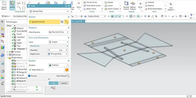
Holes: It adds a hole to one or more solid bodies in a part or assembly with options for counterbored, countersunk and threaded. In this project, a few holes are created as shown in the figure below.
Rebend: This feature restores an unbend feature to its previous bent state, along with any features added after the unbend feature.
Create a flat pattern:
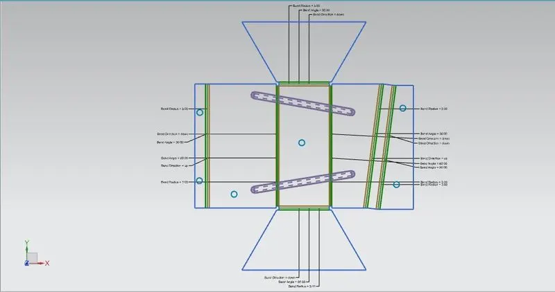
It creates a flat pattern feature from the formed sheet metal part. This 2d representation of the sheet metal model consists of all the tooling parameters. Flat patterns show bend lines, bend angles, bend radius, bend direction and the shape of the entire part with all bends flattened and bend factors considered.
Drafting:
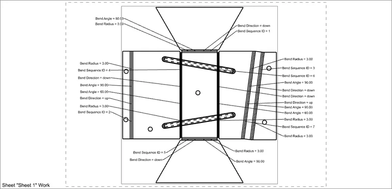
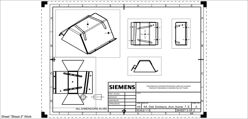
After the successful completion of the flat pattern to generate the drafting sheet switched to drafting application in the siemens NX. Once the design was completed, manufacturing of the component requires technical drawing with provided scale and accuracy. The necessary details such as bend table, annotations and other parameters were defined as per the requirement.
Different views of the model
1) Front View
2) Top View
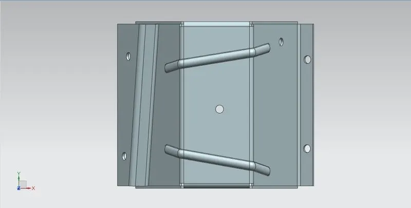
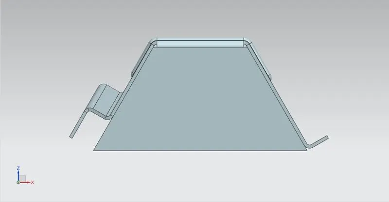
3) Side View
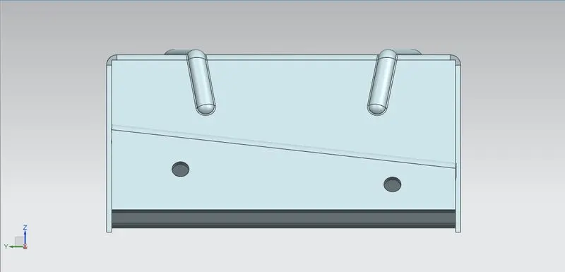
4) Isometric View
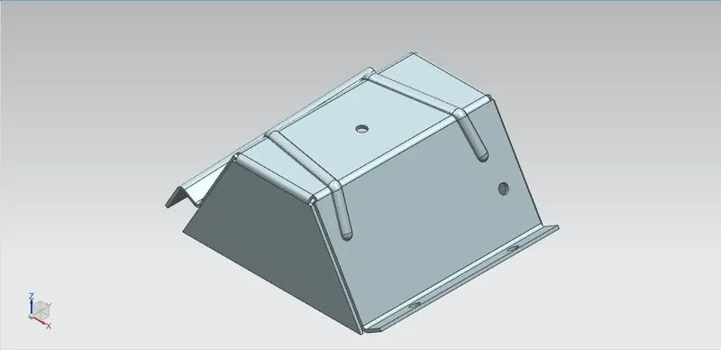
Conclusion:
Thus with the help of advanced features of the sheet metal like jog and sheet metal from solid sheet metal enclosure with odd shape was designed.