Modelling and Photo Realistic Rendering of American chopper
MODELLlING AND PHOTO REALSTIC RENDER OF AMERICAN CHOPPER
OBJECTIVE
The main objective of this project is to obtain a sustainable knowledge in SOLIDWORK part modelling,SOLIDWORK assembly and rendering Through ,
1)Modelling each part of the American chopper with proper Dimensions and apperance using SOLIDWORKS part
2)Assembling all the parts of American chopper using SOLIDWORK Assembly
3)Doing a Photo realistic render of American chopper using SOLIDWORKS Photo view 360 and SOLIDWORK Visualize
INTRODUCTION
Any product developed in an industry comes out to the customers starting all the way from the mind of a designer through the design process, simulation process , manufacturing and marketing.After understanding the customer need a Designer starts to design a model with the desired requirements using a Computer Aided Drawing softwares such as SOLIDWORKS , Siemens NX ,CATIA etc.Here in this project we are dealing with the widely used CAD software SOLIDWORKS.
SOLIDWORKS is a Solid modelling computer aided designing (CAD) and computer aided engineering (CAE) software, widely used for designing in manufacturing industries.We are Learning and Understanding Soliworks from the base through this project MODELING AND PHOTO REALISTIC RENDERING OF AMERICAN CHOPPER.
American chopper is a custom made bike using different parts of differnt bikes with some awesome features like elongated front forks , Low height sea etc.Selecting American Chopper As a model can help us to learn a lot of features of SOLIWORKS while modelling.
DESIGN METHODOLOGY/APPROACH
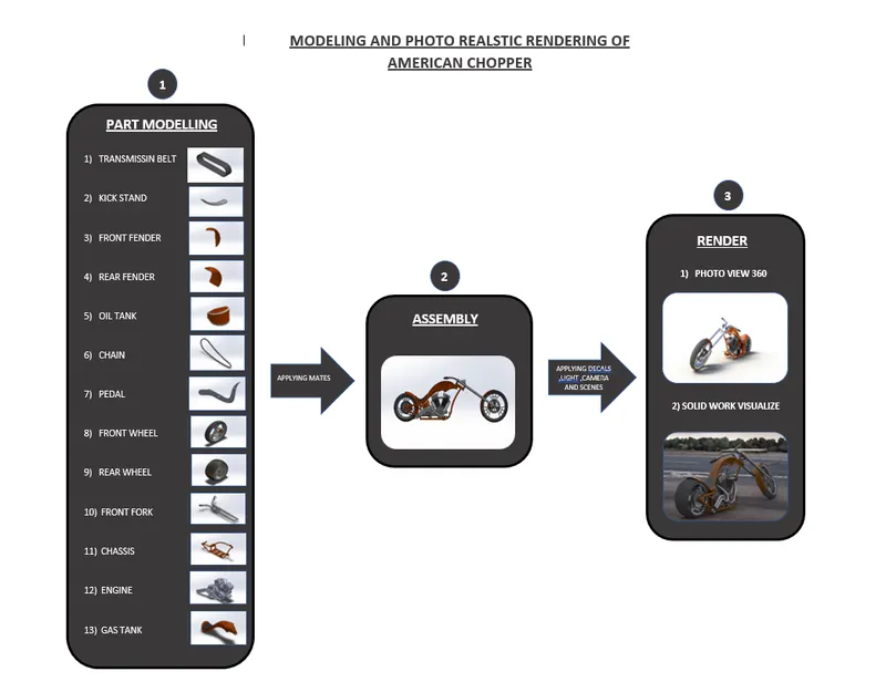
1) PART MODELLING
Parts are the building blocks of every SOLIDWORKS model where each assembly and render images are made from.Part modelLing is the process of creating individual 3D components(parts) from 2D sketches using SOLIDWORKS features like Extrude boss,Revolve boss etc.
The individual components created for this project are
- Transmission belt
- Kick stand
- Front fender
- Rear fender
- Chain
- Oil tank
- Pedal
- Front wheel
- Rear wheel
- Front fork
- Chassis
- Engine
- Gas tank
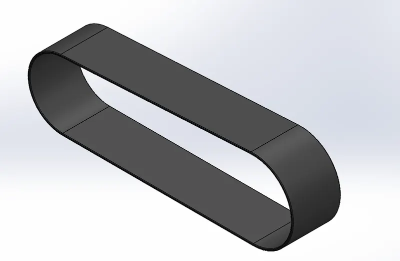
TRANSMISSION BELT
Transmission belt is a loop of flexible material used to link two or more rotating shafts mechanically inorder to transmit power.
View Part : https://drive.google.com/file/d/1TXMM1ujQglCLZ5HQQAaYwdU1HQk6e9oB/view?usp=sharing
Tools used
- Line tool: Line tool is used to draw lines and arcs in the sketches
- Smart dimensions: To add or edit dimensions of sketches
Features used
- Extruded Boss/Base: It is the feature which allows to take a 2D sketch and add thickness to it in the third dimension.
- Fillet : Fillet is the feature used to create rounded internal or external faces in the edges of the parts
- Appearance: Appearance is the option in solid works used to change the appearance of the 3D models.Appearance can be applied to a body or a single feature in that body
Procedure
Using Line and Arc constraints create the 2D sketch of the transmission belt and offset it outward with the dimensions given ,then Extrude the sketch to specified thickness.Apply proper fillet to each edges of the transmission belt.Now give an appearance to the model such as matt rubber or glossy rubber and save the part with the name transmission belt
KICK STAND
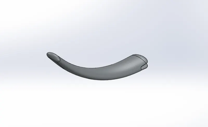
Kick stand is a Supporting Mechanism which is used to prevent the chopper lean on ground and makes upright with out interfere with a person or Object
View Part : https://drive.google.com/file/d/1s5vtuah6Ac3Ys2CSbVjf9RB4eWOegcpD/view?usp=sharing
Tools used
- Ellipse : Elipse is a drawing tool used create elipse shapes in sketches
- Spline : Spline tool allow the user to create organic,curvature continuous,complex curves.
- Center point rectangle: It is used to make Rectangle based on its center point
- Smart dimensions: To add or edit dimensions of sketches
Features used
- Lofted Boss/Base : The loft feature is an important tool for (surface) modeling in SolidWorks. The loft feature creates a shape by making transitions between multiple profiles and guide curves. This tool is very valuable for modeling complex surfaces
- Fillet : Fillet is the feature used to create rounded internal or external faces in the edges of the parts
- Dome: The feature used to create dome shapes in the surfaces
- Extruded Cut: This feature allows to easly remove material from a solid by extruding a profile along the normal to its plane
- Split : The split line feature is used to project an entity(sketch,solid,surface,plane,or surface spline) onto other surfaces or curved/planar faces
Procedure
Using elipse tool create an elipse in front plane with specified dimension.Draw a spline in the right plane using spline tool that starts from centre of the elipse with the proper dimensions.Then create another plane at the one end of the spline and draw another elipse in that newly created plane.Using lofted boss base feature creature a loft profile from one elipse to the other by making the spline as center line parameter.Now create two domes at each side of the lofted profile by using dome feature and save the part
FRONT FENDER
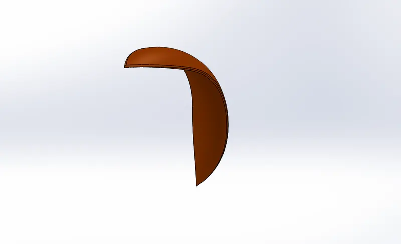
Fenders make a tremendous difference when riding on roads that are wet from drizzle, recent rain, or snowmelt. In a hard rain, fenders will protect rider body and bike from the mud and sand kicked up from dirty puddles and rivulets.Front fender is the fender which is mounded to the front wheel
View Part : https://drive.google.com/file/d/1wi8fyIA-mBt0dBac2Yfl-3MoSpEExW__/view?usp=sharing
Tools used
- 3 point Arc : 3point arc tool is used to draw arcs with center point as the reference Point.
- Spline : Spline tool allow the user to create organic,curvature continuous,complex curves.
- Dynamic mirror : Dynamic mirror is the tool which allows the user to mirror a sketch about a line while the user is creating the sketch
- Offset entities : The tool used create sketch offset.
- Extent entities : It is used to extend entities to meet another sketch entity.
- Trim entities : Trim is used to trim/delete sketch entities
- Smart dimensions: To add or edit dimensions of sketches
Features used
- Revolve boss/base : Revolve boss add material by revolving one or more profiles around an axis
- Split : The split line feature is used to project an entity(sketch,solid,surface,plane,or surface spline) onto other surfaces or curved/planar faces
- Fillet : Fillet is the feature used to create rounded internal or external faces in the edges of the part.
- Appearance: Appearance is the option in solid works used to change the appearance of the 3D models.Appearance can be applied to a body or a single feature in that body
Procedure
Draw a 3 point arc with its center point vertical to the origin and the given distance away from the origin.Offset the sketch inward with proper dimension ,draw two vertical lines from each end of the upper arc with the desired dimension.Make the sketch closed using extent entities and then revolve it about the axis up to the given dimension.Then draw the sketch to split extra material from the fender with proper dimensions and remove the extra material by using split feature.Apply fillet to all of the edges with proper dimension and Save the part
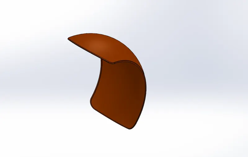
REAR FENDER
As the front fender The rear fender will also protect rider body and bike from the mud and sand kicked up from dirty puddles and rivulets but it is mounded to the rear wheel
View Part : https://drive.google.com/file/d/1n_-Z5iRLa141LNojw_AboCf4f9Cg8eP-/view?usp=sharing
Tools used
- 3 point Arc : 3point arc tool is used to draw arcs with center point as the reference Point.
- Spline : Spline tool allow the user to create organic,curvature continuous,complex curves.
- Dynamic mirror : Dynamic mirror is the tool which allows the user to mirror a sketch about a line while the user is creating the sketch
- Offset entities : The tool used create sketch offset.
- Extent entities : It is used to extend entities to meet another sketch entity.
- Trim entities : Trim is used to trim/delete sketch entities
- Smart dimensions: To add or edit dimensions of sketches
Features used
- Revolve boss/base : Revolve boss add material by revolving one or more profiles around an axis
- Split : The split line feature is used to project an entity(sketch,solid,surface,plane,or surface spline) onto other surfaces or curved/planar faces
- Fillet : Fillet is the feature used to create rounded internal or external faces in the edges of the parts
- Appearance: Appearance is the option in solid works used to change the appearance of the 3D models.Appearance can be applied to a body or a single feature in that body
Procedure
The procedure to create rear fender is same as the front fender but here the dimensions only changes
CHAIN
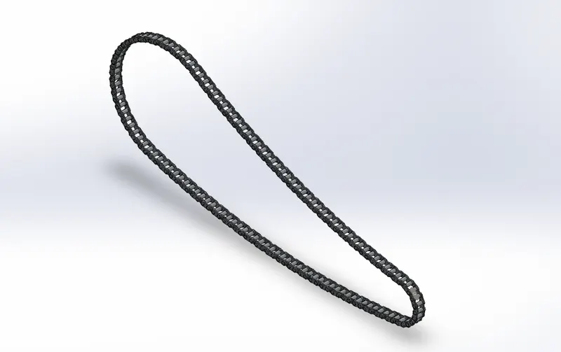
Chain is the part of the bike with transmits power from the engine to the wheels of the bike and the mechanism is called chain drive
View Part : https://drive.google.com/file/d/1M0DF5lqQBLUYWHHOUlr1Py39ImHiaa1T/view?usp=sharing
Tools used
- 3 point Arc : 3point arc tool is used to draw arcs with center point as the reference Point.
- Circle : Tool used to draw circle sketches
- Trim entities : Trim is used to trim/delete sketch entities
- Blocks : Sketch Blocks within your SolidWorks sketches provide a simple, but powerful method of grouping objects together. Blocks are manipulated as one object, including constraining and dimensioning as other sketch entities.
- Smart dimensions: To add or edit dimensions of sketches
Features used
- Extruded Boss/Base: It is the feature which allows to take a 2D sketch and add thickness to it in the third dimension.
- Fillet : Fillet is the feature used to create rounded internal or external faces in the edges of the parts
- Curve Driven Pattern : The Curve Driven Pattern tool allowsus to create patterns along a planar or 3D curve. To define the pattern, you can use any sketch segment, or the edge of a face (solid or surface), that lies along the plane. We can base our pattern on an open curve, or on a closed curve, such as a circle.
- Appearance: Appearance is the option in solid works used to change the appearance of the 3D models.Appearance can be applied to a body or a single feature in that body
Procedure
A Chain includes three parts which are Chain plates (inner plate &outer plate) and pins.So we need to sketch them individualy and save each of them as different sketch blocks.First of all sketch the inner plate by using circles and 3point arcs with proper dimensions and constraints and save it as a block with name inner plate.Outer plates for the chain is also created in the same way ,but here sketch for the pins are also included .After saving the blocks, draw two circles in the front plane with specified diameter and specified distance horizontaly away from each other.Now draw an arc with two end points of the curve touching the top quadrants of the circles.Draw another arc touching the bottom quadrants of the circle and remove extra sketches that we don’t need ,this is the path where the blocks should be placed,.Then place the blocks appropriately over the sketch that just created and extrude them well with the given dimensions.Then using the curve driven pattern option pattern it all over the sketch,and then save the part.
OIL TANK
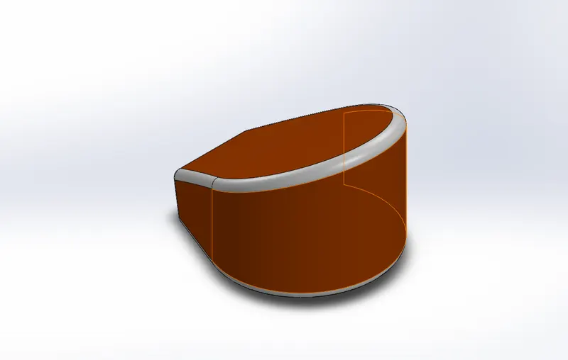
Oil is needed for every vehicles in their engines to reduce temperature and to reduce friction between the moving parts.The reservoir for this oil is called oil tank
View Part : https://drive.google.com/file/d/1oqlIIaL293_iA0_hdzQvwAsg2K6EQfOu/view?usp=sharing
Tools used
- Line tool: Line tool is used to draw lines and arcs in the sketches
- 3 point Arc : 3point arc tool is used to draw arcs with center point as the reference Point
- Spline : Spline tool allow the user to create organic ,curvature continuous or complex curves.
- Dynamic mirror : Dynamic mirror is the tool which allows the user to mirror a sketch about a line while the user is creating the sketch
- Smart dimensions: To add or edit dimensions of sketches
Features used
- Extruded Boss/Base: It is the feature which allows to take a 2D sketch and add thickness to it in the third dimension.
- Combine : The option to add two or more bodies togather
- Fillet : Fillet is the feature used to create rounded internal or external faces in the edges of the parts
- Shell : The shell tool hollows out a part, leaves open the faces you select, and creates thin-walled features on the remaining faces. If we do not select any face on the model, we can shell a solid part, creating a closed, hollow model. We can also shell a model using multiple thicknesses.
- Appearance: Appearance is the option in solid works used to change the appearance of the 3D models.Appearance can be applied to a body or a single feature in that body
Procedure
Start sketching a horizontal construction line in the specific plane from the origin.Then turn on the dynamic mirror option and start drawing the sketches of the oil tank using line and arc tool with proper dimensions.Extrude the sketch to needful thickness specified.Now draw another sketch using spline and line tool in-order to complete the shape of the oil tank.Extrude it well and Combine them using combine option and keep the geometry in common.Then apply suitable fillets to all edges of the solid body created.Then using shell option create a hollow cavity inside this solid body and save the part as oil tank
PEDAL
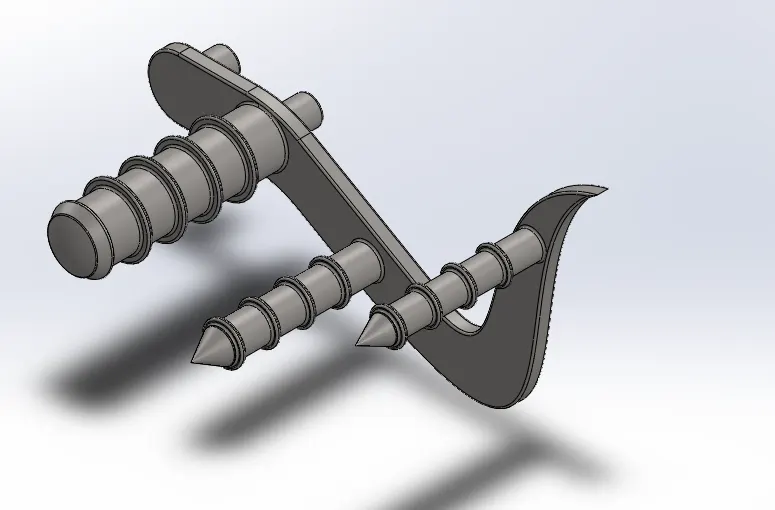
Pedals are the structures which support the foots(foot rest) whille riding
View Part : https://drive.google.com/file/d/1iA7skBvDYHiiO6PA-4YjXDI6tj0ztmHv/view?usp=sharing
Tools used
- Line tool: Line tool is used to draw lines and arcs in the sketches
- Spline : Spline tool allow the user to create organic ,curvature continuous or complex curves.
- Circle : Tool used to draw circle sketches
- Offset entities : The tool used create sketch offset.
- 3 point Arc : 3point arc tool is used to draw arcs with center point as the reference Point
- Smart dimensions: To add or edit dimensions of sketches
Features used
- Extruded Boss/Base: It is the feature which allows to take a 2D sketch and add thickness to it in the third dimension
- Revolve boss/base : Revolve boss add material by revolving one or more profiles around an axis
- Linear Pattern : The option used to create a pattern of feature or body along a linear reference
- Dome: The feature used to create dome shapes in the surfaces
- Chamfer : The chamfer tool creates a beveled feature on selected edges, faces, or a vertex. ... Set the Distance and Angle in the Chamfer Property Manager or in the graphics area. A manipulator arrow appears that points in the direction in which the distance is measured.
Procedure
Sketch the frame of the pedal in 2D in the required plane using tools like spline and 3 ponit arc,then draw four cicles and place it over the sketch of the frame where the foot pegs and pins are needed. Now extrude the frame to specific thickness,after that extrude the circles (which are the two foot pegs and two pins) to suitable length.Using revolve feature create the main foot peg (thickest foot peg) with specific dimension.Create a sketch of two circles which is concentric to the main foot peg and extrude it to specified distance offset from the frame of the pedal, this is to create fin like projections on the foot pegs .And then using linear pattern, pattern the projection along the foot peg as needed .Do the same in the other two foot pegs with suitable dimension.Add a dome at the end face of the main foot peg while applying chamfer to other two foot pegs.Add suitable fillet to the frame and the projections in the foot pegs.Now save the part in the name PEDAL
FRONT WHEEL
A wheel is a circular shaped structure where the tyre of the vehicle is mounted.They are the only structure of an entire vehicle in contact with the ground,thus it rotates on an axis and helps to moves the vehicle .It consist of a rim,hub and spokes.Wheel mounted on front side of a vehicle is called front wheel.Here we are creating wheel including rim,rotor,calipper and tyre
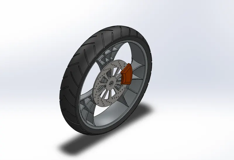
View Part : https://drive.google.com/file/d/1CdkYuqrSo4ETWeNMYmH_CaB4DW1xjEnl/view?usp=sharing
Tools used
- Line tool: Line tool is used to draw lines and arcs in the sketches
- Spline : Spline tool allow the user to create organic ,curvature continuous or complex curves.
- 3 point Arc : 3point arc tool is used to draw arcs with center point as the reference Point
- Smart dimensions: To add or edit dimensions of sketches
- Extent entities : It is used to extend entities to meet another sketch entity.
- Trim entities : Trim is used to trim/delete sketch entities
- Sketch fillet : Creates round corners instad of sharp corners
- Offset entities : The tool used create sketch offset
Features used
- Extruded Boss/Base: It is the feature which allows to take a 2D sketch and add thickness to it in the third dimension
- Revolve boss/base : Revolve boss add material by revolving one or more profiles around an axis
- Linear Pattern : The option used to create a pattern of feature or body along a linear reference
- Circular Pattern : The option used to create a pattern of feature or body along a circular reference
- Chamfer : The chamfer tool creates a beveled feature on selected edges, faces, or a vertex. ... Set the Distance and Angle in the Chamfer Property Manager or in the graphics area. A manipulator arrow appears that points in the direction in which the distance is measured.
- Extruded Cut: This feature allows to easly remove material from a solid by extruding a profile along the normal to its plane
- Combine : The option to add two or more bodies togather
- Fillet : Fillet is the feature used to create rounded internal or external faces in the edges of the parts.
- Appearance: Appearance is the option in solid works used to change the appearance of the 3D models.Appearance can be applied to a body or a single feature in that body
Procedure
Rim : Draw the sketch in the specified plane with given dimensions ,using revolve feature revolve the sketch about the axis created using a construction line.After achiving the rim and hub add spider spokes to the rim .Using extrude boss and extrude cut option create a set of spokes and pattern it circulary on the rim with an instance of 3.Now add suitable fillets to the spokes edges and thus the rim with spokes and hub are created
Rotor : The rotor here is the Front brake disk plate of the bike which is created by extruding a circle with specified dimension .After that using cut extrude option make tiny holes in the rotor in a linear pattern.Now create a circlular pattern using the set of circles created and the rotar is ready
Calipper : Sketch the shape of the caliper on the surface of the rotor and extrude it to the specified thickness.applt chamfer to the edges with appropriate dimensions
Tyre : Tyre is created in the same way that the rim is created.Using revolve feature Revolve the sketch to get the tyre with specified dimension.After that “extrude” cut some material appropriately from the tread of the tyre to make tyre pattern.Then pattern the “cut” circularly over the tyre.
Combine alle this parts together and make a single solid body except rotor and calipper and save the part as front wheel
REAR WHEEL
It is the wheel of the bike where the power from the engine is transmitted to by means of chain
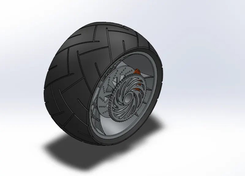
View Part : https://drive.google.com/file/d/1ejx2a138tNPsBjkOaRk77gvxi2FXm4yZ/view?usp=sharing
Tools used
- Line tool: Line tool is used to draw lines and arcs in the sketches
- Spline : Spline tool allow the user to create organic ,curvature continuous or complex curves.
- 3 point Arc : 3point arc tool is used to draw arcs with center point as the reference Point
- Smart dimensions: To add or edit dimensions of sketches
- Extent entities : It is used to extend entities to meet another sketch entity.
- Trim entities : Trim is used to trim/delete sketch entities
- Sketch fillet : Creates round corners instad of sharp corners
- Offset entities : The tool used create sketch offset
Features used
- Extruded Boss/Base: It is the feature which allows to take a 2D sketch and add thickness to it in the third dimension
- Revolve boss/base : Revolve boss add material by revolving one or more profiles around an axis
- Linear Pattern : The option used to create a pattern of feature or body along a linear referenceCircular Pattern : The option used to create a pattern of feature or body along a circular reference
- Chamfer : The chamfer tool creates a beveled feature on selected edges, faces, or a vertex. ... Set the Distance and Angle in the Chamfer Property Manager or in the graphics area. A manipulator arrow appears that points in the direction in which the distance is measured.
- Extruded Cut: This feature allows to easly remove material from a solid by extruding a profile along the normal to its plane
- Combine : The option to add two or more bodies togather
- Fillet : Fillet is the feature used to create rounded internal or external faces in the edges of the parts
- Appearance: Appearance is the option in solid works used to change the appearance of the 3D models.Appearance can be applied to a body or a single feature in that body
Procedure
Procedure to create rear wheel is same to the procedure of front wheel.The only difference is there is sprocket extra in this part.Create the sprocket by extruding a circle to needed thickness,then chamfer the outer edges of the circular plate with given dimension.Now create the teeths and the hollow cuts using extrude cut feature.Now give appropriate appearance and save the part
FRONT FORK
The “fork” is the suspension at the front of a motorcycle in nearly every motorcycle available today, the front wheel is held on by an axle that's connected to the fork. It's called a fork because it has two prongs that go around each side of the wheel.
Here we are creating front fork along with the handle bars, brake livers and the front lights
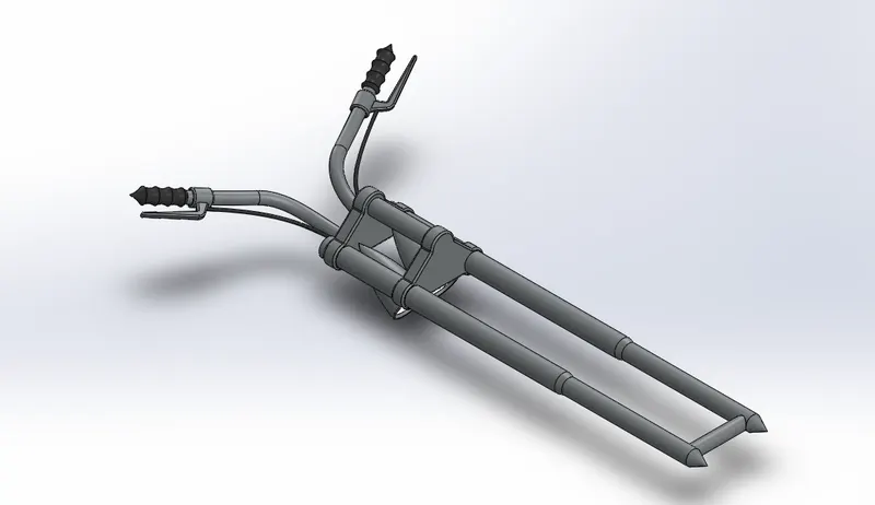
View Part : https://drive.google.com/file/d/1lUfR5IwPEQU8OV84VkOIO662AyPnltr5/view?usp=sharing
Tools used
- Line tool: Line tool is used to draw lines and arcs in the sketches
- Spline : Spline tool allow the user to create organic ,curvature continuous or complex curves.
- 3 point Arc : 3point arc tool is used to draw arcs with center point as the reference Point
- Smart dimensions: To add or edit dimensions of sketches
- Circle : Tool used to draw circle sketches
- Projected curve : A projected cure is the projection of two curves,ie it is the intersection of the surface created by two curves
- Convert entity : The Convert Entities tool allows users to make a copied projection of a given sketch, face, or set of edges onto the active sketch plane.
Features used
- Extruded Boss/Base: It is the feature which allows to take a 2D sketch and add thickness to it in the third dimension
- Revolve boss/base : Revolve boss add material by revolving one or more profiles around an axis
- Combine : The option to add two or more bodies together
- Fillet : Fillet is the feature used to create rounded internal or external faces in the edges of the parts
- Appearance: Appearance is the option in solid works used to change the appearance of the 3D models.Appearance can be applied to a body or a single feature in that body
- Mirror : Used to mirror a body or a feature about a plane
- Movecopy body : This feature is used to move/copy a body to one place to another pace
- Split : The split line feature is used to project an entity(sketch,solid,surface,plane,or surface spline) onto other surfaces or curved/planar faces
Procedure
Start by modelling a single cylinder of the front fork. Create the sketch of the cylinder with line tool and revolve it about its centre using Revolve feature. Then create the half (in-order to mirror) of the crown by extruding the proper sketch in proper plane. Now draw an axis to mirror the solid bodies, with a construction line .Mirror the solid bodies about the axis just created. Then create the shaft for the front wheel by extruding the proper sketch. Add head light to the fork by revolving the appropriate sketch and mirror it about the same axis that we created to mirror the cylinder.
After modelling the forks create projection curve for the handle bar and sweep a suitable path along the projected with proper dimensions. Mirror the handle bar to the other side .Create grips in the handles using revolve feature. Last extrude the brake livers with proper dimension and create the brake cables using sweep tool along the specified projected curve. Now apply suitable fillets and appearance and then save the part as front fork
CHASSIS
A motorcycle's chassis or frame forms its skeleton. All the components of a motorcycle, like the suspension, wheels, engine,fuel tank, seats, handlebars etc, are attached to this base structure which lends a motorcycle its strength and ability to handle well

View Part : https://drive.google.com/file/d/14-LH2Hj1YWoWj2txKB4Lr0XYlS-HWYTI/view?usp=sharing
Tools used
- Line tool: Line tool is used to draw lines and arcs in the sketches
- Spline : Spline tool allow the user to create organic ,curvature continuous or complex curves.
- Smart dimensions: To add or edit dimensions of sketches
- Circle : Tool used to draw circle sketches
- Projected curve : A projected cure is the projection of two curves,ie it is the intersection of the surface created by two curves
- Convert entity : The Convert Entities tool allows users to make a copied projection of a given sketch, face, or set of edges onto the active sketch plane.
Features used
- Extruded Boss/Base: It is the feature which allows to take a 2D sketch and add thickness to it in the third dimension
- Sweep Boss/Base : Within SOLIDWORKS, a sweep is a tool that creates a solid, a cut or a surface feature by moving a profile along a path. To create a solid, use the Swept Boss tool to move a profile along a path. The profile can contain one or more closed contours.
- Mirror : Used to mirror a body or a feature about a plane
- Combine : The option to add two or more bodies togather
- Fillet : Fillet is the feature used to create rounded internal or external faces in the edges of the parts
- Appearance: Appearance is the option in solid works used to change the appearance of the 3D models.Appearance can be applied to a body or a single feature in that body
- Extruded Cut: This feature allows to easly remove material from a solid by extruding a profile along the normal to its plane
Procedure
For modelling the chassis we are taking the blueprint of the American chopper as reference.Draw the proper sketch to create the projected curves .Sweep the circle with specified dimension along the projected curves .Model the half of the chassis and mirror it to get the full frame.Now using extrude feature extrude the supporting structure for the engine.Also revolve the neck “the structure to mount front fork” and extrude the proper structure to mount kick stand.Now give proper appearance and save the part with the name chassis
ENGINE
The engine , can say the heart of a motor vehicle. It is a complex machine built to convert heat from burning gas into the force that turns the road wheels. ... It consists of two basic parts: the lower, heavier section is the cylinder block, a casing for the engine's main moving parts; the detachable upper cover is the cylinder head.
Here we are creating engine along with exhaust mufflers.
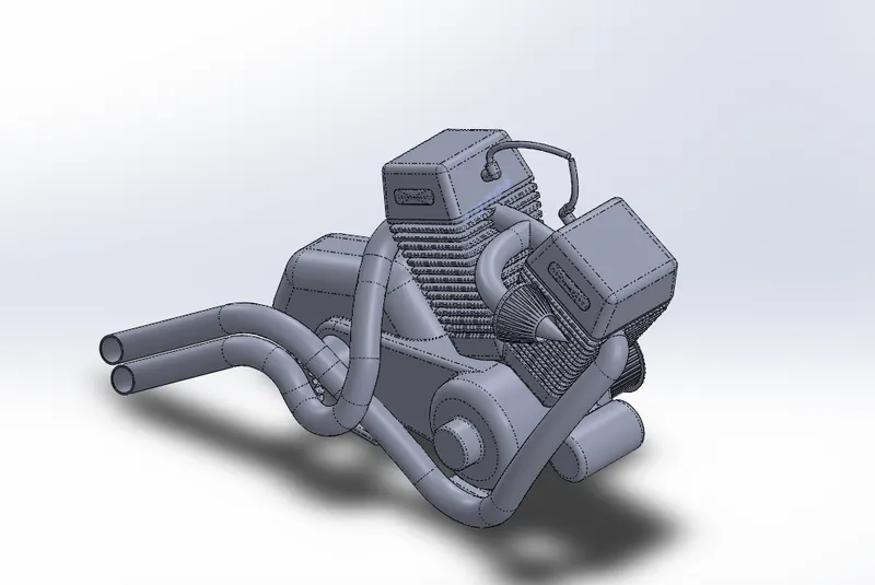
View Part : https://drive.google.com/file/d/10kzDRhB8pY3wWoDlbq5937UMBpI8kasb/view?usp=sharing
Tools used
- Line tool: Line tool is used to draw lines and arcs in the sketches
- Spline : Spline tool allow the user to create organic ,curvature continuous or complex curves.
- 3 point Arc : 3point arc tool is used to draw arcs with center point as the reference Point
- Smart dimensions: To add or edit dimensions of sketches
- Extent entities : It is used to extend entities to meet another sketch entity.
- Trim entities : Trim is used to trim/delete sketch entities
- Sketch fillet : Creates round corners instad of sharp corners
- Offset entities : The tool used create sketch offset
- Projected curve : A projected cure is the projection of two curves,ie it is the intersection of the surface created by two curves
- Convert entity : The Convert Entities tool allows users to make a copied projection of a given sketch, face, or set of edges onto the active sketch plane.
- Composite curve : The tool used to composite two ore more individual curve
Features used
- Extruded Boss/Base: It is the feature which allows to take a 2D sketch and add thickness to it in the third dimension
- Revolve boss/base : Revolve boss add material by revolving one or more profiles around an axis
- Sweep Boss/Base : Within SOLIDWORKS, a sweep is a tool that creates a solid, a cut or a surface feature by moving a profile along a path. To create a solid, use the Swept Boss tool to move a profile along a path. The profile can contain one or more closed contours.
- Extruded Cut: This feature allows to easly remove material from a solid by extruding a profile along the normal to its plane
- Combine : The option to add two or more bodies togather
- Fillet : Fillet is the feature used to create rounded internal or external faces in the edges of the parts
- Appearance: Appearance is the option in solid works used to change the appearance of the 3D models.Appearance can be applied to a body or a single feature in that body
- Mirror : Used to mirror a body or a feature about a plane
- Linear Pattern : The option used to create a pattern of feature or body along a linear reference
- Circular Pattern : The option used to create a pattern of feature or body along a circular reference
- Chamfer : The chamfer tool creates a beveled feature on selected edges, faces, or a vertex. ... Set the Distance and Angle in the Chamfer Property Manager or in the graphics area. A manipulator arrow appears that points in the direction in which the distance is measured.
- Dome: The feature used to create dome shapes in the surfaces
Procedure
Engine is the most complex part which we are modelling among all the other parts in chopper.As in the chassis here also we are using the blue print of Here we are using almost all the features and tools that we have used in previous part modelling.For creating the crank and ,draw the sketch with proper dimension and constraints and extrude it to the specified thickness.Then the fins are created around the cylinder using extrude cut option.Using extrude cut make a rectangular cut around the cylinder and then pattern it linearly over the cylinder.Create a dome projection in cylinder head using dome option and the given dimensions.
After completing the modelling of one cylinder mirror it and make the engine a 2 cylinder engine.Using the revolve boss option create 2 pulleys in the right side of the engine which are the pulleys for the transmission belt .Make rectangular cuts in the pulleys using extrude cut feature
At the left side of the engine a sprocket is extruded with specified dimensions .Teeth’s of the sprocket are made by applying fillet to the extruded plate and circularly patterning a specific extrude cut .Air filter is made by using revolve option and cutting in the filter are made by extrude cut option.Now create the projected curves for the exhaust muffler and make the curves composite.Sweep the specific profile along the composite curves to achieve the exhaust muffler.After creating every components in the engine give the suitable appearance and save the part
GAS TANK
A fuel tank (also called a petrol tank or gas tank) is a safe container for flammable fluids. Though any storage tank for fuel may be so called, the term is typically applied to part of an engine system in which the fuel is stored and propelled (fuel pump) or released (pressurized gas) into an engine.
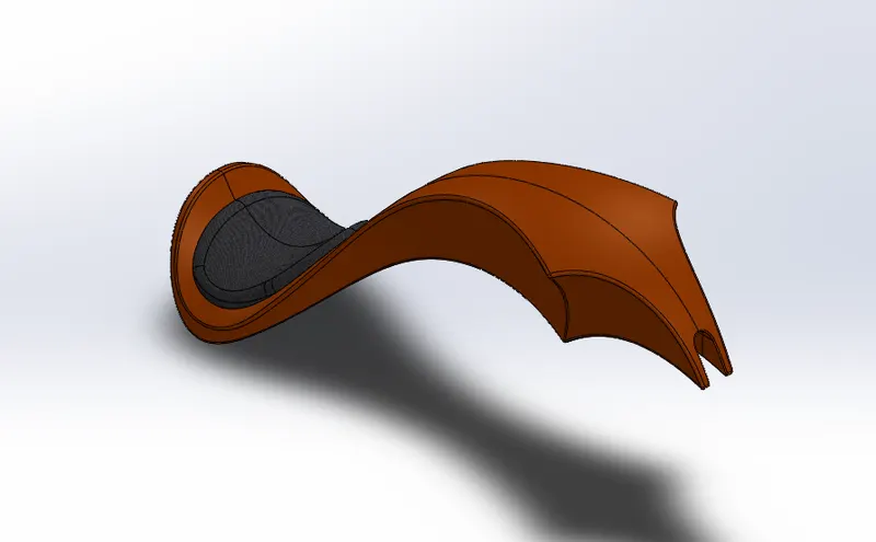
View Part : https://drive.google.com/file/d/1W1zLxfu61aSgyFoBnovpSjbqoFH3LVfV/view?usp=sharing
Tools used
- Line tool: Line tool is used to draw lines and arcs in the sketches
- Spline : Spline tool allow the user to create organic ,curvature continuous or complex curves.
- Projected curve : A projected cure is the projection of two curves,ie it is the intersection of the surface created by two curves
- Convert entity : The Convert Entities tool allows users to make a copied projection of a given sketch, face, or set of edges onto the active sketch plane.
Features used
- Sweft Surface : It if a surface feature used to generate surfaces using section curves positioned along a path
- Boundary surface : The boundary surface feature lets you create surfaces that can be tangent or curvature continuous in both directions (all sides of the surface).
- Loft Surface : Loft Surfaces are surfaces generated by multiple 3D Curves or existing edges creating a smooth tangency between the selected curves.Loft Surface is the tool used to create a lofted surface.
- Knit surface : Feature used to combine two or more surfaces in to one
- Swept cut : Swept cut is a feature to remove materials of abody along a sweep path
- Shell : The shell tool hollows out a part, leaves open the faces you select, and creates thin-walled features on the remaining faces. If we do not select any face on the model, we can shell a solid part, creating a closed, hollow model. We can also shell a model using multiple thicknesses.
- Appearance: Appearance is the option in solid works used to change the appearance of the 3D models.Appearance can be applied to a body or a single feature in that body
- Fillet : Fillet is the feature used to create rounded internal or external faces in the edges of the parts
Procedure
With the help of the blue print create all the projected curves for making the surfaces of the gas tank. Using the tools like sweep surface ,loft surface, boundary surface create the entire structure of the gas tank. Then create the seat of the chooper above the tank using surface extrude option with specified dimensions.Now create a swept cut along the centre of the tank with specified dimension in-order to mount the tank on the chassis.Now apply proper appearance and save the part in the name gas tank
2)ASSEMBLY OF AMERICAN CHOPPER
Assembly is one of the main feature of SOLIDWORK which allows us to assemble the individual parts using an option called assembly mates
Assembly mates are the geomatric relations (such as coincident ,concentric ,parallel etc.) applied between different parts while assembling them.In solid work three types og mates than we can use. They are
- Standard mate : They are the common geomatric relations such as concentric , coincident,parallel etc
- Advanced mate : This option allows us to decide the distance between the components ,angle between the components etc.
- Mechanical mate : To make things simpler, SOLIDWORKS has a set of mates, called mechanical mates, that can be used to mimic real-world interaction that might be difficult to simulate with just the standard mates. We can use mechanical mates for components such as cams, gears, and universal joints.
Here we are assembling the AMERICAN CHOPPER with all the individual components ” that we created using SOLIDWORK part” using mates feature in SOLIDWORK assembly
For the assembly of chopper we are only applying standard mates and advanced mates
Procedure
First create a new assembly document in solidworks.Using insert component option insert the chassis as the first component and make it folat (Float is the option to unfix the component from any plane).After that insert all other components and properly mate it with the chassis.Remeber to not apply any mates of any components with the assembly planes because it disables the permission to position the chopper as we need to.After inserting all the components and applying proper mates save the part as ASSEMBLY CHOPPER.
The different views (1.front view , 2.isomatric view , 3.right side view , 4.top view & 5.camera view) of assembled chopper is given below
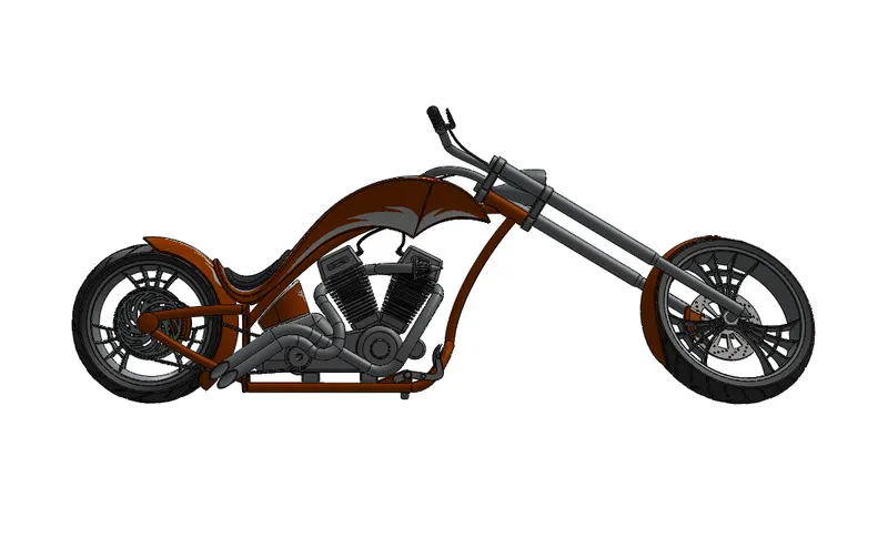
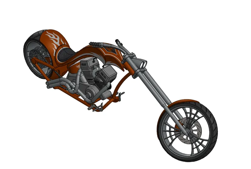
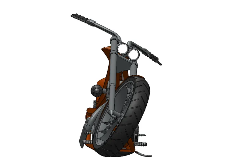

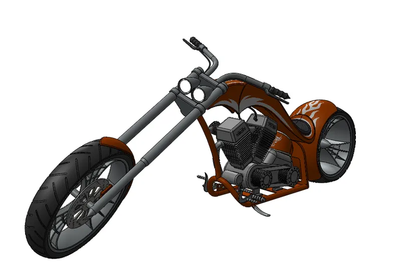
View Assembly : https://drive.google.com/file/d/1t5TL7gharwy3LU4kkMnB9KNCN8sq_LXD/view?usp=sharing
3)RENDERING OF AMERICAN CHOPPER
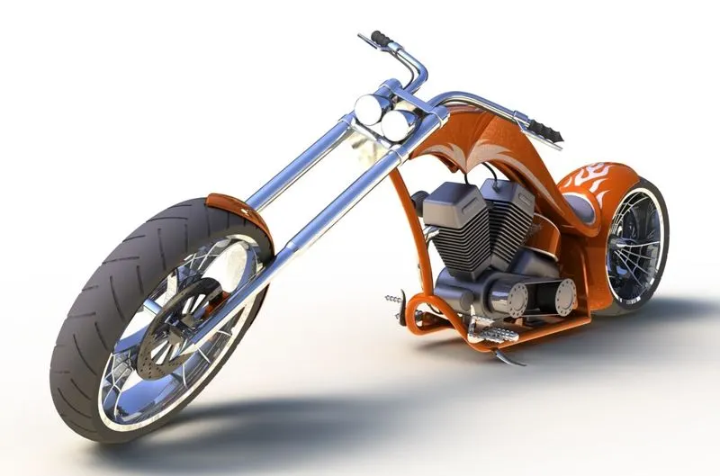
Rendering is the process of creating HyperRealistic images of the components/assembly.Here we are using SOLIWORK add-ins such as SOLIWORK Photo view 360 and SOLIDWORK Visualize to render our assembly.
PhotoView 360 : PhotoView 360 is a SOLIDWORKS add-in that produces photo-realistic renderings of SOLIDWORKS models. The rendered image incorporates the appearances, lighting, scene, and decals included with the model.
SOLIDWORKS Visualize : SOLIDWORKS Visualize allows us to leverage our 3D CAD data to create photo-quality content in the fastest and easiest way we can–from images to animations, interactive web content, and immersive Virtual Reality. ... SOLIDWORKS Visualize is the “camera” for our CAD data!
Before the final render we have the options such as adding’
- Decals : Decals are the graphics that we can wrap on a solid body.For eg. Adding stickers to the fuel tank etc.
- Camera : Using camera option we can set up a camera view and save that view.
- Scene : The option to set up a sene,environment and background.
- Lights : Using light option we can add lights to the model.Types of lights in SOLIDWORKS are 1) Directional light 2)Point light 3) Spot light 4) Sunlight
Procedure
Apply proper decals to the desired components.Then position the chopper in the view that we needed and add a camera.Here for the chopper we are using a 35 mm wide angle lens as camera lens and turn on the pespective view and save the changes.
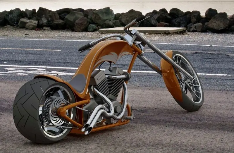
Now add appropriate scenes to the model.Here we are setting the white kitchen as the scene and Day time hdr as environment and we are not adding any special lights to the model because the scenes have their own lighting condetions which is suitable for our design
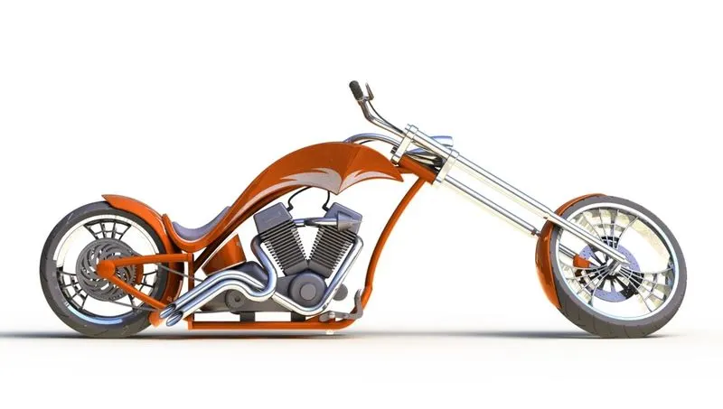
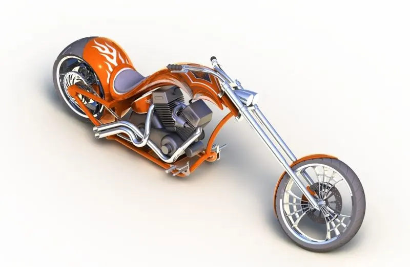
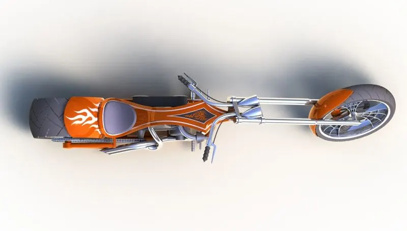
After setting up decals ,scene and camera take out the final render image in different views using photo view 360 and SOLIDWORK visualize
Final render images in different views are given below

CONCLUSION
- All the components are created with proper dimensional and geomatric constraints and I have made a better knowledge in part modeling
- Assembly of the american chopper has done succesfully and Learned almost every tools and features in SOLIDWORK assembly
- Hyper realistic images are rendered out and I have acquired immense knowledge in using SOLIDWORK photo view 360 and SOLIDWORK visualize