Surface Modelling and Rendering of SUNSEEKER PREDATOR YACHT
SURFACE MODELLING AND RENDERING OF SUNSEEKER PREDATOR YACHT
OBJECTIVE
The objectives of this project are to,
- Create all parts of the sunseeker yacht using solid and surface modelling in SOLIDWORKS
- Assemble all the parts with SOLIDWORKS assembly
- Create hyper realistic render images using SOLIDWORKS photo view 360 or SOLIDWORKS visualize
INTRODUCTION
Sunseeker international is a British luxury performance motor yacht brand,Originally named Poole Power Boats and the company changed its name to sunseeker international in 1985 .Here in this project ,we are creating ALL the parts of a sunseeker yacht named PREADATOR 108 and assembling it using SOLIDWORKS. There are five parts of the yacht which we are creating individually in this project which are propeller, radar ,hull ,radar mast and superstructure of the yacht.
The reason behind selecting this yacht as a design model is , this yacht has many smooth surfaces and complex shaped components which will help us to learn a lot in surface and solid modelling
We know every typical yacht will have a complex shape ,which is little harder to create its 3D model. Here the surface modelling scores. The complex shapes which are not achieved by solid modeling are achieved by surface modeling. So using surface features in the SOLIDWORKS all the complex shapes/parts expecially the hull and superstructure’ are modelled. In this project we are mostly dealing with surface modelling rather than the solid modeling .
Solid vs Surface Modelling
Solid modelling is for representing solid objects in the areas of CAD, engineering analysis, graphics and animation as well as prototyping and product visualization. It uses mathematical principles to create 3D solid objects.
The object is able to be seen in geographic terms, and is considered a “watertight” model because the internal details of the product are often included. Each part of the model is added one at a time until the complete model is finished. Assembly modelling can also play a part in solid modelling, which is simply when smaller parts of the model make up the whole.
Solid models can intersect, join and subtract objects from one another to create the desired results as far as shape and form.
Surface modelling focuses more on the external aspects of an object. It develops an object by stretching a surface over it with 3D curves created by the designer. It is essentially describing the surface boundaries of the object. It allows the viewer to see at each surface point where the solid interior is located.This type of modelling is used for creating the external aesthetics of a product or design. It can allow for more free-form shapes and it is considered sleeker by some. It lacks the “watertight” feature of solid modelling because if you were to cut into the design, it would be hollow. This gives solid modelling an advantage over surface modelling because the object can be defined more intricately, giving you a better idea of how the product or design will perform.
Another difference between solid and surface modelling is what they can do while you are developing a design. When developing designs using surface modelling, it can be hard to go back and make changes because they are not parametric. Making changes in one area may not create updates in the whole design. Solid models, on the other hand, are parametric, so you are able to look at the commands you used to create the design.
Each type of modelling serves its purpose depending on the type of design you are working on, so the pros and cons of each should be weighed to see which one will work for the design concept you have so that you can make the best use of their benefits.
DESIGN METHODOLOGY/APPROACH
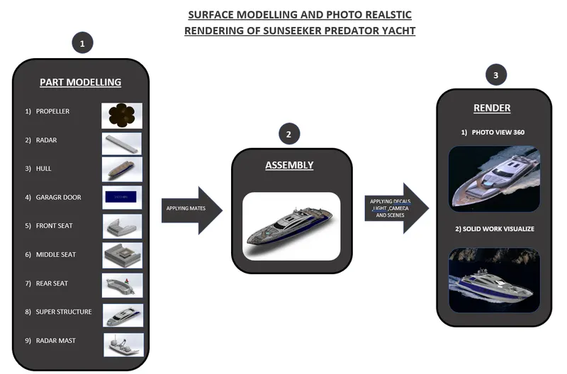
1) PART MODELLING
Part modelling is the process of creating individual 3D components(parts) from 2D sketches using SOLIDWORKS features. Parts are the building blocks of each SOLIDWORK model by which the assembly and render images are made.
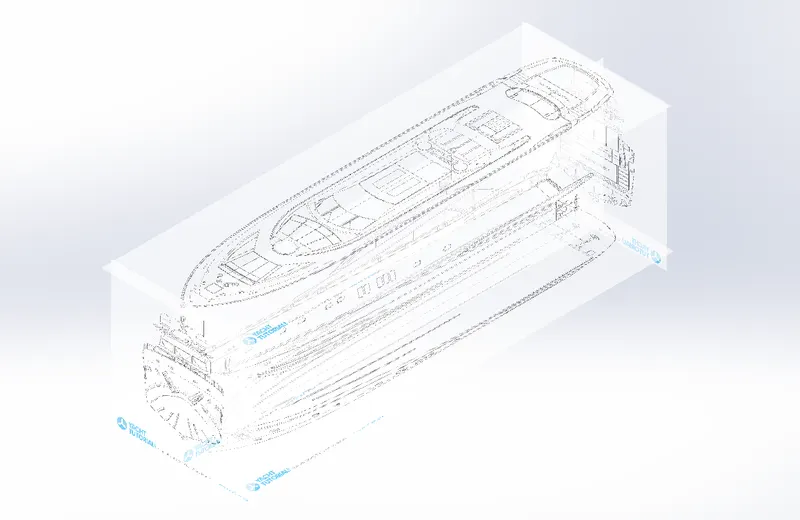
Blueprint set up: Before part modelling ,for easier creation of complex components such as hull, superstructure etc. we are taking the blueprints of the sunseeker yacht (front, back, side ,bottom and top) and making a Blueprint set up.
Here we are creating nine individual components which are the
- Propeller
- Radar
- Hull
- Garage Door
- Front Seat
- Middle Seat
- Rear Seat
- Superstructure
- Radar mast
All the parts that we are created must be saved in a safe folder with proper part names
PROPELLER
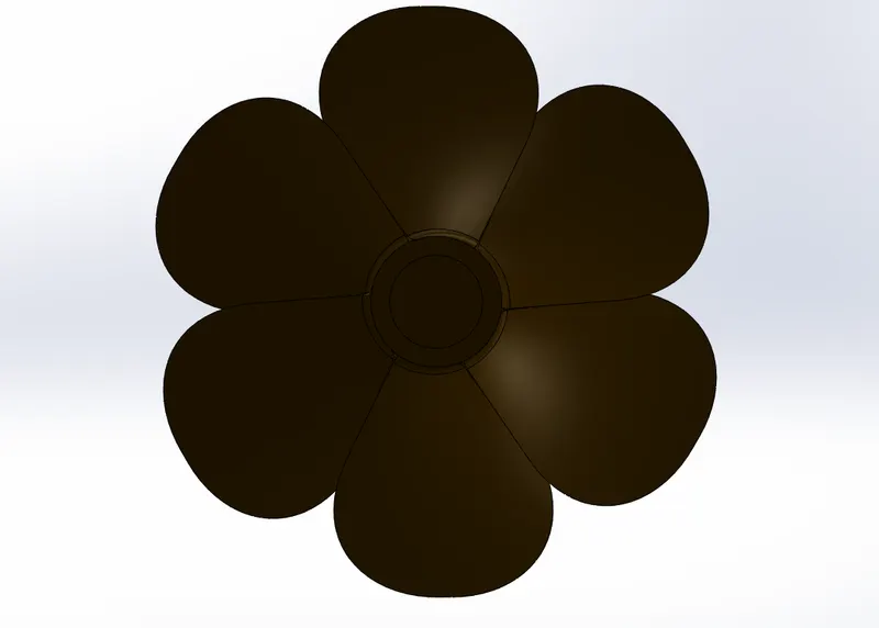
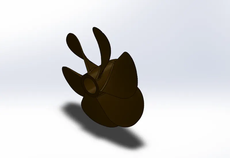
A propeller is a device with a rotating hub and radiating blades that are set at a pitch to form a helical spiral, that, when rotated, performs an action which is similar to Archimedes' screw. It transforms rotational power into linear thrust by acting upon a working fluid, such as water or air.
This is one of the easiest part of the yacht. Here the Hub of the propeller is created using the boss revolve of feature.Then leaves of the propeller are made by using a solu lift and adding fillets.
Tools used
- Line tool: Line tool is used to draw lines and arcs in the sketches.
- Smart dimensions: To add or edit dimensions of sketches.
- Arc : Arc tool is used to create arcs in the sketches .The three types of arcs in solid works are , 1) Three point arc , 2)Centrepoint arc , 3)tangent arc.
- Power Trim : it’s a handy tool to cut away sketch geometry quickly.
Features used
- Revolve boss/base : Revolve boss add material by revolving one or more profiles around an axis
- Fillet : Fillet is the feature used to create rounded internal or external faces in the edges of the parts
- Extruded Cut: This feature allows to easly remove material from a solid by extruding a profile along the normal to its plane
- Chamfer : The chamfer tool creates a beveled feature on selected edges, faces, or a vertex. ... Set the Distance and Angle in the Chamfer Property Manager or in the graphics area. A manipulator arrow appears that points in the direction in which the distance is measured.
- Appearance: Appearance is the option in solid works used to change the appearance of the 3D models. Appearance can be applied to a body or a single feature in that body
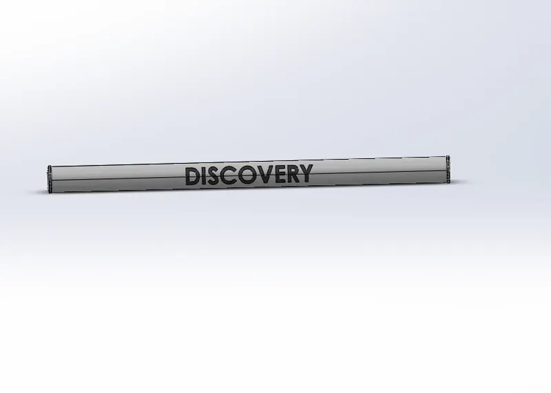
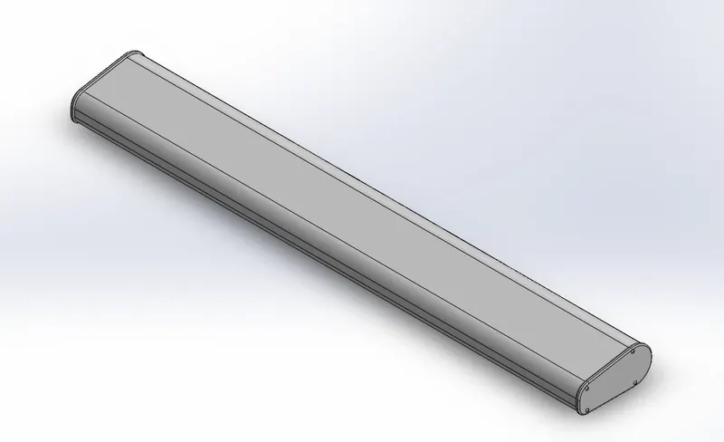
RADAR
Radars are the devices used to detect other ships and land obstacles, to provide bearing and distance for collision avoidance and navigation at sea. ... Radar is a vital navigation component for safety at sea and near the shore.
Tools used
- Line tool: Line tool is used to draw lines and arcs in the sketches.
- Smart dimensions: To add or edit dimensions of sketches.
- Arc : Arc tool is used to create arcs in the sketches .The three types of arcs in solid works are , 1) Three point arc , 2)Centrepoint arc , 3)tangent arc.
- Polygon : The entity used sketch polygonal shapes such as hexagon ,pentagon etc.
Features used
- Extruded Boss/Base: It is the feature which allows to take a 2D sketch and add thickness to it in the third dimension.
- Fillet : Fillet is the feature used to create rounded internal or external faces in the edges of the parts
- Extruded Cut: This feature allows to easly remove material from a solid by extruding a profile along the normal to its plane
- Mirror : Used to mirror a body or a feature about a plane or face
- Appearance: Appearance is the option in solid works used to change the appearance of the 3D models. Appearance can be applied to a body or a single feature in that body
HULL
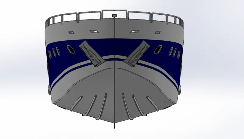
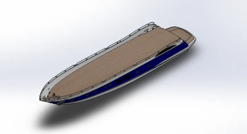
The hull of a yacht or a ship is the most notable structural entity of a ship/yacht. To define the hull, it can be said that it is the watertight enclosure of the ship/yacht , which protects the cargo, machinery, and accommodation spaces of the ship from the weather, flooding, and structural damage. In a yacht its super structure will be on the top of the hull.
The hull is the base structure of whole yacht and it is one of the complex part to model. Thus it is created by Surface modelling. after creating a surface body it is turned in to a solid body. After that create all other solid parts in the hull using features like boss extrude ,boss revolve etc.Using cut extrude option the space for the garage is cut out and saved as another part in-order to create the garage door
Tools used
- Line tool: Line tool is used to draw lines and arcs in the sketches
- Spline : Spline tool allow the user to create organic ,curvature continuous or complex curves.
- Arc : Arc tool is used to create arcs in the sketches .The three types of arcs in solid works are , 1) Three point arc , 2)Centrepoint arc , 3)tangent arc.
- Smart dimensions: To add or edit dimensions of sketches
- Circle : Tool used to draw circle sketches
- Slot entity: Used to create slot shapes on the sketches
- Convert entity : The Convert Entities tool allows users to make a copied projection of a given sketch, face, or set of edges onto the active sketch plane.
- Extent entities : It is used to extend entities to meet another sketch entity.
- Trim entities : Trim is used to trim/delete sketch entities
- Sketch fillet : Creates round corners instead of sharp corners
- Offset entities : The tool used create sketch offset
- Move/copy entities : This feature is used to move/copy a body or a geometry to one place to another pace
- Rectangle: It is used to make Rectangles in the sketch based on its center point ,corner etc.
Features used
- Reference planes: Reference planes are the planes created by taking face,edge ,other planes or curves as reference
- Projected curve : A projected cure is the projection of two curves, Ie it is the intersection of the surface created by two curves
- Loafted Surface : The loft feature is an important tool for (surface) modelling in SolidWorks. The loft feature creates a shape by making transitions between multiple profiles and guide curves. This tool is very valuable for modelling complex surfaces.
- Trim Surface : Feature used to remove unwanted surfaces from the models
- Extrude surface: Using Extrude surface feature ,we can extrude the edges of a solid body , surface body or a sketch to a customized direction.
- Swept Surface : It if a surface feature used to generate surfaces using section curves positioned along a path
- Knit surface : Feature used to combine two or more surfaces in to one
- Swept cut : Swept cut is a feature to remove materials of a body along a sweep path
- Shell : The shell tool hollows out a part, leaves open the faces you select, and creates thin-walled features on the remaining faces. If we do not select any face on the model, we can shell a solid part, creating a closed, hollow model. We can also shell a model using multiple thicknesses
- Fillet : Fillet is the feature used to create rounded internal or external faces in the edges of the parts
- Extruded Boss/Base: It is the feature which allows to take a 2D sketch and add thickness to it in the third dimension
- Revolve boss/base : Revolve boss add material by revolving one or more profiles around an axis
- Sweep Boss/Base : Within SOLIDWORKS, a sweep is a tool that creates a solid, a cut or a surface feature by moving a profile along a path. To create a solid, use the Swept Boss tool to move a profile along a path. The profile can contain one or more closed contours.
- Extruded Cut: This feature allows to easly remove material from a solid by extruding a profile along the normal to its plane
- Mirror : Used to mirror a body or a feature about a plane
- Linear Pattern : The option used to create a pattern of feature or body along a linear reference
- Split line : It is the feature used to separate a single surface(curved or planar) to multiple by projecting the sketch over it
- Chamfer : The chamfer tool creates a beveled feature on selected edges, faces, or a vertex. ... Set the Distance and Angle in the Chamfer Property Manager or in the graphics area. A manipulator arrow appears that points in the direction in which the distance is measured.
- Appearance: Appearance is the option in solid works used to change the appearance of the 3D models. Appearance can be applied to a body or a single feature in that body
GARAGE DOOR
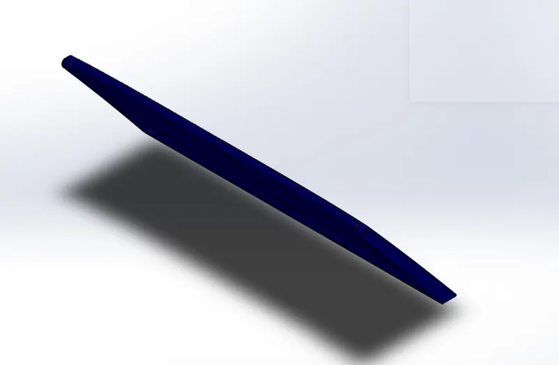
The garage in a yacht is the space which is used keep the vehicles such as a car ,bike etc. inside the yacht. The door of this garage is called garage door and it is modelled as an individual component in this project
Garage door is created by Extrude cutting the garage space away from the hull and saving it as a separate part. This part again reduced its thickness by extrude cutting , applying appropriate fillets and mirroring it to get the complete garage door

Tools used
- Line tool: Line tool is used to draw lines and arcs in the sketches
- Spline : Spline tool allow the user to create organic ,curvature continuous or complex curves.
- Arc : Arc tool is used to create arcs in the sketches .The three types of arcs in solid works are , 1) Three point arc , 2)Centrepoint arc , 3)tangent arc.
- Smart dimensions: To add or edit dimensions of sketches.
Features used
- Extruded Boss/Base: It is the feature which allows to take a 2D sketch and add thickness to it in the third dimension
- Extruded Cut: This feature allows to easly remove material from a solid by extruding a profile along the normal to its plane
- Mirror : Used to mirror a body or a feature about a plane
- Appearance: Appearance is the option in solid works used to change the appearance of the 3D models. Appearance can be applied to a body or a single feature in that body
- Fillet : Fillet is the feature used to create rounded internal or external faces in the edges of the parts
FRONT SEAT
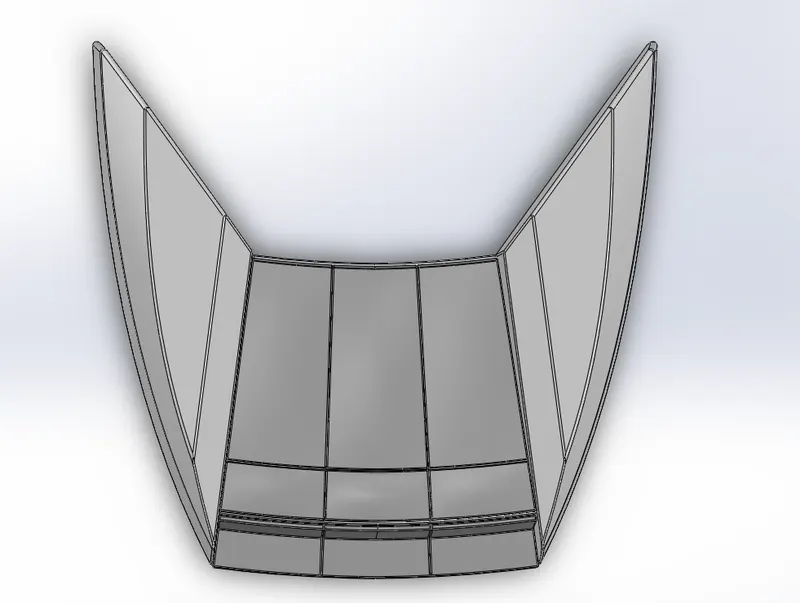
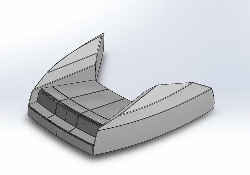
The seat in the font side of the yacht is also modelled as a single individual component.
For creating the middle seat the deck surface is taken from the hull as the reference and sketches in appropriate planes are extruded and apply specific features in-order to get the desired shape of the seat. Apart from 2D sketch 3D sketches are also used in making of the front seat
Tools used
- Line tool: Line tool is used to draw lines and arcs in the sketches
- Spline : Spline tool allow the user to create organic ,curvature continuous or complex curves.
- Arc : Arc tool is used to create arcs in the sketches .The three types of arcs in solid works are , 1) Three point arc , 2)Centrepoint arc , 3)tangent arc.
- Smart dimensions: To add or edit dimensions of sketches.
- Circle : Tool used to draw circle sketches
- Rectangle: It is used to make Rectangles in the sketch based on its center point ,corner etc.
Features used
- Reference planes: Reference planes are the planes created by taking face,edge ,other planes or curves as reference
- Projected curve : A projected cure is the projection of two curves ,ie it is the intersection of the surface created by two curves
- Loafted Surface : The loft feature is an important tool for (surface) modelling in SolidWorks. The loft feature creates a shape by making transitions between multiple profiles and guide curves. This tool is very valuable for modelling complex surfaces.
- Trim Surface : Feature used to remove unwanted surfaces from the models
- Extrude surface: Using Extrude surface feature ,we can extrude the edges of a solid body , surface body or a sketch to a customized direction.
- Knit surface : Feature used to combine two or more surfaces in to one
- Fillet : Fillet is the feature used to create rounded internal or external faces in the edges of the parts
- Extruded Boss/Base: It is the feature which allows to take a 2D sketch and add thickness to it in the third dimension
- Extruded Cut: This feature allows to easly remove material from a solid by extruding a profile along the normal to its plane
- Mirror : Used to mirror a body or a feature about a plane
- Dome: The feature used to create dome shapes in the surfaces
- Appearance: Appearance is the option in solid works used to change the appearance of the 3D models. Appearance can be applied to a body or a single feature in that body
MIDDLE SEAT
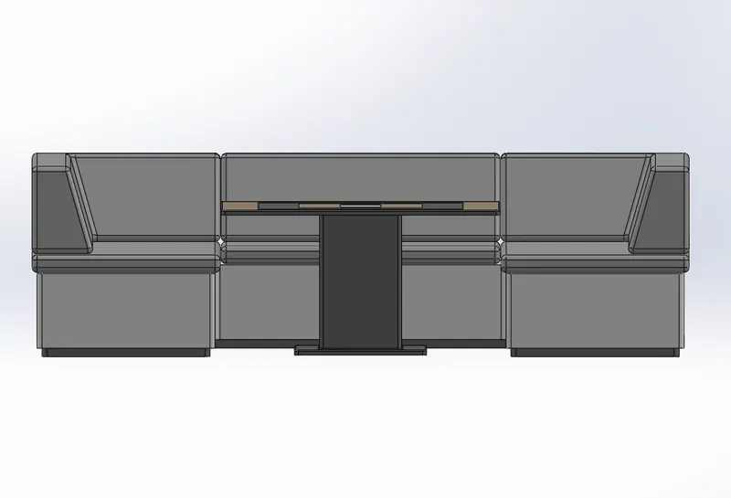
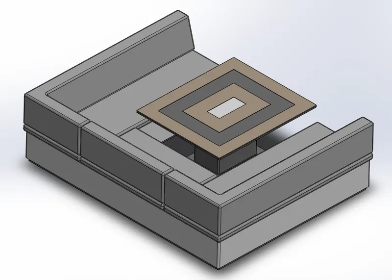
Middle seat is the seat in between the rear seat and front seat which is located just behind the super structure. Middle seat is a structure with a small table surrounded its three sides with the seates.
Methodology of creating middle seat is almost same as the front seat. Like front seat middle seat also created by taking the deck surface as the reference.
Tools used
- Line tool: Line tool is used to draw lines and arcs in the sketches
- Spline : Spline tool allow the user to create organic ,curvature continuous or complex curves.
- Arc : Arc tool is used to create arcs in the sketches .The three types of arcs in solid works are , 1) Three point arc , 2)Centrepoint arc , 3)tangent arc.
- Smart dimensions: To add or edit dimensions of sketches.
- Circle : Tool used to draw circle sketches
- Rectangle: It is used to make Rectangles in the sketch based on its center point ,corner etc.
Features used
- Reference planes: Reference planes are the planes created by taking face,edge ,other planes or curves as reference
- Projected curve : A projected cure is the projection of two curves, ie it is the intersection of the surface created by two curves
- Loafted Surface : The loft feature is an important tool for (surface) modelling in SolidWorks. The loft feature creates a shape by making transitions between multiple profiles and guide curves. This tool is very valuable for modelling complex surfaces.
- Trim Surface : Feature used to remove unwanted surfaces from the models
- Extrude surface: Using Extrude surface feature ,we can extrude the edges of a solid body , surface body or a sketch to a customized direction.
- Knit surface : Feature used to combine two or more surfaces in to one
- Fillet : Fillet is the feature used to create rounded internal or external faces in the edges of the parts
- Extruded Boss/Base: It is the feature which allows to take a 2D sketch and add thickness to it in the third dimension
- Extruded Cut: This feature allows to easly remove material from a solid by extruding a profile along the normal to its plane
- Mirror : Used to mirror a body or a feature about a plane
REAR SEAT
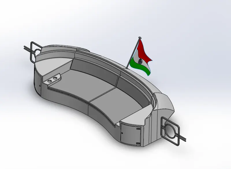
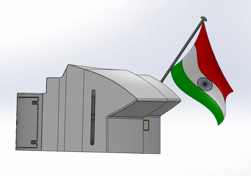
The seat at the back end of the deck surface is the rear seat.
Tools used
- Line tool: Line tool is used to draw lines and arcs in the sketches
- Spline : Spline tool allow the user to create organic ,curvature continuous or complex curves.
- Arc : Arc tool is used to create arcs in the sketches .The three types of arcs in solid works are , 1) Three point arc , 2)Centrepoint arc , 3)tangent arc.
- Smart dimensions: To add or edit dimensions of sketches.
- Circle : Tool used to draw circle sketches
- Rectangle: It is used to make Rectangles in the sketch based on its center point ,corner etc.
Features used
- Projected curve : A projected cure is the projection of two curves, ie it is the intersection of the surface created by two curves
- Loafted Surface : The loft feature is an important tool for (surface) modelling in SolidWorks. The loft feature creates a shape by making transitions between multiple profiles and guide curves. This tool is very valuable for modelling complex surfaces.
- Trim Surface : Feature used to remove unwanted surfaces from the models
- Extrude surface: Using Extrude surface feature ,we can extrude the edges of a solid body , surface body or a sketch to a customized direction.
- Knit surface : Feature used to combine two or more surfaces in to one
- Fillet : Fillet is the feature used to create rounded internal or external faces in the edges of the parts
- Extruded Boss/Base: It is the feature which allows to take a 2D sketch and add thickness to it in the third dimension
- Extruded Cut: This feature allows to easly remove material from a solid by extruding a profile along the normal to its plane
- Mirror : Used to mirror a body or a feature about a plane
- Combine : The option to add two or more bodies together
- Appearance: Appearance is the option in solid works used to change the appearance of the 3D models .Appearance can be applied to a body or a single feature in that body
RADAR MAST
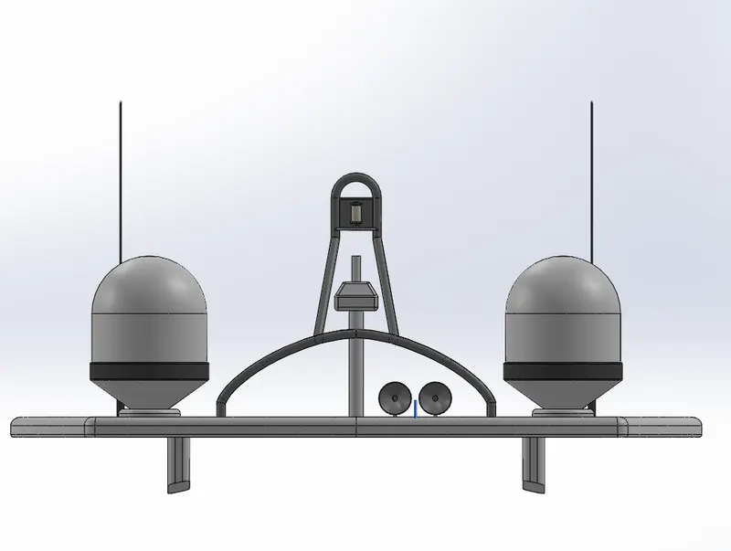
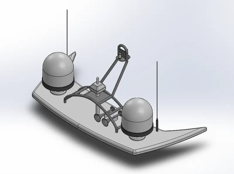
Radar mast is the structure above the superstructure which holds (supporting structure) the radar. It consist of holding structure of radar , 2 antinas ,railimgs etc.Its created using one surface of the super structure and the blueprint as reference.
Tools used
- Line tool: Line tool is used to draw lines and arcs in the sketches
- Spline : Spline tool allow the user to create organic ,curvature continuous or complex curves.
- Arc : Arc tool is used to create arcs in the sketches .The three types of arcs in solid works are , 1) Three point arc , 2)Centrepoint arc , 3)tangent arc.
- Smart dimensions: To add or edit dimensions of sketches.
- Circle : Tool used to draw circle sketches
- Rectangle: It is used to make Rectangles in the sketch based on its center point ,corner etc.
Features used
- Extruded Boss/Base: It is the feature which allows to take a 2D sketch and add thickness to it in the third dimension
- Shell : The shell tool hollows out a part, leaves open the faces you select, and creates thin-walled features on the remaining faces. If we do not select any face on the model, we can shell a solid part, creating a closed, hollow model. We can also shell a model using multiple thicknesses
- Revolve boss/base : Revolve boss add material by revolving one or more profiles around an axis
- Sweep Boss/Base : Within SOLIDWORKS, a sweep is a tool that creates a solid, a cut or a surface feature by moving a profile along a path. To create a solid, use the Swept Boss tool to move a profile along a path. The profile can contain one or more closed contours.
- Dome: The feature used to create dome shapes in the surfaces
- Mirror : Used to mirror a body or a feature about a plane or face
- Fillet : Fillet is the feature used to create rounded internal or external faces in the edges of the parts
SUPERSTRUCTURE
A superstructure is an extended construction of any building or platform that rises above the rest of the building or platform in a distinct manner. ... Thus, superstructure means to add a construction to an already existing structure. In ships this is the name given to the part of the ship that emerges from the deck.
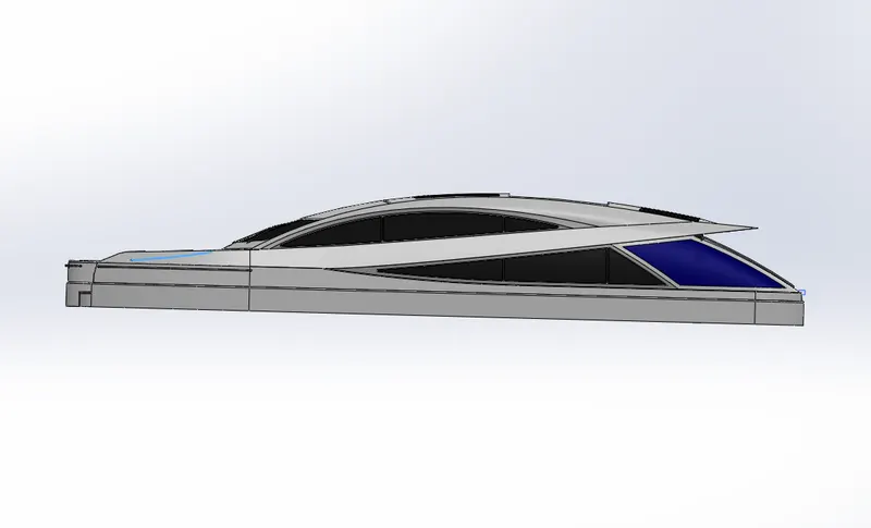
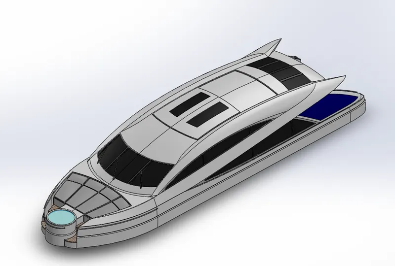
The superstructure is the most complex part that we are modelling. Here apart from solid modelling ,surface modelling is used to create the superstructure .Both 2D and 3D sketches are used in this part modelling. Different projected curves are created using different sketches and its is used to loft or fill surfaces .Finally the surface body is converted to a solid body and giving the proper appearance .
Tools used
- Line tool: Line tool is used to draw lines and arcs in the sketches
- Spline : Spline tool allow the user to create organic ,curvature continuous or complex curves.
- Arc : Arc tool is used to create arcs in the sketches .The three types of arcs in solid works are , 1) Three point arc , 2)Centrepoint arc , 3)tangent arc.
- Smart dimensions: To add or edit dimensions of sketches
- Circle : Tool used to draw circle sketches
- Convert entity : The Convert Entities tool allows users to make a copied projection of a given sketch, face, or set of edges onto the active sketch plane.
- Extent entities : It is used to extend entities to meet another sketch entity.
- Trim entities : Trim is used to trim/delete sketch entities
- Sketch fillet : Creates round corners instead of sharp corners
- Offset entities : The tool used create sketch offset
- Move/copy entities : This feature is used to move/copy a body or a geometry to one place to another pace
- Rectangle: It is used to make Rectangles in the sketch based on its center point ,corner etc.
Features used
- Reference planes: Reference planes are the planes created by taking face,edge ,other planes or curves as reference
- Projected curve : A projected cure is the projection of two curves, Ie it is the intersection of the surface created by two curves
- Loafted Surface : The loft feature is an important tool for (surface) modelling in SolidWorks. The loft feature creates a shape by making transitions between multiple profiles and guide curves. This tool is very valuable for modelling complex surfaces.
- Trim Surface : Feature used to remove unwanted surfaces from the models
- Extrude surface: Using Extrude surface feature ,we can extrude the edges of a solid body , surface body or a sketch to a customized direction.
- Swept Surface : It if a surface feature used to generate surfaces using section curves positioned along a path
- Knit surface : Feature used to combine two or more surfaces in to one
- Swept cut : Swept cut is a feature to remove materials of a body along a sweep path
- Shell : The shell tool hollows out a part, leaves open the faces you select, and creates thin-walled features on the remaining faces. If we do not select any face on the model, we can shell a solid part, creating a closed, hollow model. We can also shell a model using multiple thicknesses
- Fillet : Fillet is the feature used to create rounded internal or external faces in the edges of the parts
- Extruded Boss/Base: It is the feature which allows to take a 2D sketch and add thickness to it in the third dimension
- Revolve boss/base : Revolve boss add material by revolving one or more profiles around an axis
- Sweep Boss/Base : Within SOLIDWORKS, a sweep is a tool that creates a solid, a cut or a surface feature by moving a profile along a path. To create a solid, use the Swept Boss tool to move a profil along a path. The profile can contain one or more closed contours.
- Extruded Cut: This feature allows to easly remove material from a solid by extruding a profile along the normal to its plane
- Mirror : Used to mirror a body or a feature about a plane
- Linear Pattern : The option used to create a pattern of feature or body along a linear reference
- Split line : It is the feature used to separate a single surface(curved or planar) to multiple by projecting the sketch over it
- Chamfer : The chamfer tool creates a beveled feature on selected edges, faces, or a vertex. ... Set the Distance and Angle in the Chamfer Property Manager or in the graphics area. A manipulator arrow appears that points in the direction in which the distance is measured.
- Appearance: Appearance is the option in solid works used to change the appearance of the 3D models. Appearance can be applied to a body or a single feature in that body
ASSEMBLY OF SUNSEEKER PREDATOR YACHT
Assembly is one of the main feature of SOLIDWORK which allows us to assemble the individual parts using an option called assembly mates
Assembly mates are the geometric relations (such as coincident ,concentric ,parallel etc.) applied between different parts while assembling them. In solid work three types of mates than we can use. They are
- Standard mate : They are the common geometric relations such as concentric , coincident ,parallel etc.
- Advanced mate : This option allows us to decide the distance between the components ,angle between the components etc.
- Mechanical mate : To make things simpler, SOLIDWORKS has a set of mates, called mechanical mates, that can be used to mimic real-world interaction that might be difficult to simulate with just the standard mates. We can use mechanical mates for components such as cams, gears, and universal joints.
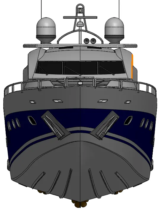
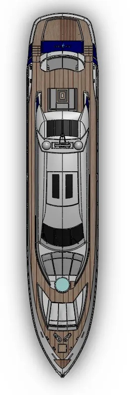
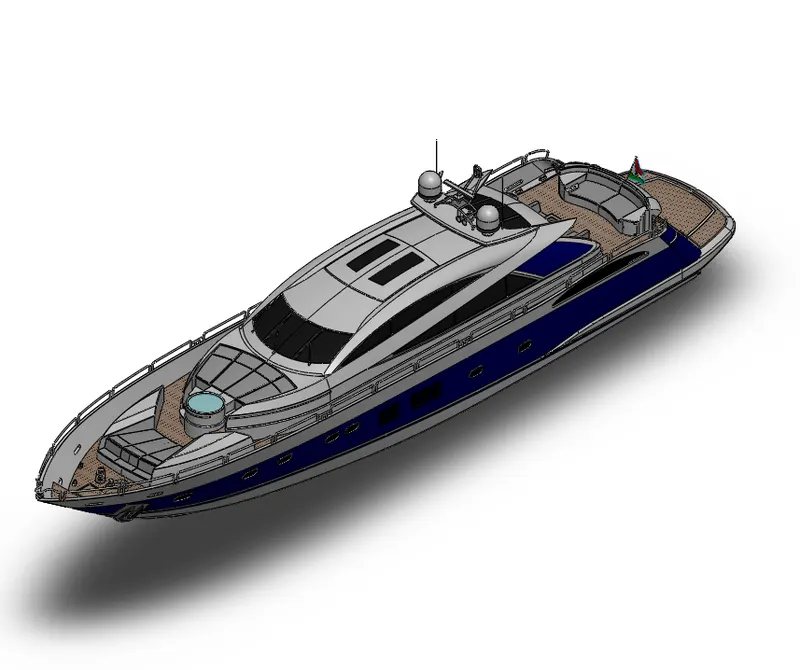
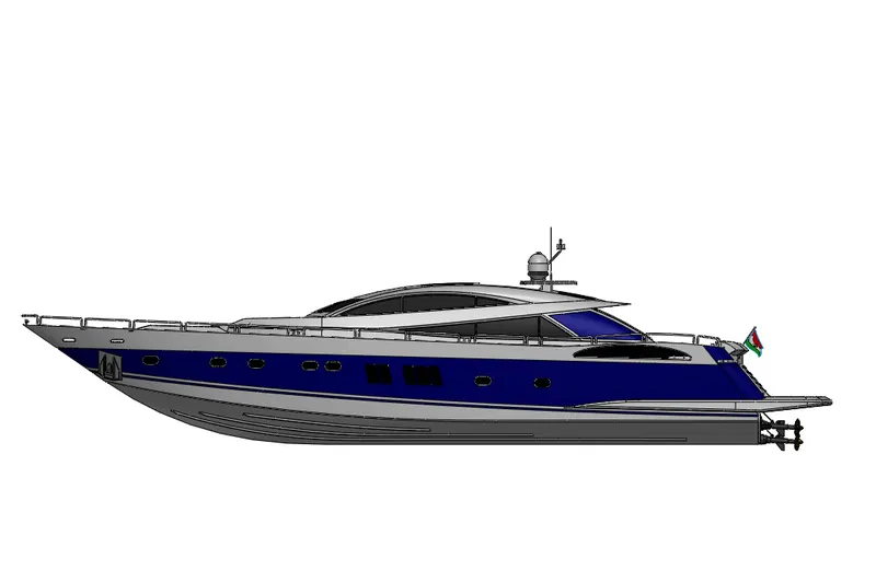
Here we are assembling the all the individual components of sunseeker predator yacht using SOLIDWORKS assembly by applying proper mates
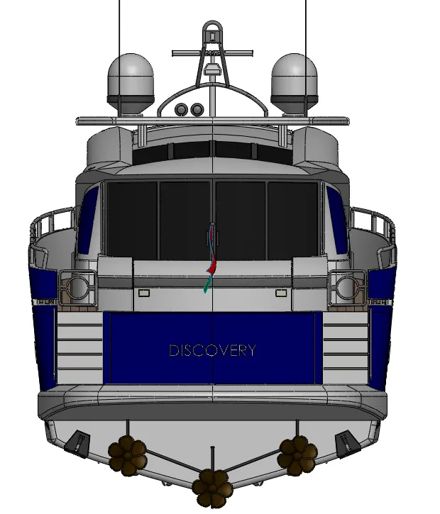
For that first of all we need to create a new assembly document in solid works .Now import the hull as the first component and it will automatically fix in the proper planes .Then import all other components one by one .
Here we have taken the deck surface as reference in modelling some parts such as superstructure,radar mast etc.Thus we need not to apply any mates to those part ,it will automatically fixes in the hull. Apply proper mates to the parts which are not created by taking a reference surface and save the assembly in the name SUNSEEKER PREDATOR YACHT
View Model : https://drive.google.com/file/d/1YFtYOsKwc99hQEUh3jlx58_NhkFTFFV8/view?usp=sharing
RENDERING OF SUNSEEKER PREDATOR YACHT
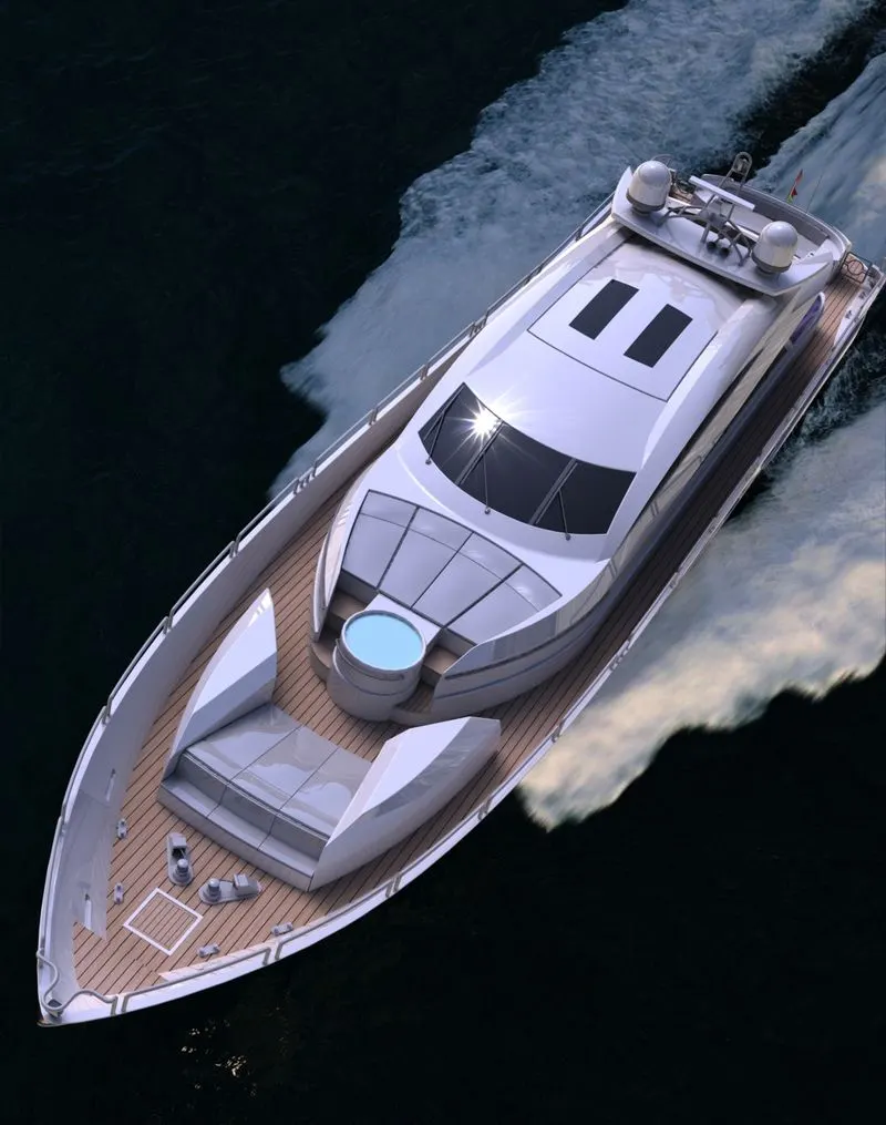
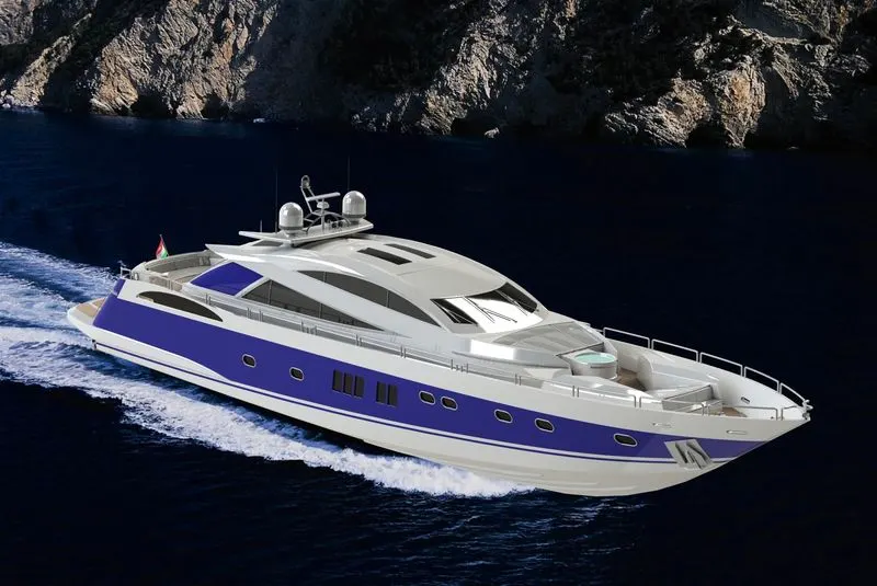
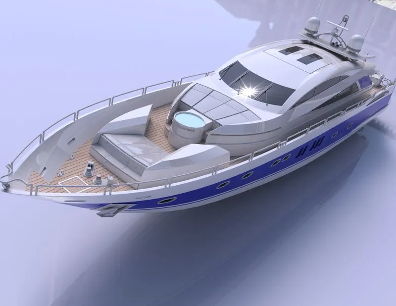
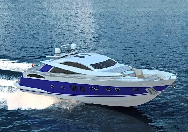
Rendering is the process of creating HyperRealistic images of the components/assembly.Here we are using SOLIWORK add-ins such as SOLIWORK Photo view 360 and SOLIDWORK Visualize to render our assembly.
PhotoView 360 : PhotoView 360 is a SOLIDWORKS add-in that produces photo-realistic renderings of SOLIDWORKS models. The rendered image incorporates the appearances, lighting, scene, and decals included with the model.
SOLIDWORKS Visualize : SOLIDWORKS Visualize allows us to leverage our 3D CAD data to create photo-quality content in the fastest and easiest way we can–from images to animations, interactive web content, and immersive Virtual Reality. ... SOLIDWORKS Visualize is the “camera” for our CAD data!
Before the final render we have the options such as adding’
- Decals : Decals are the graphics that we can wrap on a solid body.For eg. Adding stickers to the fuel tank etc.
- Camera : Using camera option we can set up a camera view and save that view.
- Scene : The option to set up a sene,environment and background.
- Lights : Using light option we can add lights to the model.Types of lights in SOLIDWORKS are 1) Directional light 2)Point light 3) Spot light 4) Sunlight
After applying proper decals , lights , camera , and scene click on the fienal render option to get the realistic rendered images
CONCLUSION
- All the components are created with proper dimensional and geometric constraints and I have made a better knowledge in Surface Modelling as well as Solid Modelling
- Assembly of the SUNSEEKER PREDATOR YACHT has done successfully .
- Hyper realistic images are rendered out and I acquired immense knowledge in using SOLIDWORK photo view 360 and SOLIDWORK visualize
View Model : https://drive.google.com/file/d/1YFtYOsKwc99hQEUh3jlx58_NhkFTFFV8/view?usp=sharing