Photo Realistic Rendering
Modeling and Rendering an American Chopper in Solidworks
Objective
- The Main objective is to create different parts of American chopper in Solidworks.
- Assembly of modeled parts pf chopper in Solidworks.
- Rendering of Assembled chopper in PhotoView360. In addition, setting up cameras, Decals, and lights.
Methodology
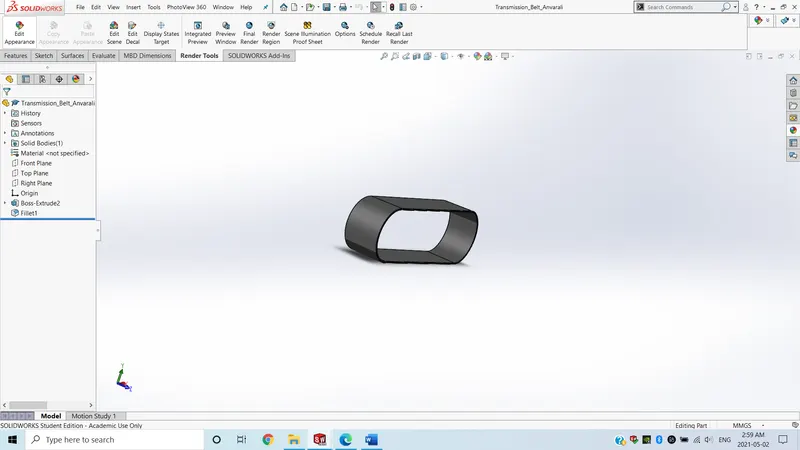
Transmission Belt
- A component, which is used to transmit power from engine to rear wheel.
- A 2D sketch was created in Solidworks 2D environment with specified dimensions and offset of whole surface was given.
- Extrude boss feature was used to convert sketch to 3D model with a given dimension. A matte rubber appearance is applied to belt to create realistic model.
Kick Stand
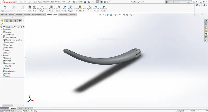
- It is used to support chopper when it stands on ground.
- A lofted Boss feature was used to interpolate a model between two different cross section sketches which is followed by dome feature to create smooth shape on end profiles.
- A cut extrude was used to subtract a solid portion from a solid body followed by fillet to smooth external edges.
Front Fender
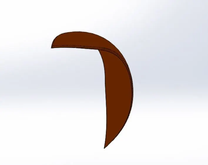
- A sketch was created using sketch option using appropriate relations.
- Mainly, A spline tool was used to draw a curve through interpolation points which was followed by a revolve boss to create a solid model from 2D sketch with a reference.
Rear Fender
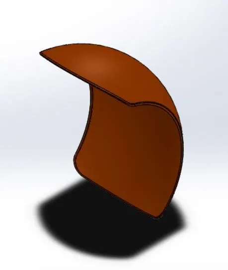
- The same features with same methodology but different dimensions were used to make a solid rear fender as they were used in front fender.
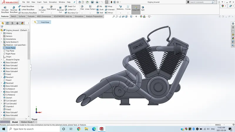
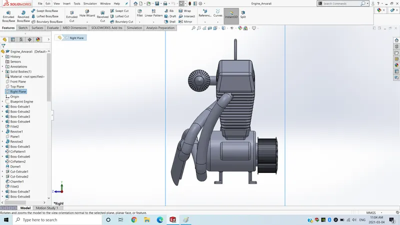
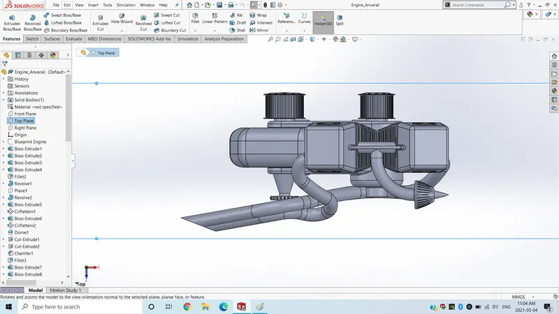
Engine
- A blueprint sketch was inserted through sketch picture for reference.
- Line, Circle, Arc, Spline, convert entities and intersection curves were used to create sketch with appropriate dimensions and relations.
- Boss sweep was used to create a solid body along the profile curve as well as boss extrude was used to make a solid body from 2D sketch.
- Boss-Revolve is used to revolve 2D sketch around a reference to make a solid body.
- Cut-Extrude was used to subtract solid portion from the body.
- Mirror tool was used to mirror feature as well as sketch with reference.
- Reference plane was created to construct more reference.
- Combine feature was used to merge solid bodies.
- Composite curves were used to create a curve from two or more curves.
- Circular pattern was used to make a pattern of feature or body along with circular reference.
- Linear pattern was used to pattern feature or body along with linear reference.
- Chamfer was used to convert sharp edges into bevel edges.
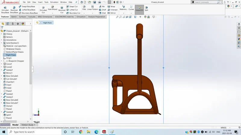
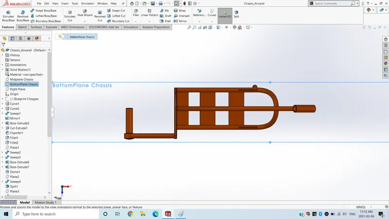
Chasse
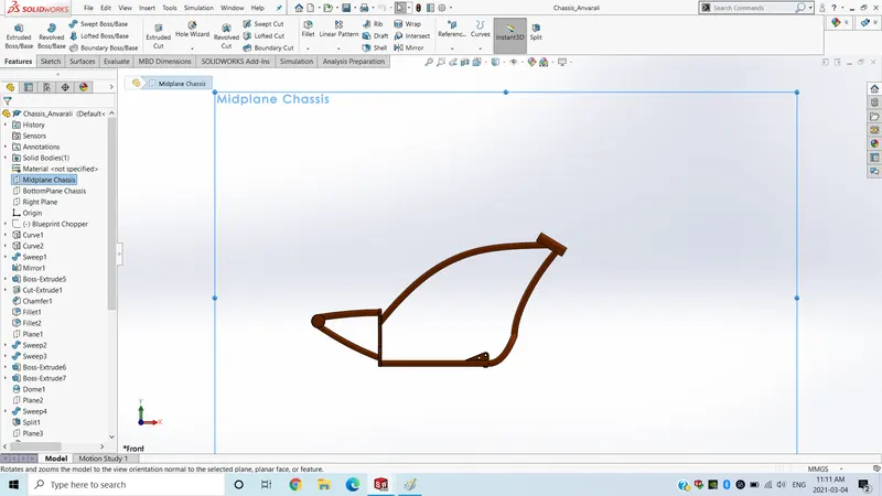
- A blueprint sketch was inserted through sketch picture for reference.
- Line, Circle, Arc, Spline, convert entities and intersection curves were used to create sketch with appropriate dimensions and relations.
- Boss sweep was used to create a solid body along the profile curve as well as boss extrude was used to make a solid body from 2D sketch.
- Cut-Extrude was used to subtract solid portion from the body.
- Boss Extrude was used to create a solid body from 2D sketch.
- Mirror tool was used to mirror feature as well as sketch with reference.
- Reference plane was created to construct more reference.
- Combine feature was used to merge solid bodies.
- Composite curves were used to create a curve from two or more curves.
- Chamfer was used to convert sharp edges into bevel edges.
Gas Tank
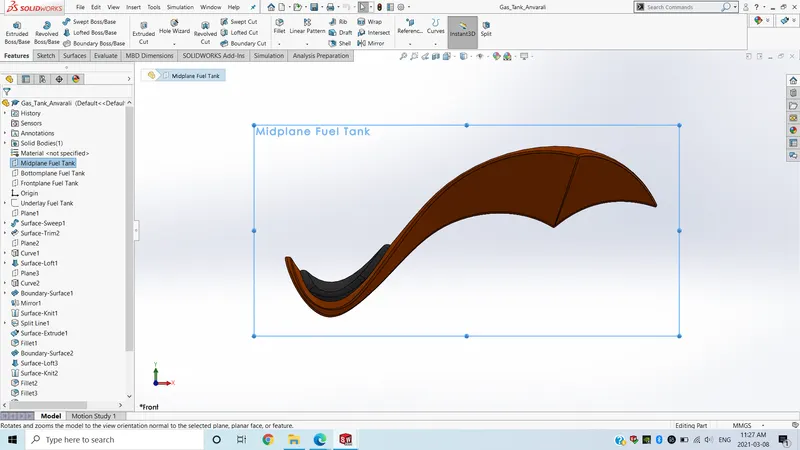
- A blueprint sketch was inserted through sketch picture for reference.
- Line was used to draw lines and construction lines.
- Spline was used to draw a curve through interpolation points.
- Boss Extrude was used to create a solid body from 2D sketch.
- Reference plane was created to construct more reference.
- Surface-loft was used to create surface along the profile.
- Knit-surface tool was used to combine adjacent non-intersecting features.
- Boundary-surface was used to create a boundary from the closed profile.
- Surface sweep was used to create a sweep profile along the sketch.
- Shell feature was used to convert solid bodies to shells.
Front Fork
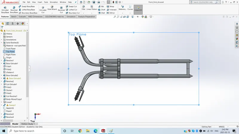
- Line, Circle, Arc, Spline, convert entities and intersection curves were used to create sketch with appropriate dimensions and relations.
- Boss sweep was used to create a solid body along the profile curve as well as boss extrude was used to make a solid body from 2D sketch.
- Boss-Revolve is used to revolve 2D sketch around a reference to make a solid body.
- Cut-Extrude was used to subtract solid portion from the body.
- Reference plane was created to construct more reference.
- Mirror tool was used to mirror feature as well as sketch with reference.
- Combine feature was used to merge solid bodies.
- Linear pattern was used to pattern feature or body along with linear reference.
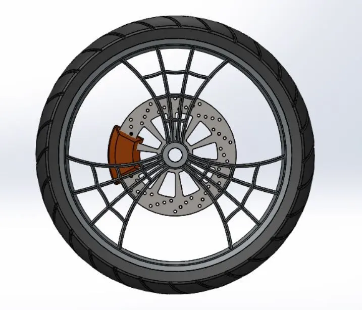
Front Wheel
- Line, Circle, Arc, Spline, convert entities and intersection curves were used to create sketch with appropriate dimensions and relations.
- Offset entities were used to offset or duplicate existing lines.
- Boss Extrude was used to create a solid body from 2D sketch.
- Boss-Revolve is used to revolve 2D sketch around a reference to make a solid body.
- Cut-Extrude was used to subtract solid portion from the body.
- Cut-revolve was used to subtract solid portion from solid body using 2D sketch revolve.
- Combine feature was used to merge solid bodies.
- Chamfer was used to convert sharp edges into bevel edges.
- Circular pattern was used to make a pattern of feature or body along with circular reference.
- Linear pattern was used to pattern feature or body along with linear reference.
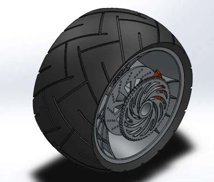
Rear Wheel
- The same features with same methodology but different dimensions were used to make a solid rear fender as they were used in front fender.
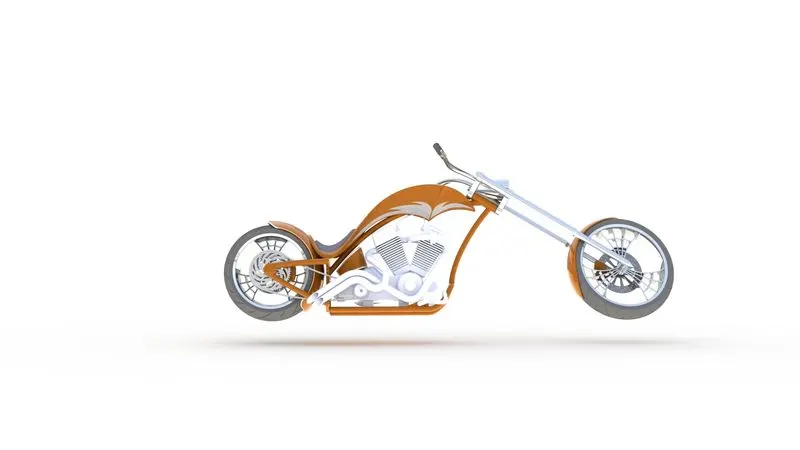
Assembly & Rendering of Chopper
- Mattes were used to create constraints between surfaces.
- Decals were used to insert graphics on chopper bodies.
- Light & Camera were used to adjust camera and lighting.
- Render feature was used to rendered chopper with quality and size.
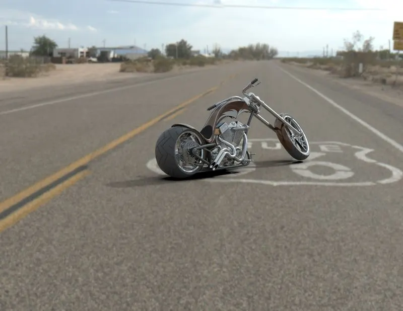
- Solidworks Visualize was used to rendered chopper in environment.
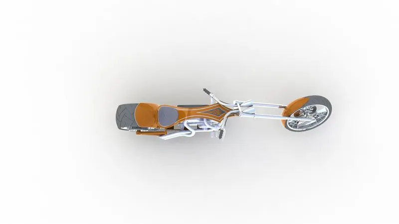
Front View
Top View
Rear View
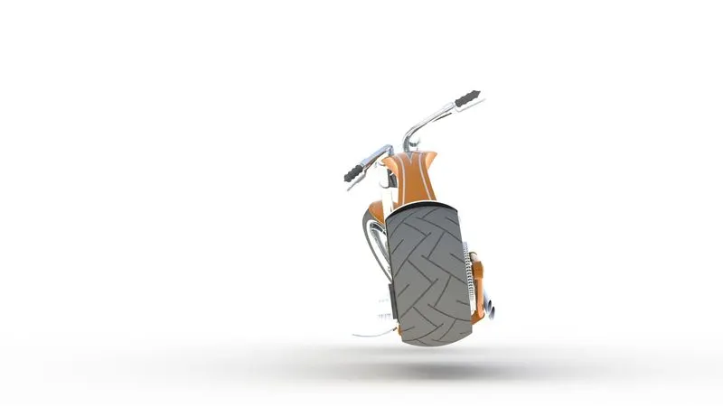
Camera View
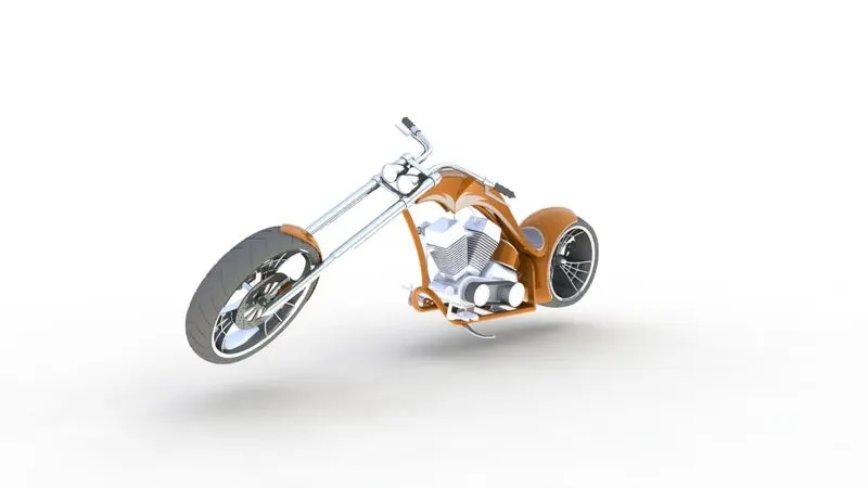
Rendered with Environment.
Conclusion
- Hence, Chopper parts were modelled and assembled in Solidworks assembly environments.
- A realistic image of chopper was created using Photoview360 and solidworks Visualize.