Photo Realistic Rendering
Report on Assembly of Chopper Model:
Objective:
The main objective of the project is to create a photo-realistic conceptual model of an American Chopper using solid work. By creating part drawings, converting them into 3d models, assembling the created parts, and finally giving it a photo-realistic view by rendering the model; using photo view-360.
Introduction:
Solidworks is a 3D Modelling Computer-Aided Design (CAD) and simulation-based software. To create a 3D model, it used the parametric future-based approach (Developed by PTC) by taking the input from the user.
Chopper :
A Chopper is a type of custom motorcycle that emerged in California in the late 1950s. The chopper is perhaps the most extreme of all custom styles, often using radically modified steering angles and lengthened forks for a stretched-out appearance. They can be built from an original motorcycle which is modified or built from scratch. Some of the characteristic features of the chopper are long front ends with extended forks coupled with increased rank angles, hardtail frames (frames without rear suspension), very tall "ape hanger" or very short drag handlebars, lengthened or stretched frames, and larger than the stock front wheel.
Design Methodology:
Visualization is the Key
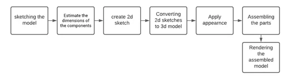
Modeling:
American Chopper consists of :
Front Fender
Chassis
Rear Fender
Front Firk
Gas Tank
Oil Tank
Front Wheel
Side Stand
Rear Wheel
Engine
The major Tools/Features used in the solid works for modeling the chopper were:
1, Creating a 2D sketch:
A 2D sketch is a base to create a 3D model. It is usually created on the X-axis & -axis. This includes lines, circles, rectangles, spline, etc.
The status of a Sketch: The current status of the sketch is displayed in the lower right corner of the screen
Fully Defines in Black, Under Defined in Blue, and Over Defined in Red
2, Geometric Relation:
It is one of the most powerful relations in Solidworks.
They are used at the sketch level to control the behavior of the sketch entities when they are moved or rotate and to associations between one another.
3, Solid Extrude:
It extrudes a sketch or selected sketch contours in one or two directions to create a solid feature
Create a sketch. You can use a closed profile sketch or an open profile sketch. For cuts, open profile sketches are only valid for Blind or Through All end condition.
Click one of the extrudes tools Insert >Bose/Base>Extrude.
Click OK.
4, Extrude Cut:
Extrude cut is a feature that helps to remove materials from the 3D model. It is just opposite to extrude boss/base feature because it cuts a sketch profile while extruding. It can cut in both directions and mainly used for creating, holes, channels, and slots.
Sketch on a plane and/or planer surface.
The sketch should be closed and define.
Then select the cut to extrude command, to cut the solid.
5, Revolve Boss:
Revolve a sketch or select a sketch contours around an axis to create a solid feature.
Create a new 2D sketch.
Create all solid sketch geometry on one side of the axis.
Choose to revolve Bose/Base from the feature menu.
Pick the axis you wish to use to revolve
Specific direction and angle
Accept the Feature
6, Revolve Cut:
Cuts a solid model by revolving a solid profile around an axis.
7, Swept Boss:
This feature sweeps a closed profile and an open or closed path to create a solid path.
Create a line or spline sketch.
Select the profile need to extrude
Select the path with extruding needs to be done
8, Loft:
The loft feature creates a shape by making the transition between multiple profiles and guide curves thus allowing the creation of complex geometry with a single tool. This can be used in both solid and surface modeling.
9, Dome:
A dome is a rounded vault forming the outside face of a body or a structure, typically with a circular base.
Click Dome on the feature toolbar or click insert > feature > Dome.
Select one or more planer or non-planar faces. Set a value for the distance by which the dome expands.
Click create to the concave dome.
10, Curve-driven:
It allows us to create patterns along with a planner or 3D curve. To define the pattern, you can use any sketch segment or the edge of a face (solid or surface), that lies along the plane. We can base the pattern of the open curve, or a close curve, such as a circle.
11, Linear pattern:
Use linear patterns to create multiple instances of more or more features that we can space uniformly along with one or two linear patterns.
12, Circular Pattern:
Use circular patterns to create multiple instances of one or more features that you can space uniformly around the axis.
13, Fillet:
Fillet/Round creates an internal or external face on the part. We can fillet all edges of the face, selected set of faces, selected edges, or edge loops.
Click fillet (Feature toolbar) or Insert > Feature > Fillet.
Under fillet Parameter, select an item and set parameter
Click OK.
14, Chamfer:
The chamfer command is used to connect two adjacent faces using an inclined line.
Click Chamfer (Feature Toolbar) to Insert > Feature> Chamfer
Under the Chamfer parameter, select an item and set parameters.
Click OK.
15, Trim:
The trim command is used to remove or erase the extra edges of the intersecting line on a 2D sketch. You can use Power Trim to trim multiple adjective sketch entities by dragging the pointer across each sketch entity.
16, Offset:
Add sketch entities by offering faces, edges, curves,s or sketch entities to a specified distance.
The offset tool is as simple as clicking the geometry after initiating the command.
17, Split:
Use the Split feature to create multiple parts from an existing part. We can create a separate part file, and form an assembly from the new parts.
Click Split ( Feature Toolbar) or insert > Feature> Split
The Property manager set the options.
Callout boxes appear in the graphics area for up to 10 bodies at one time. Click next 10 or Previous 10 to scroll through all the callout boxes for a part.
Under resulting Bodies, select the bodies to save under or click auto-assign names.
Double click the body name under the file, type the name for the new part in the dialog box and then click Save.
The new part name appears in the resulting body list and the callout box. Unsaved bodies are not split and remain in the original part. Click OK.
18, Solid Merge/Combine:
In multiple bodies, we can combine multiple bodies to create a single body.
Click combain. (Feature toolbar) or Insert > Feature > Combain.
In the property management, under operation type, select Add.
Select bodies to combine.
Click show preview to preview the feature.
Click OK.
19, Projected Curves:
You can project a selected curve onto a model face to create a 3D curve. You can also create a 3D curve that represents the intersection of two extruded surfaces generated by creating sketches on two intersecting planes.
Use selection to create a curve that represents the intersection of the sketches from two intersecting planes.
Create a sketch on each of two intersecting planes closing each sketch when you are done.
Align the sketch profile such that when they are projected normal to their sketch plane, the implied surface will intersect, creating the required result.
Under sketch to Project, select both sketches in the flyout Feature Manager design tree or graphics area.
Select reverse projection to reverse the direction of the projection.
Select Bi-direction to create a projection that externs on both sides of the sketch.
Click OK.
20, Converting Entities:
You can create one or more sketches by projecting the edge, loop, face, curve, or external edge contour, set of edges or set of edge curves onto the sketch plane.
In open edge, click a model edge, loop[, face, curve, external sketch contour, set of edges, or set of curves.
Click convert entities or Tools> Sketch tools > Convert entities
In property manager, click Select chain to convert all continuous sketches entities.
Click OK.
21, Shell tool:
The shell tool hollows out a part, leaves open a face to select, and creates a thin-walled feature on the remaining faces. If you don't select any faces on the model, you can shell a solid part creating a closed hollow model. You can also shell a model using multiple thicknesses.
Click shell in the feature toolbar or Insert > Feature > Shell.
Set Thickness to set the thickness of the faces you keep.
Select one or more faces in the graphics area for Faces to remove, Click OK.
22, Mirror:
This allows mirroring a Feature, face, and body along a face or a plane.
Click Mirrror in Featuitre bar or Insert > Pattern/Mirror > Mirror.
23, Surface Knit:
Combines two or more adjacent, non-intersecting surfaces together.
Click Knit Surface on the Surface toolbar or Click Insert > Surface > Kint
In the Property Manager, Under Section: Select faces and surfaces for Surface and Faces to Knit.
Select Gap control to view edge pairs that might introduce gap problems, and view or edit the Knitting tolerance or gap range. View the Knit tolerance. Modify it if required. Click Ok.
Component Modeled:
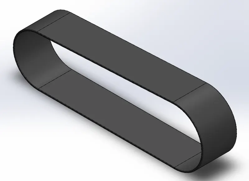
1, Transmission Belt:
The belt is used to transfer power from the engine output shaft to the Gearbox Input Shaft. Generally, it is made up of polyester material with a layer of kevlar and a sandwich of metallic wire.
The feature used for this model are Offset, Fillet and Boss exclude.
2, Fenders:
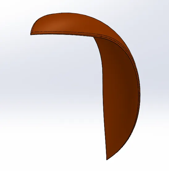
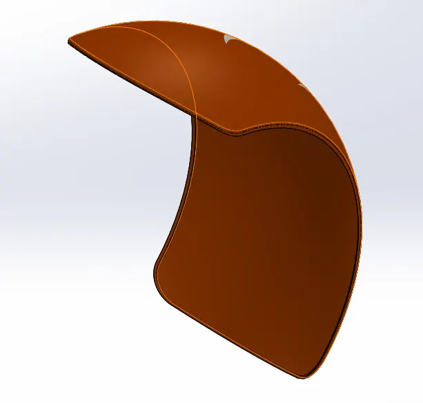
It frames the wheel, its primary purpose is to prevent sand, mud, rocks, liquids from being thrown into the air by the rotating tire.
The feature used for this model is Revolve, Split and Fillet.
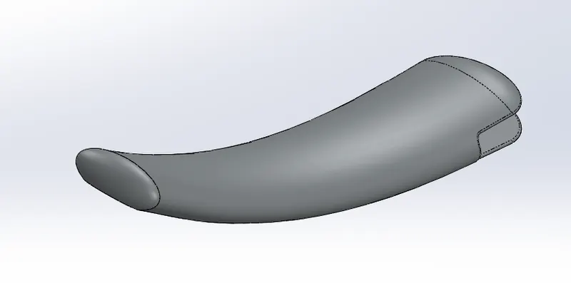
3, Kick Stand:
A Kick Stand helps to support the motorcycle when it's parked so it doesn't tip over.
The feature used in the model is Loft and dome.
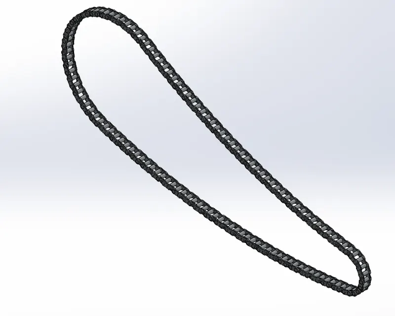
4, Chain:
The chain is a power transmitting Unit, It transmits power from the gearbox output shaft to the sprocket attached to the rear wheel. it is a constant velocity drive.
Features used for this model are curve-driven pattern, boss extrude, block (A block is a saved sketch that can prevent redrawing the same sketch multiple times).
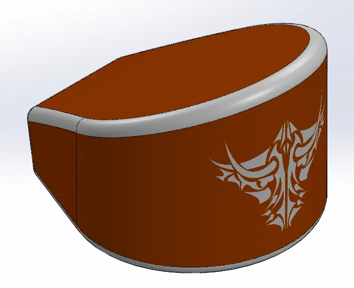
5, Oil Tank:
The oil tank stores oil which is to be supplied to the engine for cooling and lubrication purposes.
Features like Boss extrude, combine and fillet are used.
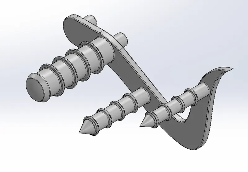
6, Pedal:
The pedal is a lever controlled with the foot to apply the brakes and also to shift the driving gear. Commends used such as Splines, Circles.
Features used for this model are Boss Extrude, Fillet, and Linear pattern.
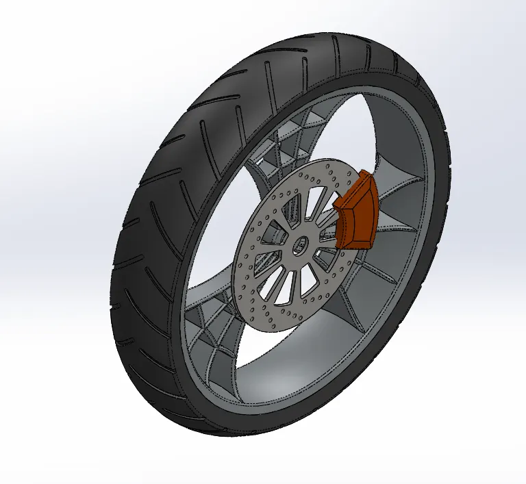
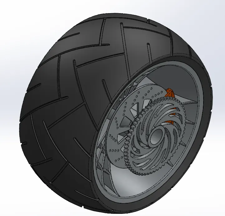
7, Front Wheel and Rear Wheel:
The front-wheel consists of the tire, rotor, caliper, rim, and it is designed by busing sketch tools such as 3_point ar, spline, and sketch entities such as off-set entities, mirror.
Features such as Revolve Boss, Boss Extrude, Cut Extrude, Fillet, Chamber, Mirror, and Circular pattern.
8, Front Fork:
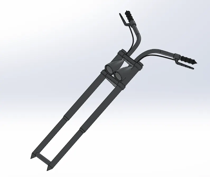
The structure connects the chassis and the front wheel of the bike. It has various mountings on it like headlights, brake wire, and leaver, shock absorber, etc.
Features such as Boss Exture, Revolve, Sweep, Projected Curve, Composite curve, Shell, Dome, Mirror, and Linear pattern were used.
9, Chassis
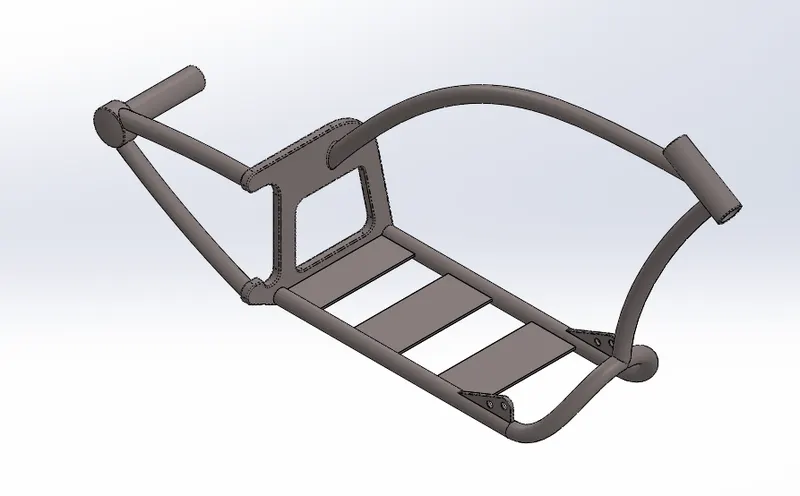
A motorcycle chassis holds everything together from Engine, Suspension, Rear Wheel, Fuel Tank, Handlebars, seat, airbox, etc.
The feature used such as Boss Extrude, Revolve, Sweep, Mirror, Fillet, Chamfer& Projected curves.
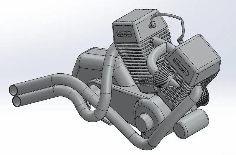
10, Engine:
The Engine includes parts such as spark plug, inlet valve, outlet valve, cylinder, and piston.
The feature used such as Boss Extrude, Cut Extrude, Revolve, Sweep, Projected curve, Composite Curve, Fillet, Chamber, Mirror, Linear Pattern, and Circular Pattern.
11, Gas Tank:
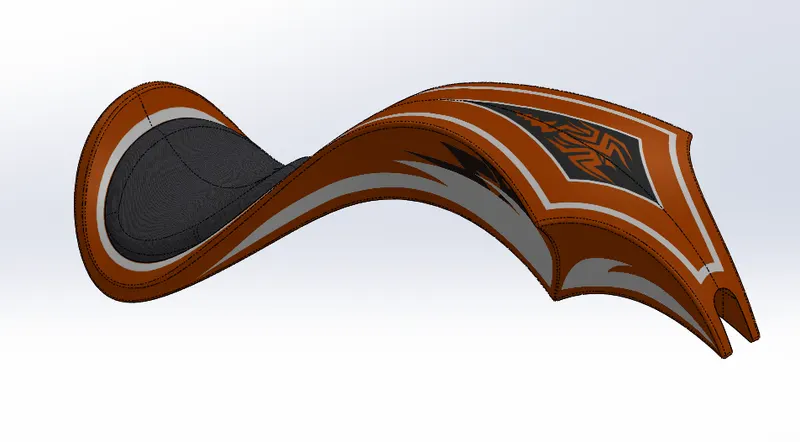
The Fuel Tank stores the fuel required to run the Engine.
Unlike the other part of the chopper, the gas tank was designed by using surface modeling using features like Surface Fill, Boundary Fill, Surface Sweep, Extrude Surface, and Projected curves.
Assembly of American Chopper:
All the parts are assembled in the Solidworks Assembly file by inserting each part, one after the other using suitable mate relation.
MATE:
Mates create a geometric relationship between assembly components. As define the allowable direction of linear or rotational motion of the components. We can move the component within its degree of freedom, visualizing the assembly behavior. Some of the mates used during the assembly process are
Angle mate, Reference Entity of angle mate, Coincident Mate, Concentric Mate, Distance Mate, Lock Mate, Parallel and Perpendicular Mate, Tangent Mate.
1, Front View of the assembled Chopper
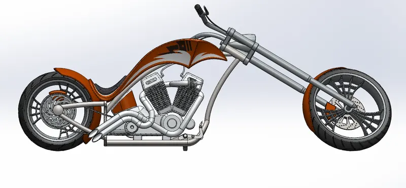
2, Side View of the assembled Chopper
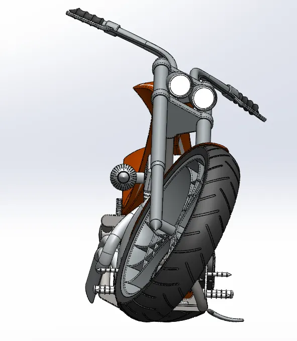
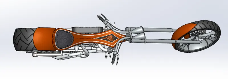
3, Top View of the assembled Chopper
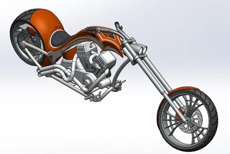
4, Isometric View of the assembled Chopper
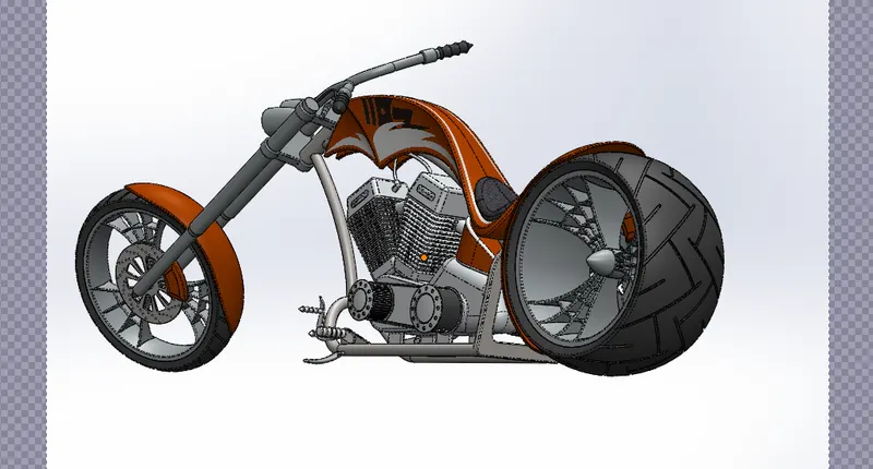
5, the Camera view of the assembled Chopper
Rendering of American Chopper:
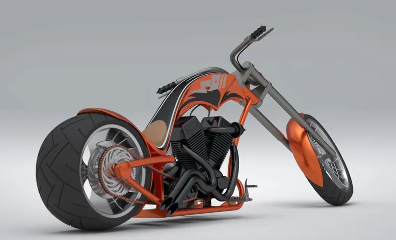
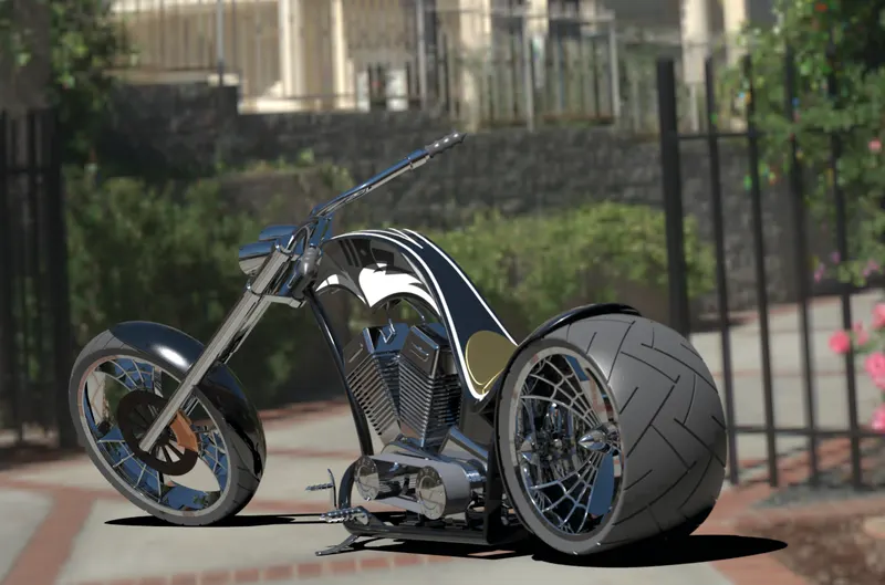
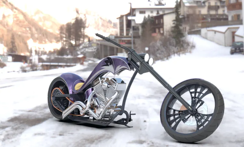
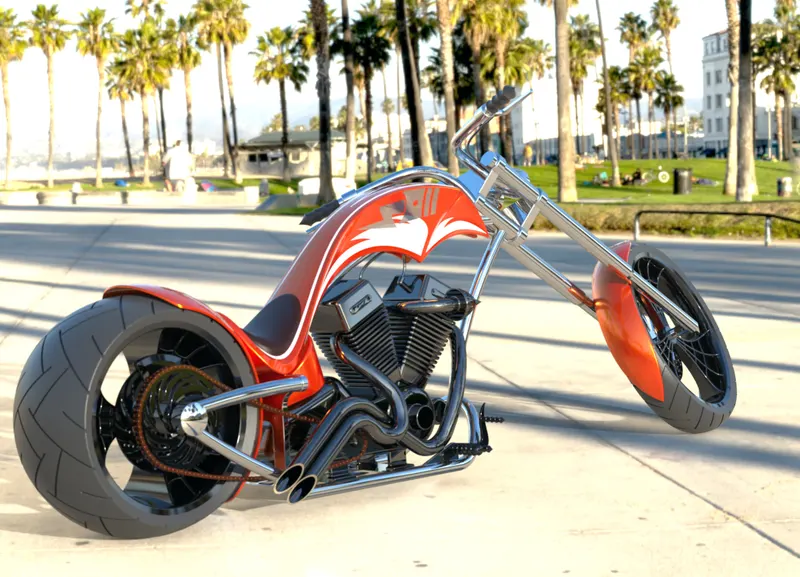
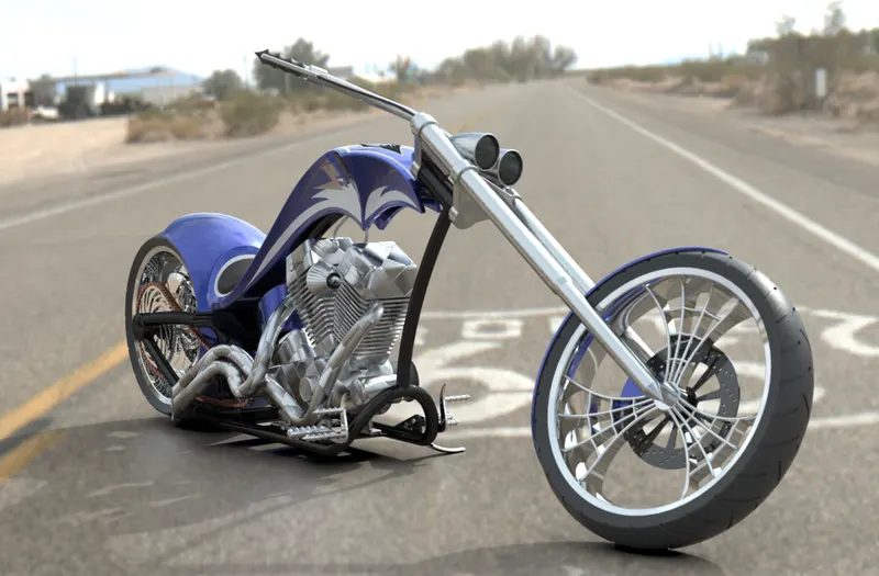
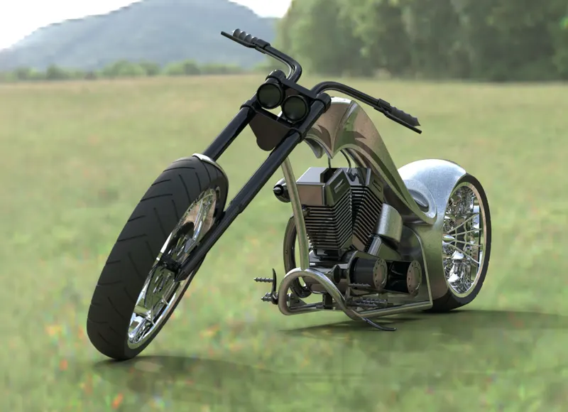
SolidWorks Visualize allows us to leverage our 3D CAD data to create photo-quality content in the fastest and easiest way we can form images to animations, interactive web content, and immersive Virtual Reality. Bringing your product to life. Solidwork Visualize is the camera for the CAD data.
The Rendering Image of the Assembled Chopper is shown below:
Conclusion:
Based on this design of model and assembly I have concluded that I have successfully learned to use surface and solid modeling features and also learned to Render the model using Photoview 360 and Solidworks Visualize.