Photo Realistic Rendering
THE AMERICAN CHOPPER
- OBJECTIVE : The Main Objective of the Project is to Design and Model a Bike named "THE AMERICAN CHOPPER" with the help of Designing Software and Render it to give it a Photo Realistic View.
2. INTRODUCTION : The AMERICAN CHOPPER is a Famous Single Seater Freeway Bike from the late 80's. It was Designed in purpose of giving Bikes an Asthetic Look.It's Elongated
Front Suspension along with a Comfortable Seating Arrangement adds in the looks.The V Shape 2 Piston Engine increases the Power of the Bike. The Corroded
Seina Paint on the Body along with Dual Disc Caliper Braking System adds in the Asthetics.
The Modelling of the Bike is done in the Solidworks Software.The Assembly is first Disintegrated into Parts which then are
Individually Modelled.Solidworks is one of the Most User Friendly Software which helps in Modelling of many Complex Components.Complex Parts viz Oil Tank,Gas
Tank,V2 Engine .etc are easily Modelled in Solidworks.Many Complex Parts can easily be Assembled in Solidworks.A Photo Realistic View can be given to Assembly
with Realistic Background Scenes with the help of Solidworks.
3. DESIGN METHODOLOGY :
METHODOLOGY FLOWCHART
REVERSE ENGINEERING OF THE ASSEMBLY MODEL
` 
STUDY DIFFERENT PARTS OF THE BIKE AND TO ANALYSE WHAT
FEATURES TO BE APPLIED ON THEM
IN PARTS SECTION OF SOLIDWORKS BY USING DIFFERENT FEATURES THE PARTS ARE MODELLED
WITH PROPER DIMENSIONS
THE DIFFERENT PARTS OF BIKE ARE MATED IN ASSEMBLY SECTION OF THE SOLIDWORKS
THE ASSEMBLY OF THE BIKE IS RENDERED IN THE SOLIDWORKS VISUALIZE
4. DESCRIPTION :
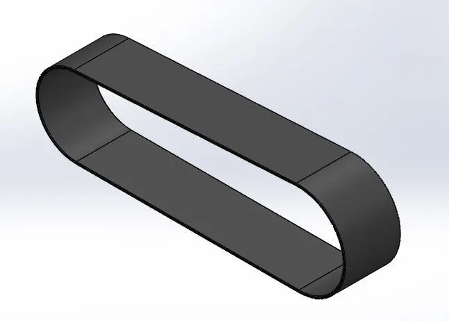
1) Transmission Belt:
* The Features used in Transmission Belt are Boss Extrude and Fillet.
* The Transmission Belt is used to connect Two Mechanical Shafts to Transfer Speed.
2) Kick Stand :
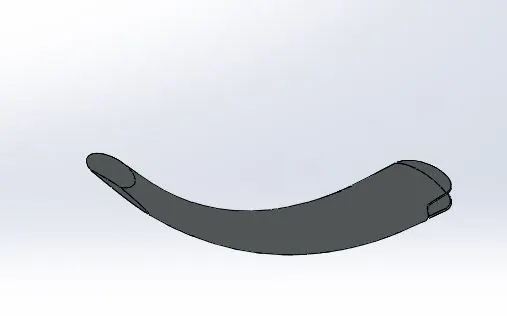
* The Features used in Kick Stand are Loft to connect two elipse of different Dimensions,Two elliptical Domes,Cut Extrude for Clamping
the Kick to the Bike,Split tool to Create a Flat Surface to Rest the Stand,Boss Extrude for the Pivot and lastly the Fillets are applied on
all the curved edges.
* The Kick Stand is used to Rest the Load of Bike on to the Floor.
3) Front Fender :
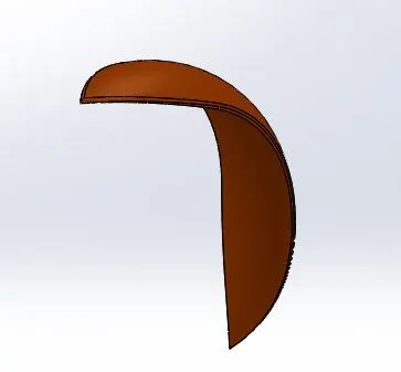
* The Features used in Front Fender are Revolve ,Split Tool to give a Spline Shape Cut on Both ends and Fillet on the Outside Edge.Appearance
Feature is applied to give it a Siena Paint.
* The Front Fender acts as a Mudguard for the Front Wheel.
4) Rear Fender :
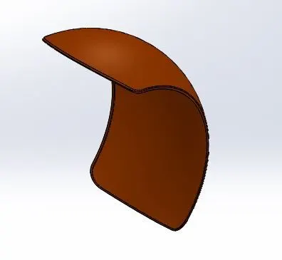
* The Features used in Rear Fender are Revolve,Split Tool to give Spline Cut on one end,Fillet on Outside Edge and Shell Feature. Appearance
Feature is applied to give it a Siena Paint.
* The Rear Fender acts as a Mudguard for the Rear Wheel.
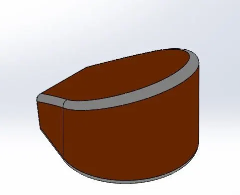
5) Oil Tank :
* Two Boss Extrudes are used Perpendicular to each other and Combine Feature is used which Create the Combined Shape of the Two.Fillets are Applied
at the Edges and lastly the Shell Feature is used to make the Tank Hollow. Appearance Feature is applied to give it a Siena Paint.
* The Oil Tank is fitted between the Gas Tank and Engine.It is used to Supply Oil to the Engine.
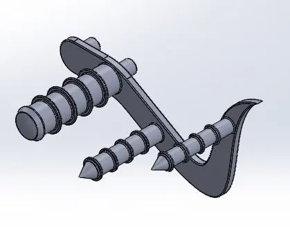
6) Pedal :
* The Complex Shape of the Pedal is Boss Extruded First.Then two Bosses are Extruded for Clamping of Pedal.Then Revolve Feature is used for the Foot
Rest and Boss Extrude is used for the Brake Lever.Champer is applied onto the Brake Lever.Linear Pattern is used to Pattern the Rings on Foot Rest
and Brake Lever.Lastly Fillets are applied on the Edges .
* The Pedal is Clamped on the Chassis.It is used for applying Brakes or Changing Transmission.
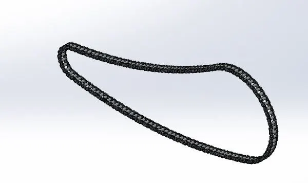
7) Chain :
* The Sketch of Boundary of the Chain is made first.Then the two Chain Links are attached to each other and Boss Extruded.Then the Pins are Extruded and
inserted in the Chain Link Slots.Fillet is applied to the Pin and Chain Links and a Linear Pattern is applied.Then the Chain Links are Mirrored along the pin
by the Mirror Feature.
* It is used to Transmit Speed from Sprocket of the Engine to the Sprocket of the Rear Wheel.
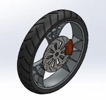
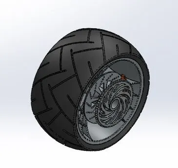
8) Front Wheel :
* Revolve Feature is used to make the Rim of the Wheel.By Boss Extrude and Cut Extrude Spider Web Profile of the Rim is made.Then the Brake
Rotor is made by Boss Extrude.The profile on the Rotor is made by Cut extrude and Linear Pattern.The Tyre around the Rim is made by the
Revolve Feature. The Profile on the Tyre are made by Cut Extrude.The Caliper is made by Boss Extrude and Champer.
* It is Located on the Front Fork of the Bike.It helps in movement of the Bike.
9) Rear Wheel :
* Revolve Feature is used to make the Rim of the Wheel.By Boss Extrude and Cut Extrude Spider Web Profile of the Rim is made.Then the Brake
Rotor is made by Boss Extrude.The Profile on the Rotor is made by Cut Extrude and Linear Pattern.The Sprocket is made by Boss Extrude and
the Teeths of the Sprocket are made by Cut Extrude and Linear Pattern. The Tyre around the Rim is made by the Revolve Feature. The Profile
on the Tyre are made by Cut Extrude.The Caliper is made by Boss Extrude and Champer.
* It is Located at the Rear End of the Chassis.It helps in movement of Bike.
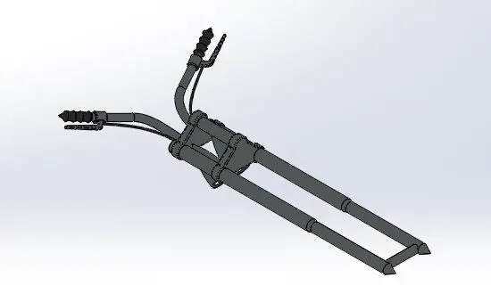
10) Front Fork :
* The Revolve Feature is used to make one side of Suspension Rod.The Clamps on the Rod are made by Boss Extrude and Linear Pattern.The Revolve
Feature is used to make the Headlight between the Clamps.Dome and Fillets are applied on the Headlights.The Profile of the Handle is made by
Project Curve Feature.Lastly the Mirror Feature is applied.
* It is Located at the Front End the Chassis.It helps in Riding and giving Direction to the Vehicle.
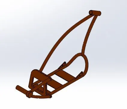
11) Chassis :
* By using Projected Curve Feature two Curves are combined to form a Profile which is the bottom of the Chassis.Then Sweep Feature is used and
the Profile is then Mirrored.Boss Extrude and Cut Extrude is used for the Vertical Back Frame.Champer and Fillets are applied on the Edges.
Sweep Feature is used to connect Two Profiles from the Back Frame onto the Rear Wheel.Boss Extrude is used for the Rear Wheel Axle.Sweep
Feature is used for the Upper Profile where the Gas Tank rests.Revolve Feature is used for the Upper Hub where the Front Fork rests. Appearance
Feature is applied to give it a Siena Paint.
* The Chassis is the Soul of the Bike.All the components rests on the Chassis.
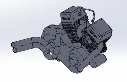
12) Engine :
* Boss Extrude is used to make the Lower Portion of the Engine.Revolve Feature is used to make the Rotating Hub outside the Engine where the
Transmission Belt rests.Boss Extrude and Circular Pattern are used to make the Straps on the Hub.Boss Extrude is used to make the Starter Motor.
Boss Extrude,Champfer,Fillet,Cut Extrude and Mirror Feature are used to make the Cylinders of the Engine.Boss Extrude is used to make the Clamps
and Sprocket.Sweep and Revolve Feature is used make the Air inlet of the Engine.Combine Curve and Sweep Feature are used to make the Exhaust
of the Engine. Sweep Feature is used to make the Gas Inlet.
* Engine acts as a Main Source of Power to the Bike.The Engine uses Fuel and burns it to produce Mechanical Power.
13) Gas Tank :
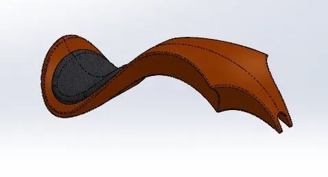
* Surface Sweep Feature is used to Sweep the Surface of the Gas Tank.Surface Trim Feature is used to give the Curved Profile to the Tank.
Surface Loft Feature is used to give a Loft Curve.Projected Curve is used to create the Lower Profile of the Tank.Mirrior Feature is used to
Mirror the Half Side of the Tank.Split Line and Surface Extrude are used to make the Seat.Cut Sweep is used to Create a Slot in the Upper
Part of Tank which Fits into Chassis.Fillets are applied on the Seat and Edges. Appearance Feature is applied to give it a Siena Paint.
* It is Mounted at the Upper Frame of the Chassis.It Supplies Fuel to the Engine.
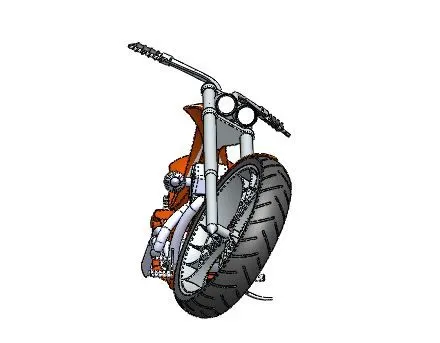
5. ASSEMBLY : In Assembly different Parts of Bike are Assembled on the Chassis by using different Mates such as Co incident Mate,Concentric Mate,Angle Mate .etc
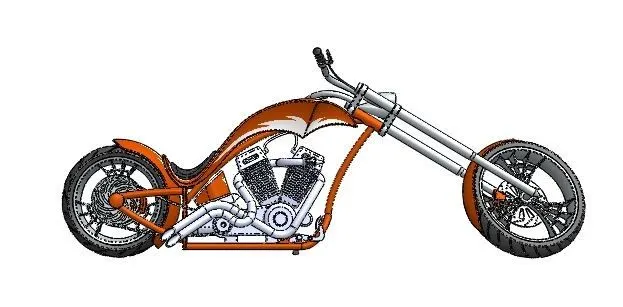
FRONT VIEW
SIDE VIEW
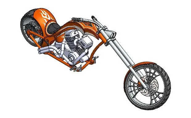
ISOMETRIC VIEW
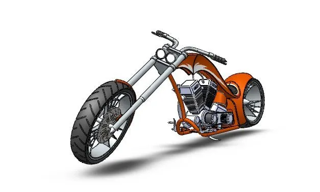
CAMERA VIEW
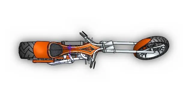
TOP VIEW
6. RENDERING :
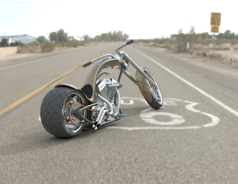
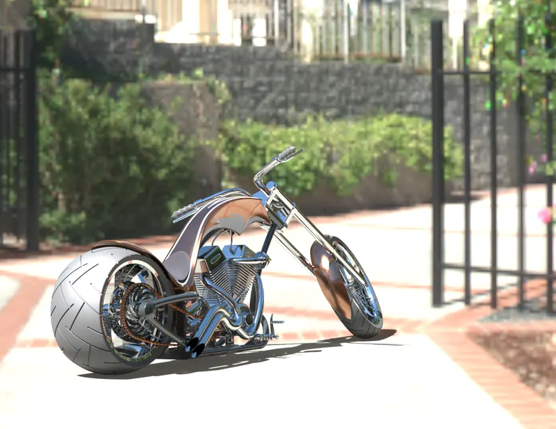
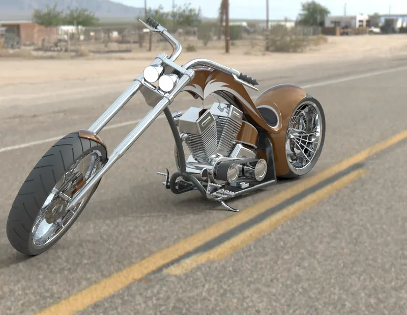
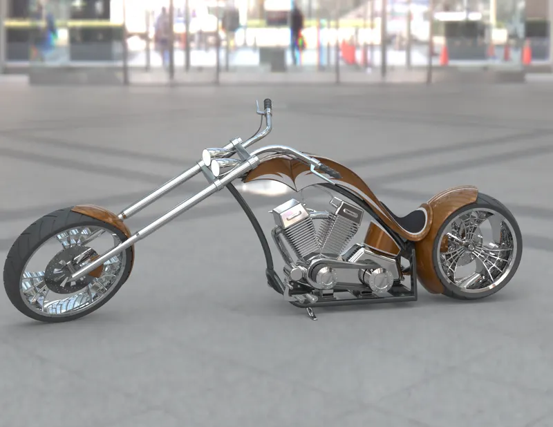
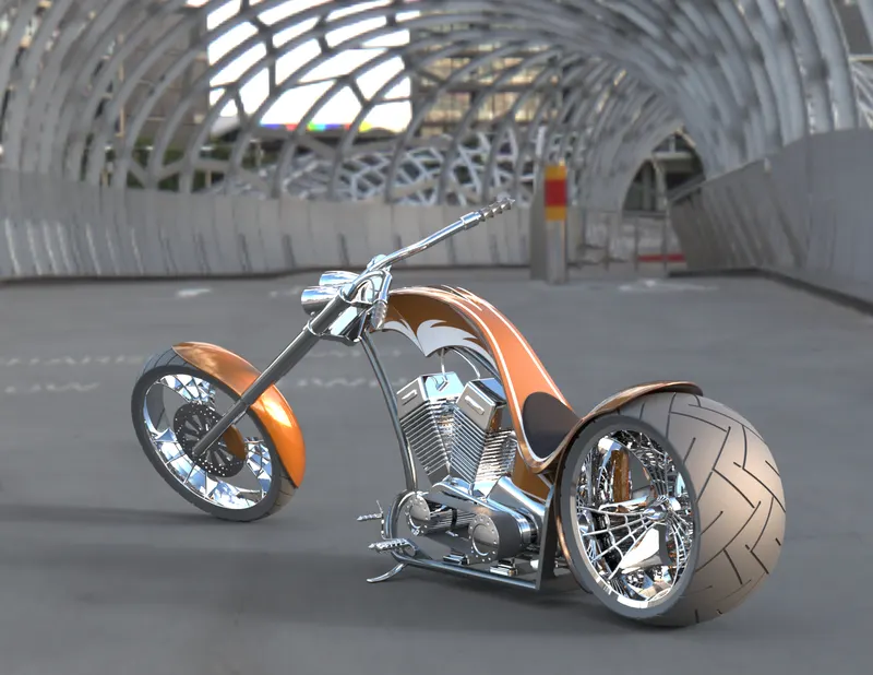
The Rendering of the Bike is done in Solidworks Visualize.The Rendering gives a Photo Realistic View to the Model.Different Scenes can be setup in the Backgroud by
applying HDR Environment. Brightness of the Scenes can be changed with the Brightness and Gamma Value.The Size and Height of the Model can be adjusted
according to the scenes.The colour of the Model can be changed in the Appearance Section.The Rendering Quality can be adjusted acoording to the Passes given
to the Render.
7.CONCLUSION :
Hence, the Design,Modelling and Rendering of the AMERICAN CHOPPER was Studied Completely and Sucessfully Executed.