Advanced Sheet Metal Design Using NX Cad Challenge_6_Bracket
BRACKET
USING
NX CAD
SHUBHAM H POTBHARE
OBJECTIVE
In this project we are going to learn the entire modelling of Bracket using NX Cad.
INTRODUCTION
NX Cad 12.0.1 version is used for modelling. The main plate of Bracket is made by contour flange. Normal cut-out is used to remove the unwanted part. Break corner is used to give fillet at the corners.
DESIGN METHODOLOGY



DESCRIPTION
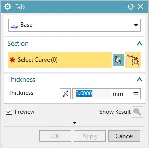
1) TAB: This feature is used to create a base feature by extruding a sketch along a vector by a thickness value or by adding material to existing faces and bend regions of a sheet meta
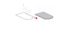
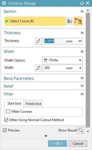
2) CONTOUR FLANGE : Contour Flange is used to create a flange by extruding a sketch along a vector, or by sweeping a sketch along an edge or chain of edges. One can use the contour flange as a base feature of a new sheet metal part and add contour flange as a base feature.
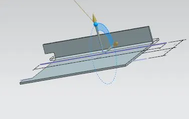
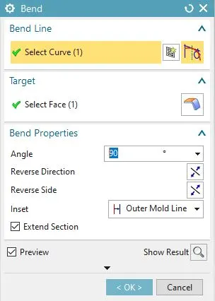
3) BEND : The bend feature is used to give an angular bend to the tab.
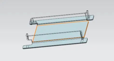
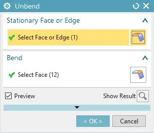
4) UNBEND : The unbend feature is used to make the bend surfaces flat with respect to the base plate.
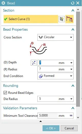
5) BEAD : It lifts material along the contour of a sketch that stimulates a stamping tool. It is used for giving strength to the sheet metal.
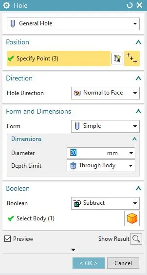
6) HOLE : It adds a hole to one or more solid bodies in a part or an assembly with options for counterbored, countersunk and threaded.
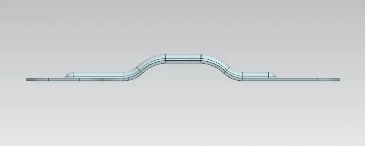
FRONT VIEW
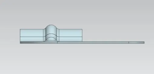
SIDE VIEW
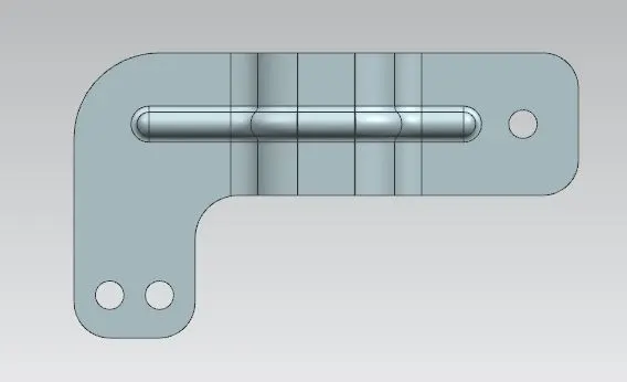
TOP VIEW 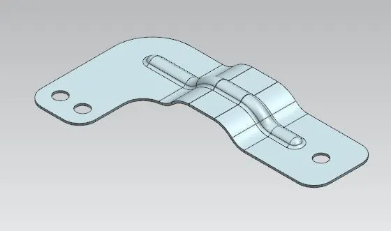
ISOMETRIC VIEW
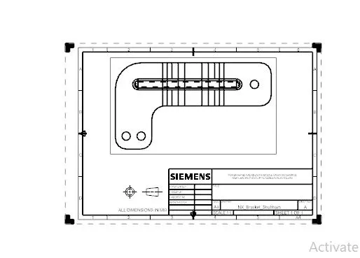
DRAFTING