Modeling, Assembly And Photo Realistic Rendering Of American Chopper Using SolidWorks
DESIGN OF AMERICAN CHOPPER
OBJECTIVE
The objective of the project is to create concept sketches, model the best design using SolidWorks and assemble the components to obtain a fully assembled model of an American Chopper.
INTRODUCTION
The American chopper is designed and developed in a step by step process.
- Creating concept sketches and choosing the best design based on the requirements.
- Modeling the components with appropriate dimensions.
- Providing realistic appearances.
- Assembling the components.
- Rendering of the assembled model.
DESIGN METHODOLOGY
The initial step is building a concept model. Rough sketches of different concept of the American Chopper is made. A model is chosen by considering different design parameters.
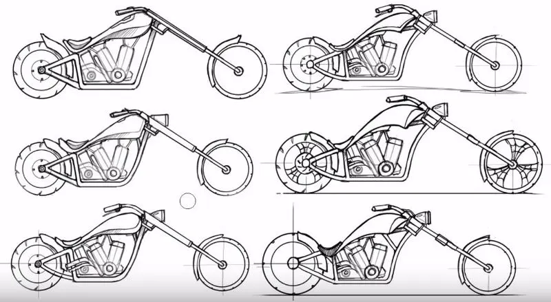
Fig. 1 – Concept Models
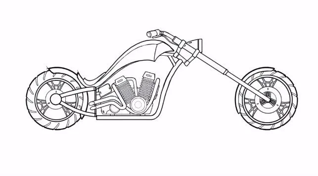
Fig. 2 – Chosen Design for Modeling
The next step in the process is to model each of the component with appropriate dimensions. The components are designed using different solid modeling and surface modeling tools. The components modeled are as following.
|
Fig. 3 – Chain (Rendered ) |
CHAIN Chain is used to transmit the rotary motion from the engine Cam Shaft to the rear wheel. The chain was modeled using several tools. Initially guide path is drawn with an appropriate dimension. Then the chain plates were saved as Blocks and then patterned it along the chain profile. Tools Used – Extrude Boss, Blocks, Patterns, Mirror, Fillet, Combine |
|
|
FRONT FENDER
The Front Fender is a component used to prevent sand, mud, rocks, liquids, and other road spray from being thrown into the air by the rotating tire. The front fonder is relatively less complex in modeling. The Curved body is made using the revolve feature till an appropriate angle. Then the shell feature is used to remove the material and obtain the shape of the Fender. The sharp edges are provided with fillets Tools Used – Revolve, Shell, Fillet |
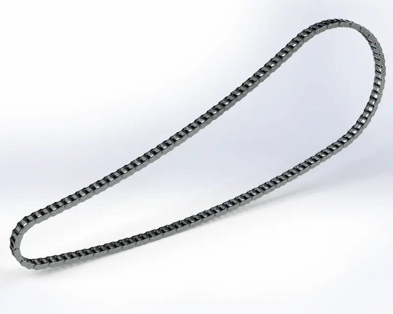
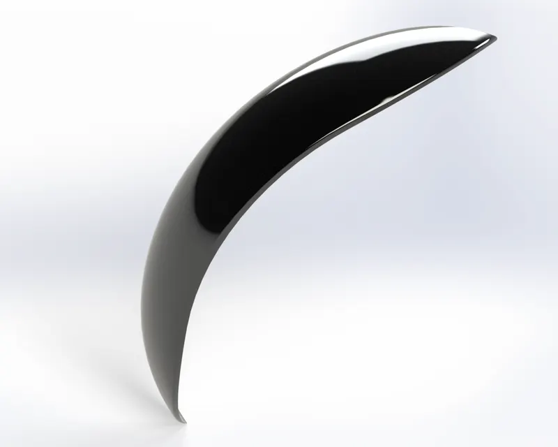 Fig. 4 – Front Fender (Rendered )
 |
Fig. 5 – Front Fork(Rendered) |
FRONT FORK The Front Fork is the component of the bike which steers the vehicle. The Front Fork has shock absorbers which prevent the vibrations from reaching the riders. The Frond Fork was designed by revolving a long tube with the dimension and then extruding the half of triple clamp and then with the help of projected curve, swept circular cross-section to model the handle. Mirroring the whole component and combining the selected bodies. Tools used – Extrude Boss, Revolve Base, Extrude Cut, Projected curve, Swept Boss, Dome, Mirror, Fillet, Chamfer, Combine |
|
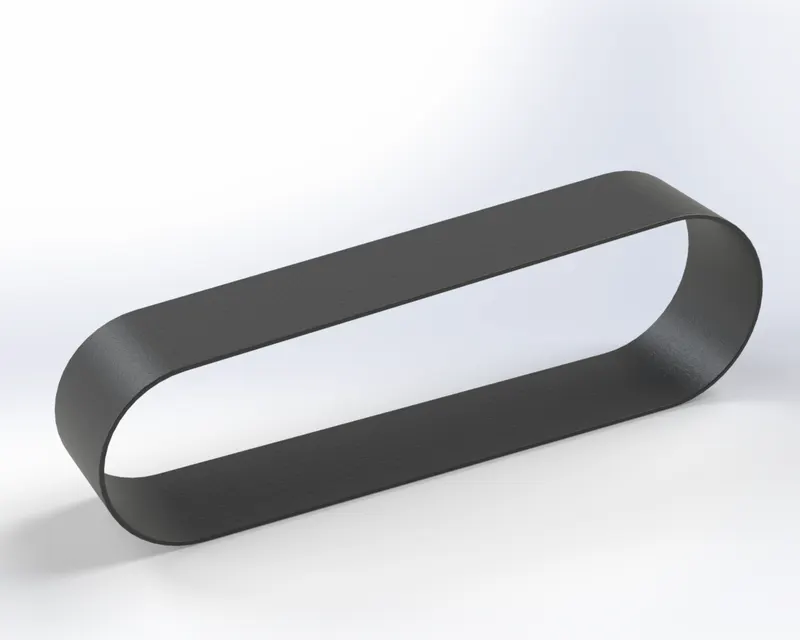
Fig. 6 – TransmissioBelt (Rendered) |
TRANSMISSION BELT
The transmission belt is used to transfer the power from one shaft to other. The profile of the transmission belt is sketched and extruded. Then fillets are applied to the square edges. And appearance of rubber is given. Tools Used – Extrude, Fillets |

|
Fig. 7 – Chassis (Rendered ) |
CHASSIS It is the frame or the structure to which all the other components of the chopper is connected. The component was designed from the blueprint of the chopper. The chassis is modelled using several splines and projected curves. Then the bodies are combined as per the need. Tools Used - Extruded Boss, Revolve Base, Linear Pattern Projected Curve, Mirror, Combine, Split, Chamfer, Fillet |
|
|
Fig. 8 – Fuel Tank (Rendered ) |
FUEL TANK The component where the fuel for the vehicle is stored and supplied to the engine. The Fuel Tank is modeled using several splines and projected curves. Surface modeling tools were used for making the surfaces. The surfaces were then knitted together and converted to a solid model. Tools Used- Swept surface, Loft Surface, Boundary Surface, Project Curve, Knit Surface, Combine ,Shell |
|
|
|
REAR FENDER
The Rear Fender is a component used to prevent sand, mud, rocks, liquids, and other road spray from being thrown into the air by the rotating tire. The rear fonder is relatively less complex in modeling. The Curved body is made using the revolve feature till an appropriate angle. Then the shell feature is used to remove the material and obtain the shape of the Fender. The sharp edges are provided with fillets Tools Used – Revolve, Shell, Fillet |
|
|
Fig. 10 – Kick Stand (Rendered ) |
KICK STAND
The kick stand is the component which supports the chopper and keeps the chopper in a vertical stable position. The Kick Stand is modelled using 2 ellipses connected using a path. The n using the loft the component is modeled. The end is rounded using elliptical Dome. Tools Used- Loft, Dome, Fillets |
|
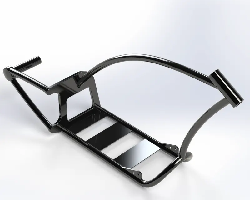
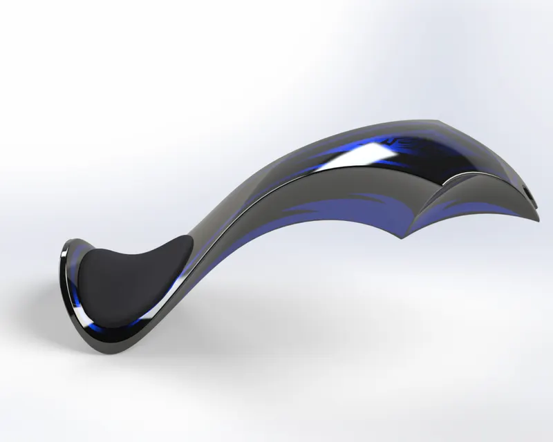
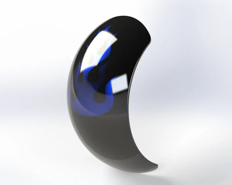 Fig. 9 – Rear Fender (Rendered )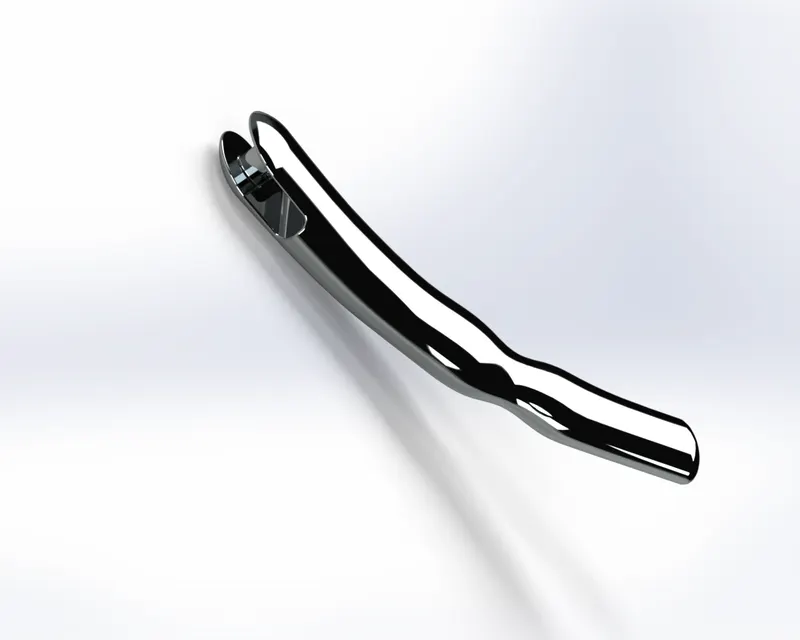
|
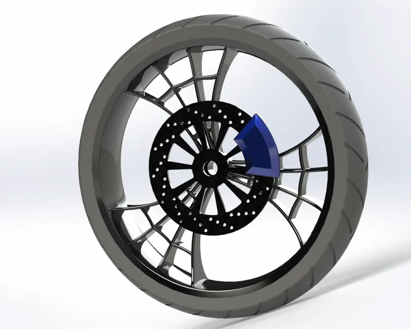
Fig. 11 – Front Tire (Rendered ) |
FRONT WHEEL The tire helps in movement of the vehicle by the rolling motion. The wheel consists of a · Rotor · Caliper · Tire At first, the rim is created using the revolve feature. Then with the help is several splines the web structure is extruded. Then the circular pattern holes are made with appropriate dimension. Then the caliper is designed using extrude and chamfers. Then the tire surface is revolved, and patterns are extruded cut on the surface. Tools Used – Revolve Base, Extrude, Extrude Cut, Revolve Cut, Circular Pattern, Mirror, Chamfer, Combine, Fillet |
|
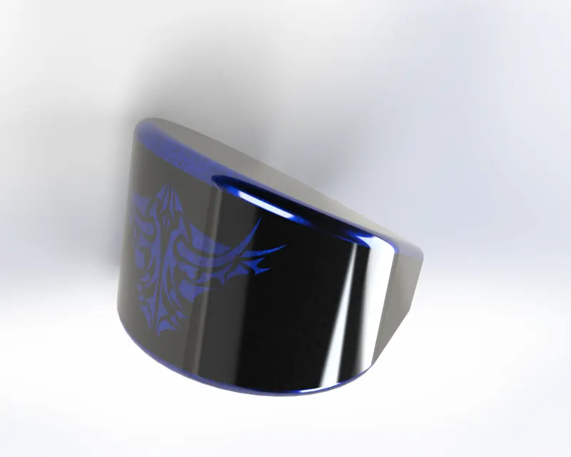
Fig. 12– Oil Tank (Rendered ) |
OIL TANK The oil tank acts as a storage to the engine oil which helps in the smooth running of the engine. The oil tank is less complex component to be modeled. It is extruded using a sketch. Then necessary fillets are applied. Tools Used- Extrude Base, Combine, Shell, Fillet |
|
|
PEDAL
The pedal is the part of the bike where the rider changes the Gear. The pedal plate is modeled by extruding the sketch and then again extruding the cylinder structures. The ring like structures are patterned along the axis of the cylinder. Tools Used- Extrude Base, Revolve Base, Linear Pattern, Chamfer, Dome, Fillet |
|
Fig. 14 – Front Tire (Rendered ) |
REAR WHEEL The tire helps in movement of the vehicle by the rolling motion. The wheel consists of a · Rotor · Caliper · Tire At first, the rim is created using the revolve feature. Then with the help is several splines the web structure is extruded. Then the circular pattern holes are made with appropriate dimension. Then the caliper is designed using extrude and chamfers. Then the tire surface is revolved, and patterns are extruded cut on the surface. Tools Used – Revolve Base, Extrude, Extrude Cut, Revolve Cut, Circular Pattern, Mirror, Chamfer, Combine, Fillet |
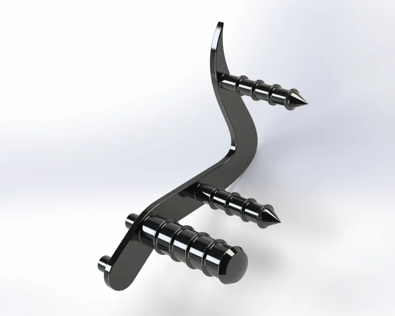 Fig. 13 – Pedal (Rendered )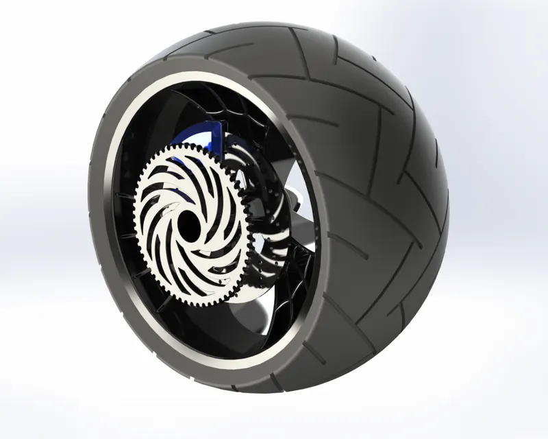
|
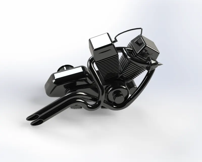
Fig. 15 – Engine (Rendered ) |
ENGINE The engine burns the fuel and produce the power and rotary motion to run the vehicle. The engine is made using several extrudes. The Fins are modeled using cut extrude. Several splines and curves were used to obtain the projected curve for the exhaust. The exhaust is modeled using projected curves. Then chamfers and fillets are given in appropriate locations. Tools Used- Extrude, Extrude Cut, Revolve Base, Revolve Cut, Project Curve, Swept Base, Dome, Combine, Chamfer, Fillet |
The next step is to assemble the model and then give appropriate appearance. All the components are loaded to the assembly interface. Fixing the chassis as the fixed component , other components are assembled with the help of several mates. Several advance mates are also used for assembling. After the assembly, the model is made ready for rendering.
RENDERED IMAGES OF AMERICAN CHOPPER
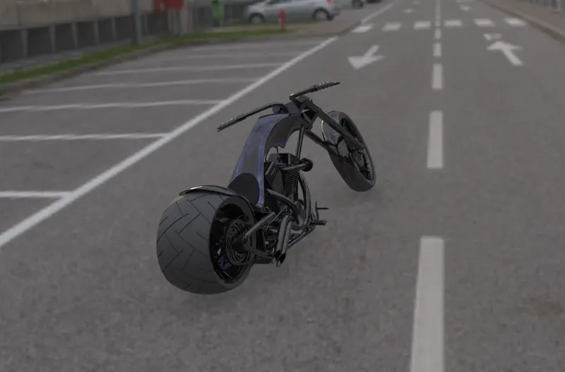
Fig. 15 – American Chopper (Rendered )
------------------------------------------------------------------------------------------------------------