Otto cycle: MATLAB code to solve and compute the thermal efficiency and plot the PV diagram for a IC engine.
Introduction
An air standard Otto cycle is basically an ideal thermodynamics cycle for SI internal combustion engines which describes how heat engine turns the gasoline into motion and thus is also used to determine the efficacy of a heat engine. It is a reversible adiabatic compression and expansion process and there is a constant heat addition (combustion) and heat rejection (exhaust).Here we consider the working fluid is a fixed mass of air undergoing the complete cycle which is treated throughout as an ideal gas. All processes are ideal, combustion is replaced by heat addition to the air, and exhaust is replaced by a heat rejection process which restores the air to the initial state. This cycle tells us the actual state & variation in pressure, temperature and volume of the fuel which is taking place inside the piston.
The major 4 strokes in the Otto cycle is:-
1) Compression stroke
2) Combustion stroke (constant volume)
3) Expansion stroke
4) Exhaust rejection (constant volume)
- Process 1–2 is an adiabatic (isentropic) compression of the charge as the piston moves from bottom dead center (BDC) to top dead center (TDC).
- Process 2–3 is a constant-volume heat transfer to the working gas from an external source while the piston is at top dead center. This process is intended to represent the ignition of the fuel-air mixture and the subsequent rapid burning.
- Process 3–4 is an adiabatic (isentropic) expansion (power stroke).
Process 4–1 completes the cycle by a constant-volume process in which heat is rejected from the air while the piston is at bottom dead center. 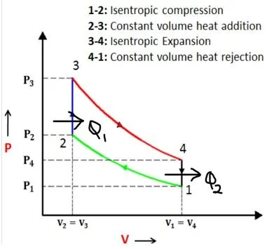
Main governing equation
1) Clearance volume
Space or volume between the top dead center and cylinder head.

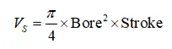
2) Swept volume
The volume that piston displaces or sweeps out as it moves from TDC to BDC or BDC to TDC
3) Initial volume
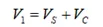
Sum of swept volume and clearance volume
4) Final volume
The clearance volume of the engine is the final volume after compression

5) Compression ratio
The ratio of maximum cylinder volume to minimum cylinder volume i.e ratio of swept volume to clearance volume.

6) Engine kinematic formula

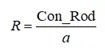
7) Value of R
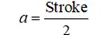
8) Crank pin radius
9) Mathematical representation of the process
*Process 1-2: Isentropic compression
In the given set of question every thing is given in the question. The initial data set is given and defined in the program as input values
*Process 2-3: Constant volume heat addition
p2v2^gamma=p1v1^gamma
p1v1/t1 = p2v2/t2
*Process 3-4: Isentropic expansion
V3=V2
p2v2/t2 = p3v3/t3
*Process 4-1: Constant volume heat rejection
V4=V1
p3v3^gamma=p4v4^gamma
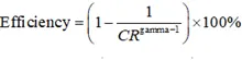
10) Efficiency of Otto cycle
Matlab main Code
clear all
close all
clc

%inputs
gamma = 1.4
t3=2300

%state variables at point number 1 which are usually given in a question or
p1 = 101325 %atmospheric pressure
t1 = 500    %T in kelvin

%engine geometric parameters
bore = 0.1; %size of the piston cylinder
stroke = 0.1; % length travelled by the piston from TDC to BDC
con_rod = 0.15; % length of the connecting rod
cr = 12; % compression ratio is the ratio of volume when the piston is ta TDC & BDC respectively

%calculating the swept volume and the clearance volume
v_swept = (pi/4)*bore^2*stroke;
v_clearance = v_swept/(cr-1);

v1 = v_swept + v_clearance
v2 = v_clearance

%state variable at state point 2
%p2v2^gamma=p1v1^gamma
%p2=p1*(v1/v2)^gamma = p1*cr^gamma(ratio of v1 and v2 is compression ratio)
p2 = p1*cr^gamma;

%p1v1/t1 = p2v2/t2 | t2 = p2*v2*t1/(p1*v1) from the ideal gas law
t2 = p2*v2*t1/(p1*v1);

constant_c = p1*v1^gamma;
V_compression = ishaan_engine_kinematics(bore,stroke,con_rod,cr,180,360);

P_compression = constant_c./V_compression.^gamma;

%state variable at state point 3 (represent the end point of constant
%volume combustion process and t3 is given in the problem itself

v3=v2

%again using the ideal gas law for computing the value of the p3
%p2v2/t2 = p3v3/t3 | p3 = p2*t3/t2
p3 = p2*t3/t2

constant_c = p3*v3^gamma;
V_expansion = ishaan_engine_kinematics(bore,stroke,con_rod,cr,0,180);

P_expansion = constant_c./V_expansion.^gamma;

% state variable at state point 4 (v1=v4)
v4 = v1
%p3v3^gamma=p4v4^gamma
%p4=p3*(v3/v4)^gamma
p4=p3*(v3/v4)^gamma
figure(1)
hold on
plot(v1,p1,'*','color','b')
plot(V_compression,P_compression,'color','k')
plot(v2,p2,'*','color','r')
plot([v2 v3],[p2 p3], 'color','c')
plot(v3,p3,'*','color','y')
plot(V_expansion,P_expansion,'color','m')
plot(v4,p4,'*','color','r')
plot([v4 v1],[p4 p1], 'color','k')
xlabel('Volume in m^3')
ylabel('Pressure in pa')
e = (1-(1/cr^(gamma-1)))*100 %gives us the efficiency of engine
grid on
Function code
function [V] = ishaan_engine_kinematics(bore,stroke,con_rod,cr,start_crank,end_crank)

a = stroke/2 ;%crank pin radius
R = con_rod/a; % ratio of connecting rod length and sweppt length

v_s = pi/4*bore^2*stroke;
v_c = v_s/(cr-1);

theta = linspace(start_crank,end_crank,100); % creating an array of theta and 720 gives us 2 cycles for calculation

term1 = 0.5*(cr-1);
term2 = R + 1 - cosd(theta);
term3 =(R^2 - sind(theta).^2).^0.5; % using the element wise operter because there is a arrray involved

V = (1+ term1*(term2 - term3)).*v_c; %we have calculated how the volume races will look like for 2 ccyles

end
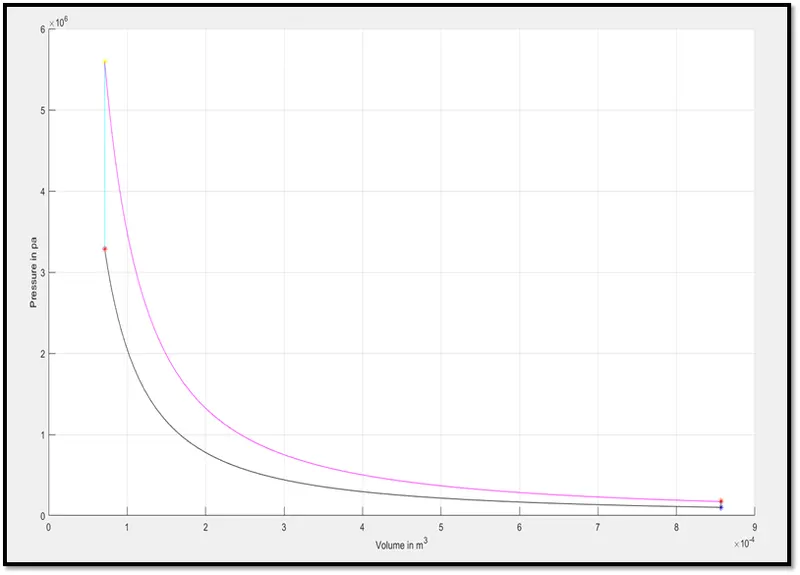
Output
Conclusion
- The total efficiency of the Otto cycle is 62.98 %
- The curve which are plotted can be used to know the state variable at a given interval of time and also know the performance of the engine