OTTO CYCLE
AIM - Write code that can solve an otto cycle and make plots for it
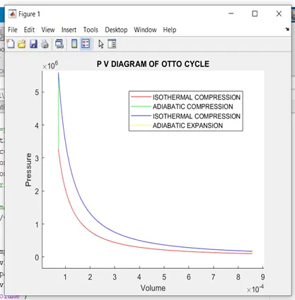
OBJECTIVE- 1. For the OTTO cycle create a Pressure vs Volume graph using MATLAB.
- To output the THERMAL EFFICIENCY of the Engine.
THEORY -
OTTO CYCLE is the working cycle of the Spark Ignition (PETROL) engines. This is the cycle that is most commonly found in automobiles.
The processes involved in the otto cycle are described in the below cyclic diagram
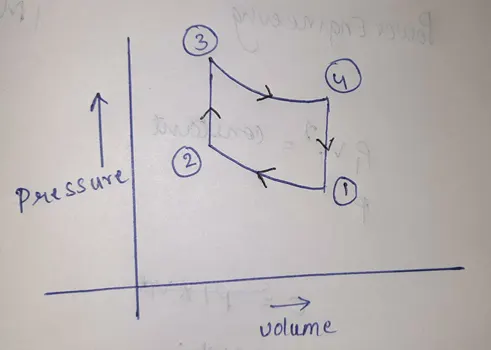
The above cycle represents the OTTO cycle
ISENTROPIC process means the process in which there is no heat transfer between the system and surroundings and it is also called the “REVERSIBLE ADIABATIC PROCESS”.
Process 1 to 2 (ISENTROPIC COMPRESSION) During this phase the piston will be drawn up, so it can compress the fuel-air mixture that entered the chamber. The compression causes the mixture to increase slightly in pressure and temperature
Process 2 to 3(CONSTANT VOLUME HEAT ADDITION OR ISOCHORIC) This is where combustion occurs due to the ignition of fuel by the spark plug. The combustion of the gas is complete at point 3, which results in a highly pressurized chamber that has a lot of heat.
Process 3 to 4(ISENTROPIC EXPANSION) The thermal energy in the chamber as a result of combustion is used to do work on the piston—which pushes the piston down—increasing the volume of the chamber.
(Process 4 to 1): From process 4 to 1, all waste heat is expelled from the engine chamber. As the heat leaves the gas, the molecules lose Kinetic Energy causing a decrease in pressure.
ENGINE GEOMETRIC PARAMETERS
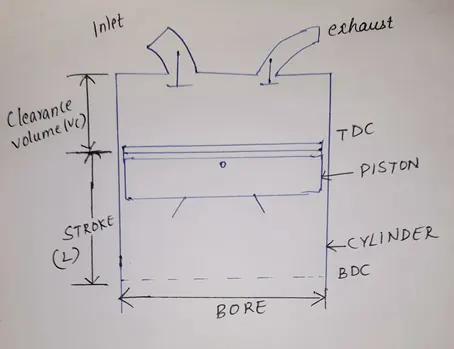
TDC (TOP DEAD CENTRE) – It is the TOP most position of the piston inside the cylinder of an engine
BDC (BOTTOM DEAD CENTRE) - It is the BOTTOM most position of the piston inside the cylinder of an engine.
BORE – It is the diameter of the cylinder of an engine.
STROKE - It is the distance through which the piston moves from the TDC to BDC or BDC to TDC.
CLEARANCE VOLUME - It is the volume between the top dead centre and the cylinder head.
GOVERNING EQUATIONS
SWEPT VOLUME = (pi/4) *bore^2*stroke (cubic centi meter).
CLEARANCE VOLUME= SWEPT VOLUME / (compression ratio-1). (cubic centi meter).
EFFICIENCY CALCULATIONS –
The efficiency of the Otto cycle can be calculated by the below formula
EFFICIENCY = Output / Input
In this case, the output is the work is done and input is the heat supplied
Efficiency = Work done/ heat supplied
= 1- 1/((r)^(gamma-1)).
During the Isentropic process
p2v2^gamma=p1v1^gamma
p3v3^gamma=p4v4^gamma
where p and v are pressure and volume respectively.
By using the ideal gas law equation that is PV = nRT.
Where P is the pressure in pascal
V is the volume
n is the amount of substance
R is the ideal gas constant
T is the temperature
P1v1/t1 = p2v2/t2
Where t is the temperature.
PISTON KINEMATICS
V= (1+ 0.5*(cr-1) * ((R+1-cos(theta)- (R^2-sin(theta)^2) ^0.5) * clearance volume
Where
R is the ratio between Connecting rod length to Crankpin radius
Crankpin radius (a) = stroke/ 2.
PROGRAM
MAIN PROGRAM
clear all
close all
clc
%inputs
gamma = 1.4; % ratio of specific heats
t3= 2300; % temperature at state 3
%state variables at state point 1
p1= 101325; % predefined pressure that is 1atm
t1= 500; % temperature at state 1 in kelvin
% Engine parameters
bore=0.1; %diameter of  bore in centimeter
stroke=0.1; % length of stroke in centimeter
con_rod=0.15; % length of the connecting rod
cr=12; % compression ratio
% calculating swept and clearance volume
v_swept= (pi/4)*bore^2*stroke; % to calculate swept volume
v_clearance= v_swept/(cr-1); % to calculate clerance volume
v1= v_swept+v_clearance; % volume at state 1
v2=v_clearance; % volume at state 2
% state variables at state point 2
% p2v2^gamma=p1v1^gamma/ p2=p1*cr^gamma
p2=p1*cr^gamma;
constant_c= p1*v1^gamma; % definition of the isentropic process
V_compression= enginek(bore,stroke,con_rod,cr,180,0); % calling the function by using the piston kinematics
P_compression= constant_c./V_compression.^gamma;
%ideal gas law %p1v1/t1= p2v2/t2
t2=p2*v2*t1/(p1*v1);

%state variables at state point 3
v3=v2;
% p3v3/t3=p2v2/t2  /p3=p2*t3/t2
p3=p2*t3/t2; % calculating the pressure at state 3 with defined temperature at state 3
constant_c= p3*v3^gamma;
V_expansion= enginek(bore,stroke,con_rod,cr,180,0);
P_expansion= constant_c./V_compression.^gamma;
%state variables at state point 4
v4=v1
%p3v3^gamma=p4v4^gamma / p4=p3(v3/v4)^gamma
p4=p3*(v3/v4)^gamma
% Thermal Efficiency
Percentage_Efficiency = (1-(cr^(gamma-1))^-1)*100 % formula for calculating the efficiency
figure(1) % opens a new figure window
hold on
% for getting the plot and joining them and also includes the kinemtaics of
% the piston
plot(V_compression, P_compression,'color','r')
plot([v2 v3],[p2 p3],'color','g')
plot(V_expansion, P_expansion,'color','b')
plot([v4 v1],[p4 p1],'color','Y')
xlabel('Volume') % to label x axis
ylabel('Pressure')% to label x axis
FUNCTION PROGRAM
function [V]= enginek(bore, stroke, con_rod, cr, start, end_crank)

a = stroke/2; % crank pin radius

R = con_rod/a; % ratio of length of connecting rod to crankpin radius

v_s= (pi/4)*bore^2*stroke; % calculation for the swept volume

v_c= v_s/(cr-1); % calculation for the clearance volume

theta= linspace(start,end_crank,100); % defining multiple values of theta

t1=0.5*(cr-1);

t2=(R+1-cosd(theta));

t3=(R^2-sind(theta).^2).^0.5;

V= (1+t1*(t2-t3)).*v_c; % piston kinematic equation.

end
EXPLANATION OF THE CODE
Step 1- The inputs required for the system are provided i.e gamma and temperature after the compression.
Step 2- The state variables of the system are defined i.e pressure and temperature to calculate the volume at state 1, Consider the Engine parameters such as bore, stroke, connecting rod length and compression ratio.
Step 3 – The values of v1 and v2 can be calculated by calculating the clearance volume and swept volume from the values of engine parameters.
Step 4 – For calculating the value of p2 we can the formula from the isentropic process that is p1v1^gamma= p2v2^gamma and the temperature t2 can be calculated by the ideal gas law that states pv=nRT and from the equation we can derive p1v1/t1= p2v2/t2.
Step 5- For having the exact graph we should consider the piston kinematics as well. For decreasing the complexity and length of the code and function enginek is defined such that it has a code for piston kinematics and the inputs for the code are bore, stroke, connecting rod length, compression ratio, starting crank angle, ending crank angle. For having the different crank angles linspace command is used and the formula for the change in volume with respect to the change in crank angle is given as
V= (1+ 0.5*(cr-1) * ((R+1-cos(theta)- (R^2-sin(theta)^2) ^0.5) * clearance volume.
After defining the function it is called. Depending on this the values of V_compression and P_compression changes.
For calculating the P_compression
P_comoression=constant/ V_compression
Where constant is given as c= p1v1^gamma.
Step 6- Repeat the same steps as above to get the remaining values and we have an input that is T3 for calculating the p3 and V3 is equal to v2 as the volume is constant
Step 7- Repeat the same steps to compute the remaining values.
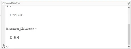
Step 8- The efficiency can be calculated by the formula Percentage Efficiency = (1-(cr^(gamma-1))^-1)*100.
Step 9- Using the plot command the plot is made and labels are given
ERRORS FACED
- Invalid use of the operator
In the inputs to the function the keyword end is used.
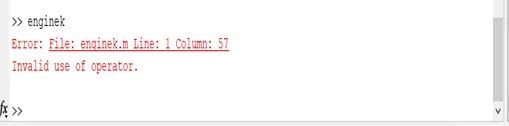
This is rectified by changing end to end_crank.
- The variable p is typed as P
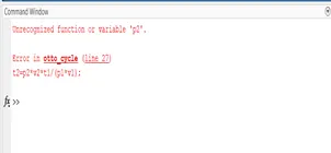
It is rectified by changing P to p
OUTPUT
Otto cycle
EFFICIENCY
The percentage efficiency for the otto cycle for the given engine parameters is 62.98 %
RESULT
Thus the OTTO cycle is studied and the plot is made between Volume and Pressure and also its efficiency has been determined.