Project 3- Study of cantilever beam with different cross-sections like circular, rectangular and I section and to find out the effect of cross-section on the deflection of the beam using FEA technique using Ansys Workbench and results has to be verified using strength of material deflection equations.
Given:
Cantilever Beam;
Material: E = 210 GPa, μ = 0.3
P = 1000 N; L = 1000 mm
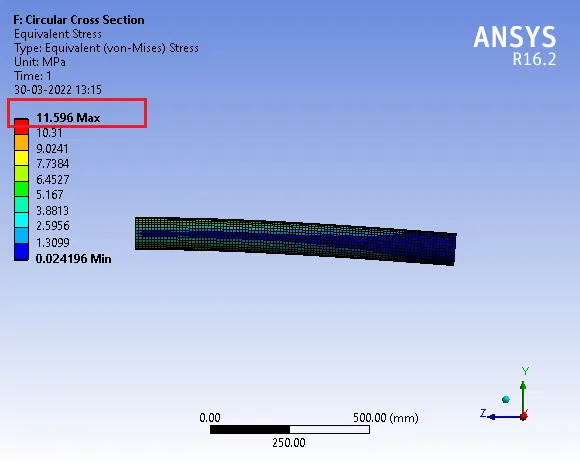
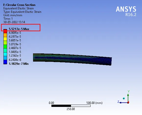
Case 1: Circular cross section
Area: 50 mm Radius
Analytical Method:
Maximum Displacement given by,
δmax = WL3 = 1000 X 10003
3EI 3 X (210x103) X (π/64 x 1004)
δmax = 0.3233 mm
Numerical Solution (Using ANSYS Workbench):
Total Deformation:

Equivalent Stress:
Equivalnet Elastic Strain:
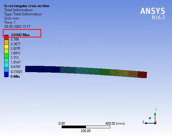
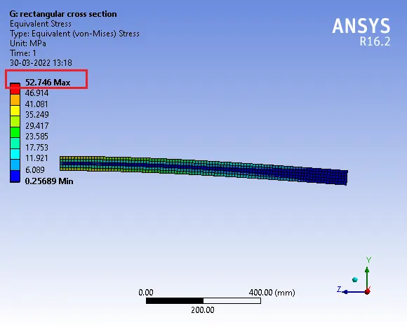
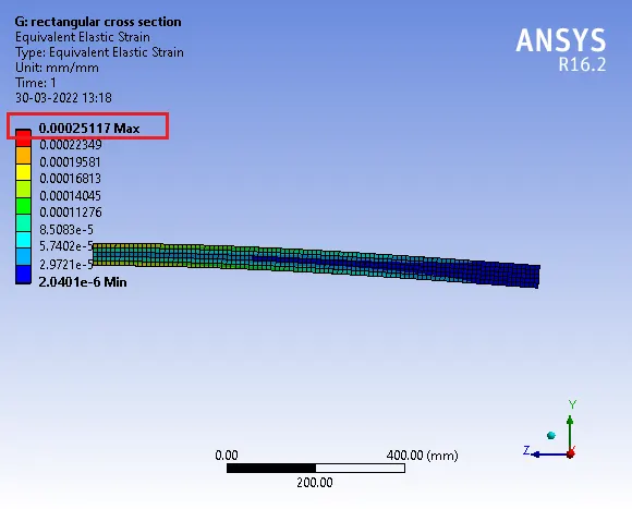
Case 2: Rectangular cross section
Area: 50x50 mm
Analytical Method:
Maximum Displacement given by,
δmax = WL3 = 1000 X 10003
3EI 3 X (210x103) X (50x503/12)
δmax = 3.0476 mm
Numerical Solution (Using ANSYS Workbench):
Total Deformation:
Equivalent Stress:
Equivalnet Elastic Strain:
Case 3: I-section cross section
Area: area equal to area of rectangle
TFw= 50mm TFt=16.67mm BFw= 50mm BFt=16.67mm Wh=16.67mm Wt=16.67mm
Analytical Method:
Maximum Displacement given by,
δmax = WL3 = 1000 X 10003
3EI 3 X (210x103) X (507990)
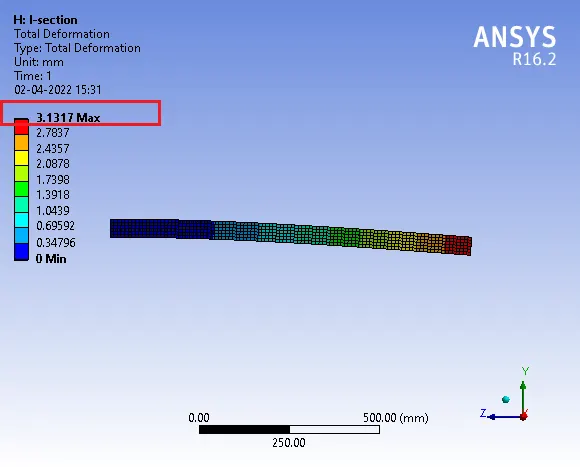
δmax = 3.12 mm
Numerical Solution (Using ANSYS Workbench):
Total Deformation:
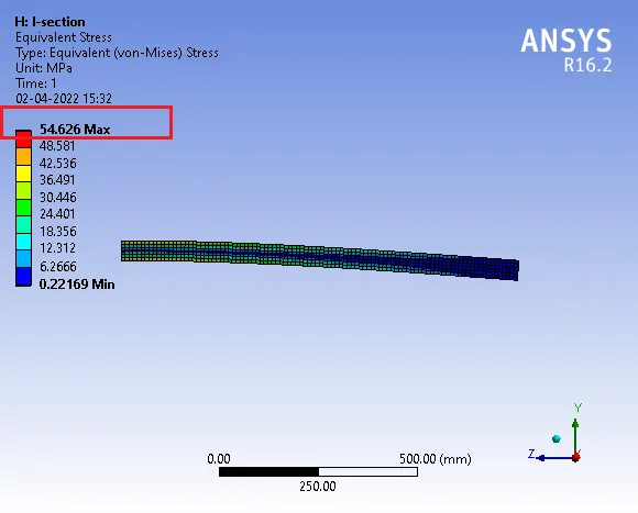
Equivalent Stress:
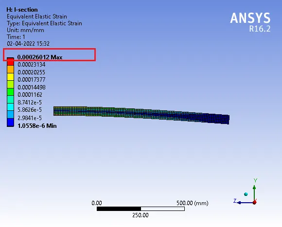
Equivalnet Elastic Strain:
Learning Outcomes:
Learn about geometry creation, Material assignment, Meshing (Element Type), Defining Boundary conditions and post-processing (Results) in Ansys Workbench.
Learn about how different geometry, materials properties and boundary conditions plays a important roles while solving a problems.
Conclusion:
Deformation and stress induced in a beam depends on geometry, Materials properties and boundary conditions.