Modelling of EV using MATLAB and Simulink
Aim: Create a MATLAB model of electric car which uses a battery and a DC motor. To check out performance parameters speed, SOC, current with FTP drive cycles.
Theory:
EV Theory
All-electric cars (EVs), also known as battery electric vehicles, store the electrical energy that powers the motor in a battery pack. The vehicle's electric battery is charged by hooking it into an electric power source. Despite the fact that power generation contributes to air pollution, the EPA classifies all-electric vehicles as zero-emission vehicles because they emit no direct exhaust or tailpipe emissions.
Block Diagram of EV Vehicle
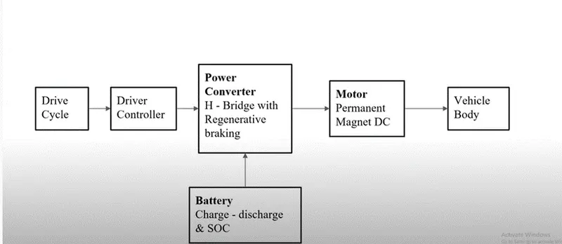
(1) Battery : The battery of an electric car can be charged through the use of ordinary grid electricity at a specialized power station. But aside from the conventional lithium-ion battery technologies, there are also other major battery technologies which can be used for electric cars.Lithium-Ion Batteries : This battery technology gives extra performance and range. However, it also carries the highest price tag. Lithium-ion batteries are lighter than Lead acid and Nickel metal. These are also the batteries used in digital cameras and smartphones.
(2) Motor Controller : The motor controller of an electric car administers its complete operation and the distribution of its power at any given moment. It acts as a floodgate between the motor and batteries. It helps monitor and regulates all key performance indications such as the vehicle’s operator, motor, battery, and accelerator pedal. It has a microprocessor which can limit or redirect current. It is used to either improve the mechanical performance of the car or suit the operator’s driving style. There are also more refined controllers which are capable of greater accuracy and thus, higher efficiency.
(3) Electric Motor: Unlike a gasoline engine with lots of moving parts, a motor only has one moving part. This makes it a very reliable source of motive power. Choosing an electric motor depends on the car’s system voltage. They can be structured to use either AC or DC current. AC motors are less expensive and lighter compared to DC motors. They are also more common and they tend to suffer from less mechanical wear and tear. However, AC technology requires a more refined or sophisticated motor controller
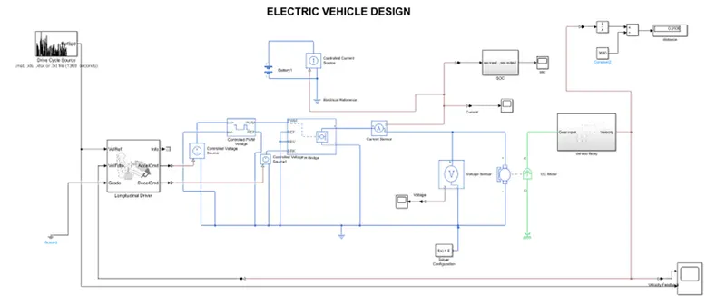
Simulink Model
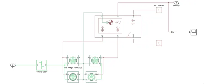
Vehicle Body Sub-System
Simulink Model Explanation
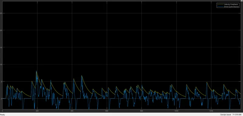
Drive Cycle- UDDS (Urban Dynamometer Driving Schedule) for 1369 sec is used.
1.Tire
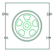
The vehicle is assumed to be a front axle driven (4 wheels - 2 on each axle).
The wheels are modelled using simple Tire, where
H - Hub
S - Tire slip
N - Normal force which is applied to tire
A - Axle Connection
2.Vehicle Body
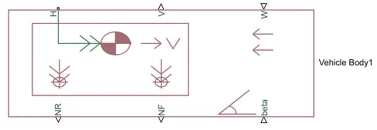
Now we want vehicle body above this four-tire and this vehicle body actually installed in all this four-tire. So, as you can see there are five-terminal to tire which is,
W - Wind velocity
Beta - Grade angle
V - Velocity
NR - Normal force on rear axel
NF - Normal force on rear axel
3.Simple Gear
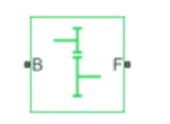
It represents the gear box which connect the motor to rear axle of the vehicle
4.DC Motor
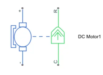
Simulink provides an inbuilt model block for DC motor which converts electrical input into mechanical rotational output.
Note : Here, the blue colour corresponds to the electrical side of the motor and the green colour corresponds to the mechanical side.
Here, the motor field type is kept as Permanent magnet and the model parameterization is done by rated load and speed.
The armature inductance and the mechanical parameters are given their default values.
5.H - Bridge
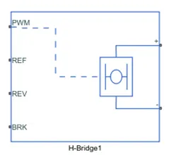
This block represents an H-bridge motor drive. The block can be driven by the Controlled PWM Voltage block in PWM or Averaged mode.where
PWM = Pulse width modulation
REF = Reference
REV = Reverse
BRK = Regenerative braking
6.Controlled PWM Voltage
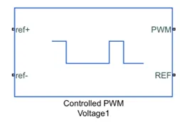
Controlled PWM voltage will actually apply pulses and based along these pulses from the fixed battery voltage. The variable voltage available to motor which is motor speed and torque are going to change.
ref+ = Reference positive for acceleration command
ref- = Reference negative for Deceleration command
PWM = Pulse width modulation connected to H-bridge
REF = Reference connected to H-bridge
7.Controlled Voltage Source
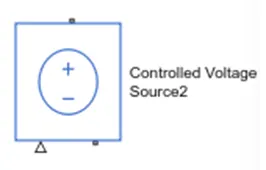
Controller is work on logic level and this is power level, so we will require a controlled voltage source for given output of this block.
8.Longitudinal Driver
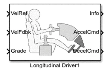
A parametric longitudinal speed tracking controller for generating normalized acceleration and braking commands based on reference and feedback velocities.
9.Drive Cycle
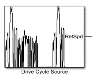
Drive cycle is given as input to model and is nothing but at what speed you want to run your vehicle.
10.Battery
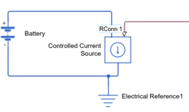
We are going to connect battery in a such way that it is going to get discharge according to current which is taken out from dc motor. This battery connects to controlled current source which will discharge the battery according to current taken from dc motor.
Simulation Result:
Vehicle Feedback
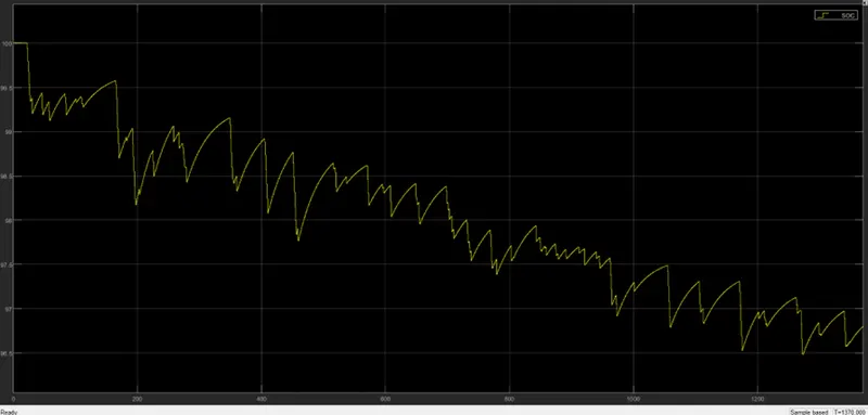
Battery SOC
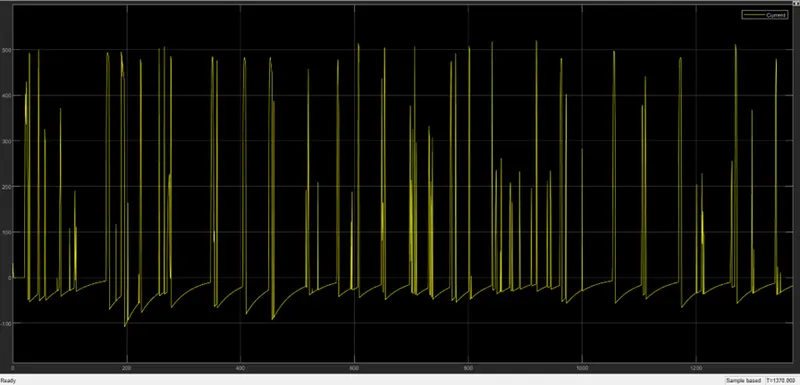
Current
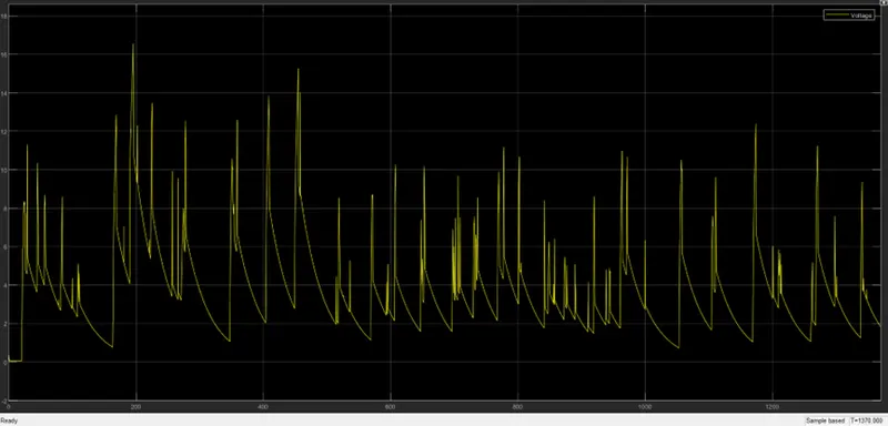
Voltage
Distance – 0.9106 km
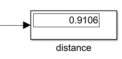
Observation: It is observed that after the drive cycle operation time i.e., after 1369 seconds the SOC is around 96.5% managing to cover a distance of 0.9106km
Conclusion:
The model was successfully run for simulation under the standard UDDS drive cycle. different powertrain blocks provided by Simulink which can be used to simulate a vehicle model.
Reference: