Modelling of 25 storey building with the specified properties using ETABS
Aim & Introduction
The objective of this project is Seismic Analysis of 25 storied RCC Structural Building using ETABS. In World wide there is a high demand of high rise building constructions on urban areas due to population increased. While going for such tall structural design apart from gravity loads we need to consider the lateral load design like wind or seismic load parameters depends on the location which we plan to construct. The parameters as fundamental natural period of vibration, Torsional irregularities, vertical irregularities and storey drifts were analyzed and checked
Procedure in Detail
Step by Step Procedure for ETABS Software
1. Model the structure using beam-column centre line
2. Define Materials,Frame Properties and assign
3. Define and Apply Loads and Load Combinations
4. Check Model and Analyze the Structure.
5. Result output
The structure has been modelled using ETABS.
The following specification are given
Type of Structure- 25 Storeied RCC Structure
Structural Element Sizes
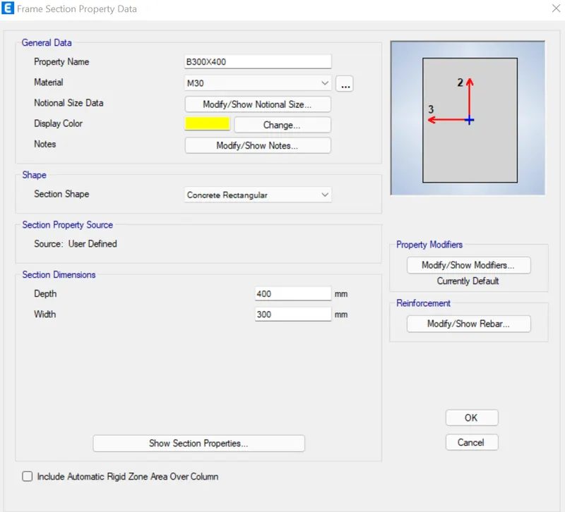
- Beams : 300 × 400 mm
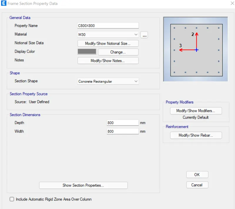
- Columns : 800 × 800 mm
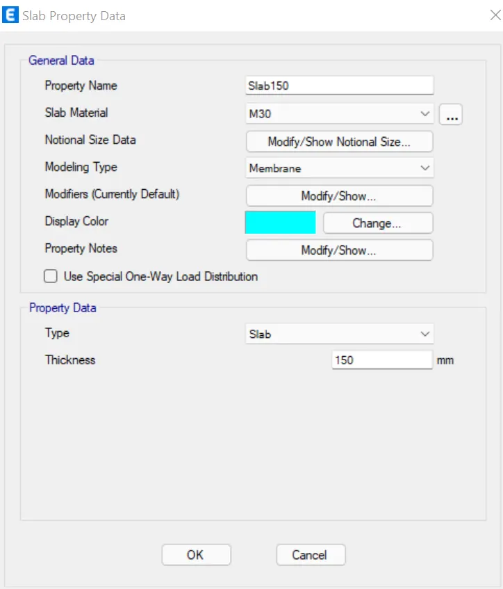
- Slab : 150 mm thick
Material Properties
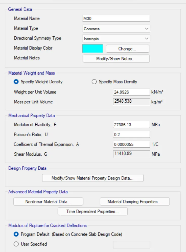
- Grade of Concrete : M30
- Grade of Steel Reinforcement Bars : Fe 415
Loading
- Dead Load on beams from infill wall : 10 kN/m (Let us assume the same for roof floor in view of parapet)
- Live load on floor : 3 kN/m2 (Let us assume the same for roof floor)
- Buildings are assumed to be pinned at the base
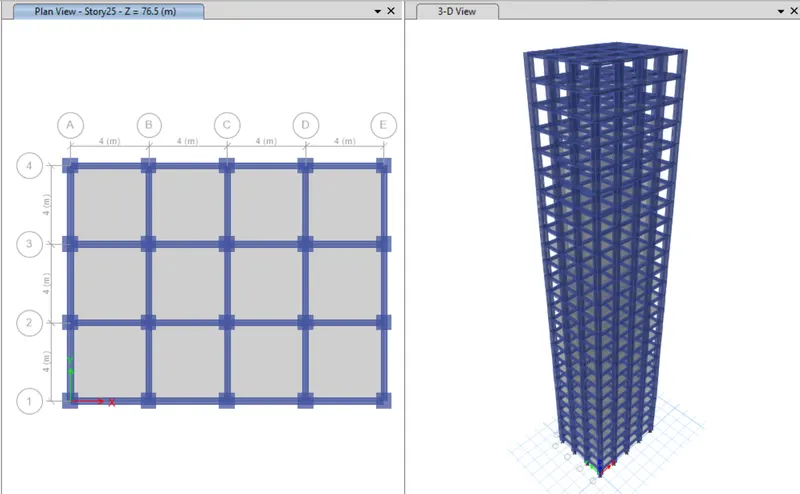
1. Modelling
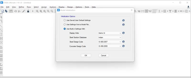
Open ETABS --> Select File---> New Model---> The Model Initialization dialog box has been displayed--> Give the configuration as required. As we design the structure based on Indian standards therefore provide the codes and units by select the option use built-in setting and give the details as required. Once given click OK button. The reference image as shown in Figure 1
Once Click OK New Model Quick Templates will display--> On add Structural objects select Grid only options--> Choose Custom Grid Spacing--> Grid Edit Data
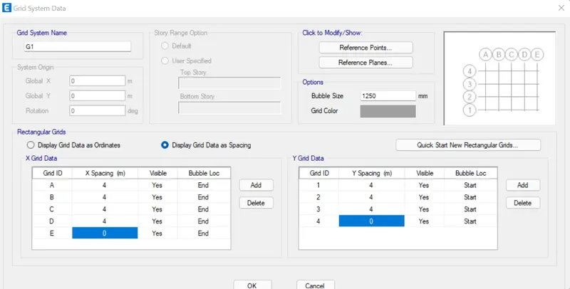
Add grids either by choosing the option Display Grid Data as Coordinates or by Display Grid Data as Spacing on Rectangular Grids.
I choose Display Grid Data as Spacing. As per the Plan give the details on X Grid Data and Y Grid Data and click OK.
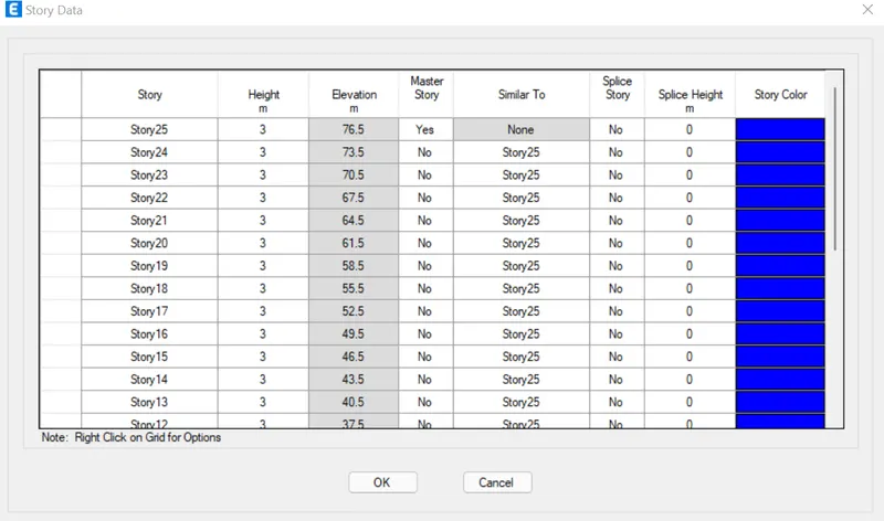
Similarily For Story Dimension Select Custom Story Data--> Edit Custom Story Data-->Click Ok.
Click Ok again
2. Define and Assigning the Material Properties and Frame Section
Material Define For Concrete
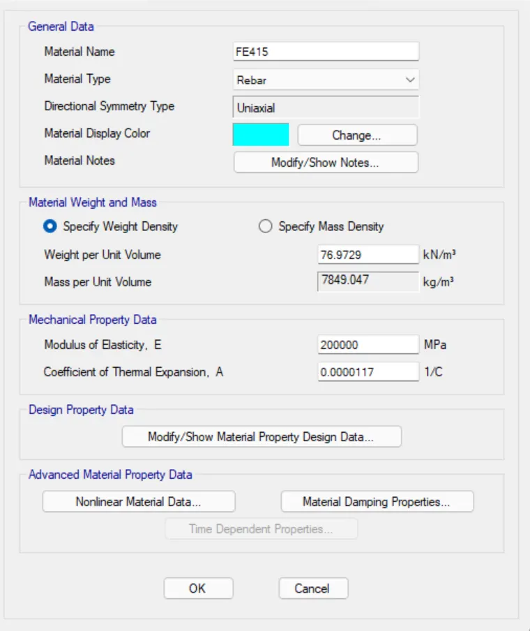
Material Define For Steel Rebars
Define Frame Section Property For Beams
Define Frame Section property For Columns
Define Frame Section property For Slab
After Defining the materials and section properties Assign it by using Quick Tool bar Options
3. Define Load and Load combination as per the requirement
The Live Load on slabs are assigned in the form of shell load of 3 kN/m^2 and the wall loads are assigned in the form of frame loads having 10kN/m for all the floor including roof parapet.
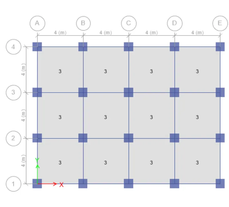
Slab Loads
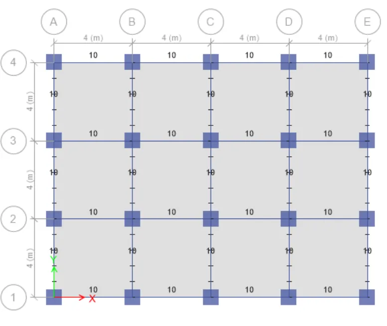
Frame Loads
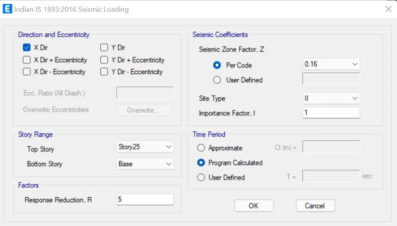
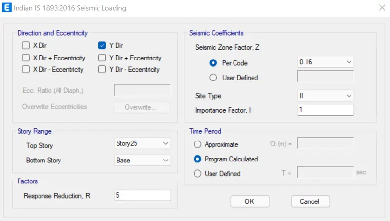
The above said loads were Gravity Load in addition to this Lateral Loads like seismic loads EQX+ and EQY+ were included in this structure. Therefore we need to define in EQx+ and EQy+ on Define Load Pattern
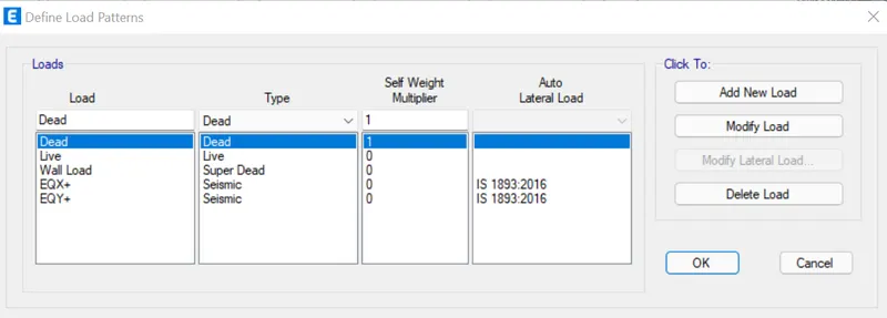
The EQx+ and EQy+ seismic factors were referred through IS 1893-2016
For Soil Type II and Zone III
Similarly for the EQy+
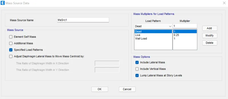
In addition to this seismic load calculation to carried out by Mass source Define
According to IS 1893-2016 the percentage of live load to be considered in seismic weight.
Therefore Refer Table 10 of IS 1893-2016 the Live Load (Imposed Load) on the floor is upto 3kN/m^2 then the percentage of Live load is 25 %
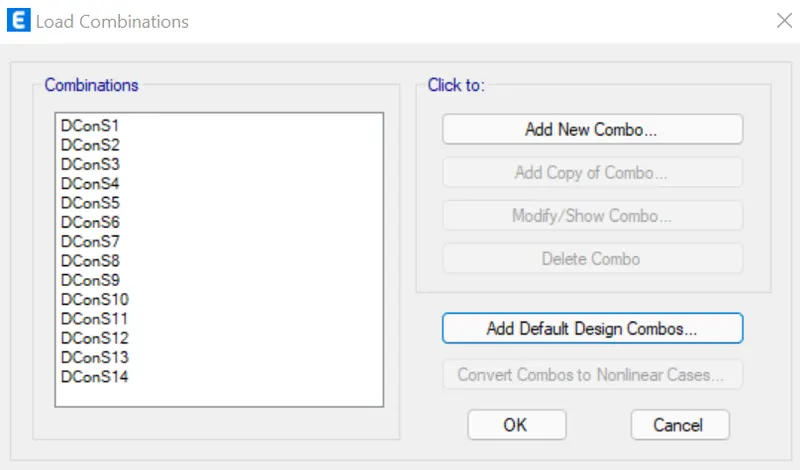
Once all the loads are assigned Define Load Combinations on ETABS
Define and Assign Diaphragm. Diaphragm which transmits lateral loads to the vertical structural elements

4. Analyze the Structure
Once all the Loads and Load Combinations were assigned then go for check model before analysis.
The check model will give warning about the structure as we get any mistakes on modelling.
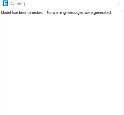
If No warnings then we can analyze the structure.
Once Analyse the following parameters to be checked from result Output
The results were taken through Display---> Show Tables---> In Analysis Results---> Expand Structural Output---> Modal Information. On this Modal Information we get the necessary values as required
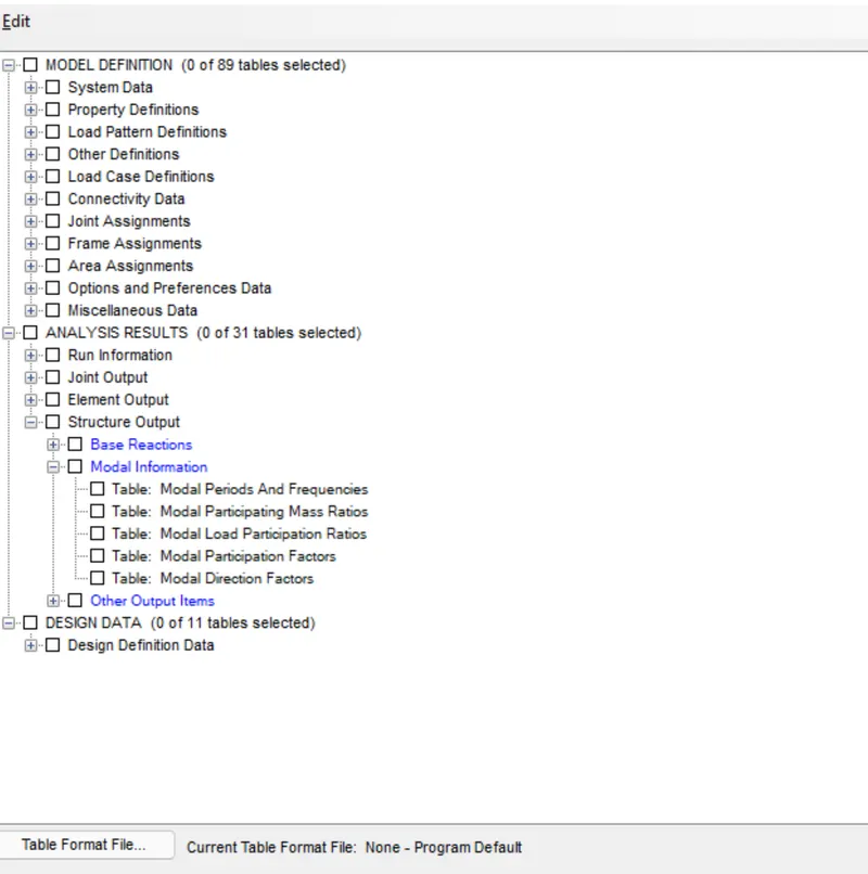
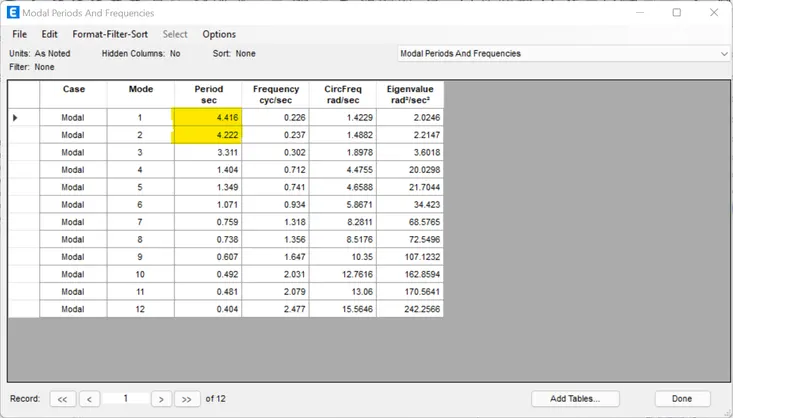
(A) In order to Find the Fundamental Natural Period of Vibration in X and Y Direction
On Modal Information Click Modal Periods and Frequenices we get the
`T_(x_1)=4.416 sec and T_(y_1) = 4.222sec`
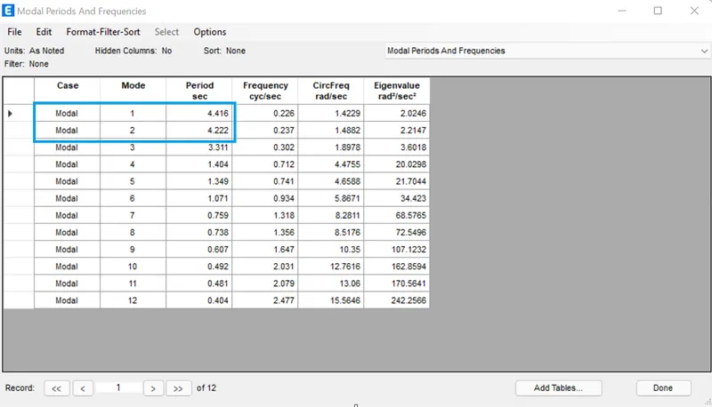
The Mode 1 value is the fundamental natural period of vibration along x direction and mode 2 along y direction
(B) Check for Torsional Irregularity
According to IS 1893-2016 (1) of Table 5
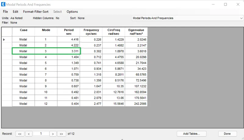
The natural period corresponding to the fundamental torsional mode of oscillation must be less than those of the first two translational mode of oscillation along the each principal plan directions.
From Tables of Etabs we Can seen the value on Mode 3 is 3.311 which is less than that of the first two modes of natural vibration therefore it satisied the condition.
(C) Check for Vertical Irregularity
According to IS 1893-2016(1) Table 6 for Seismic Zone III
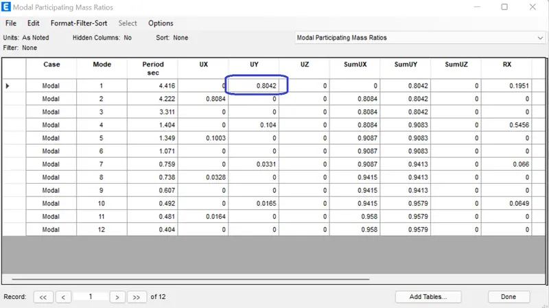
(i) The first three mode contribute together atleast 65% of mass participation factor in each principal plan direction.
From Etabs Result we came to conclude that the mass participation factor value for mode 1 is 0.8042 which means 80% of value is achieved during first mode itself there fore it satisfies the condition
(ii) The fundamental natural periods of the building in the two principal plan directions away from each other atleast 10% of larger value.
From Tables on ETabs File the mode 1 natural period is 4.416 then as per the condition mode 2 natural period will be 4.416 x 0.90 = 3.97 but the value we get etabs as 4.216 therefore it not satisfied.
(D) Check for Inter- Storey Drift
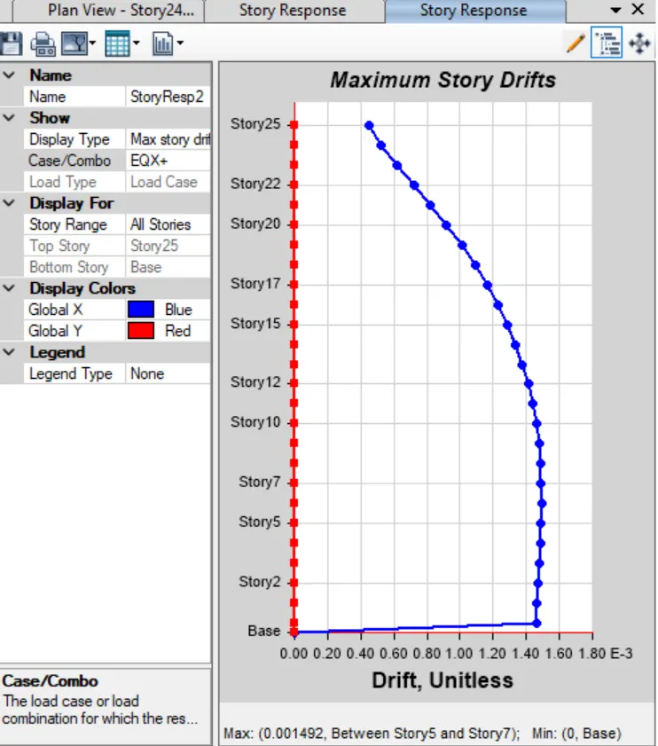
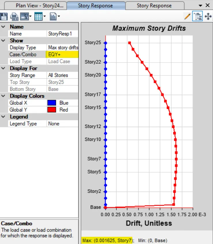
According to IS 1893-2016(1) Cl 7.11.1.1 Storey Drift if any storey shall not exceed 0.004 times the storey height,under the action of design base of shear with no load factor
From Etabs Results ---> The story Response Plot we get the value around 1.40e-3 to 1.60e-3 for EQX+
1.50e-3 to 1.75 e-3 on EQY+ Maximum of 0.001625 on 7th floor which is less than that of 0.004 times of storey height therefore it satisfies the condition.
Conclusion
The G+25 RCC Building were analyzed using Etabs. From the result we can conclude the fundamental natural period of vibration along X and Y directions were satisfied. The torsional irregularities were less than that of natural time period therefore it also satisfies the limit.
The Storey drift analysis were also satisfied as per IS 1893-2016 requirements
The Vertical Irregularities contributes above the value of modal participation factor above than 65% but it not satisfies the condition of fundamental natural periods of the building in the two principal plan directions away from each other atleast 10% of larger value.