Modelling of 25 storey building with the specified properties using ETABS
Aim: to model and analyse a 25 storey building with given specifications and to cross check the parameters as per IS 1893 provisions.
Introduction: ETABS offers is the recognition of story levels, allowing for the input of building data in a logical and convenient manner. You can define your models on a floor-by-floor, story-by-story basis, analogous to the way a designer works when laying out building drawings. ETABS dynamic analysis capabilities include the calculation of vibration modes using Ritz or eigen vectors, response-spectrum analysis, and time-history analysis for both linear and nonlinear behaviour.
Procedure:
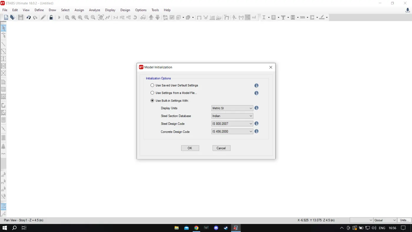
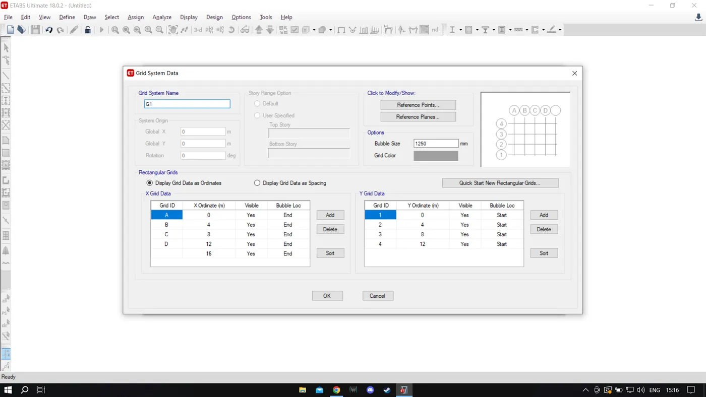
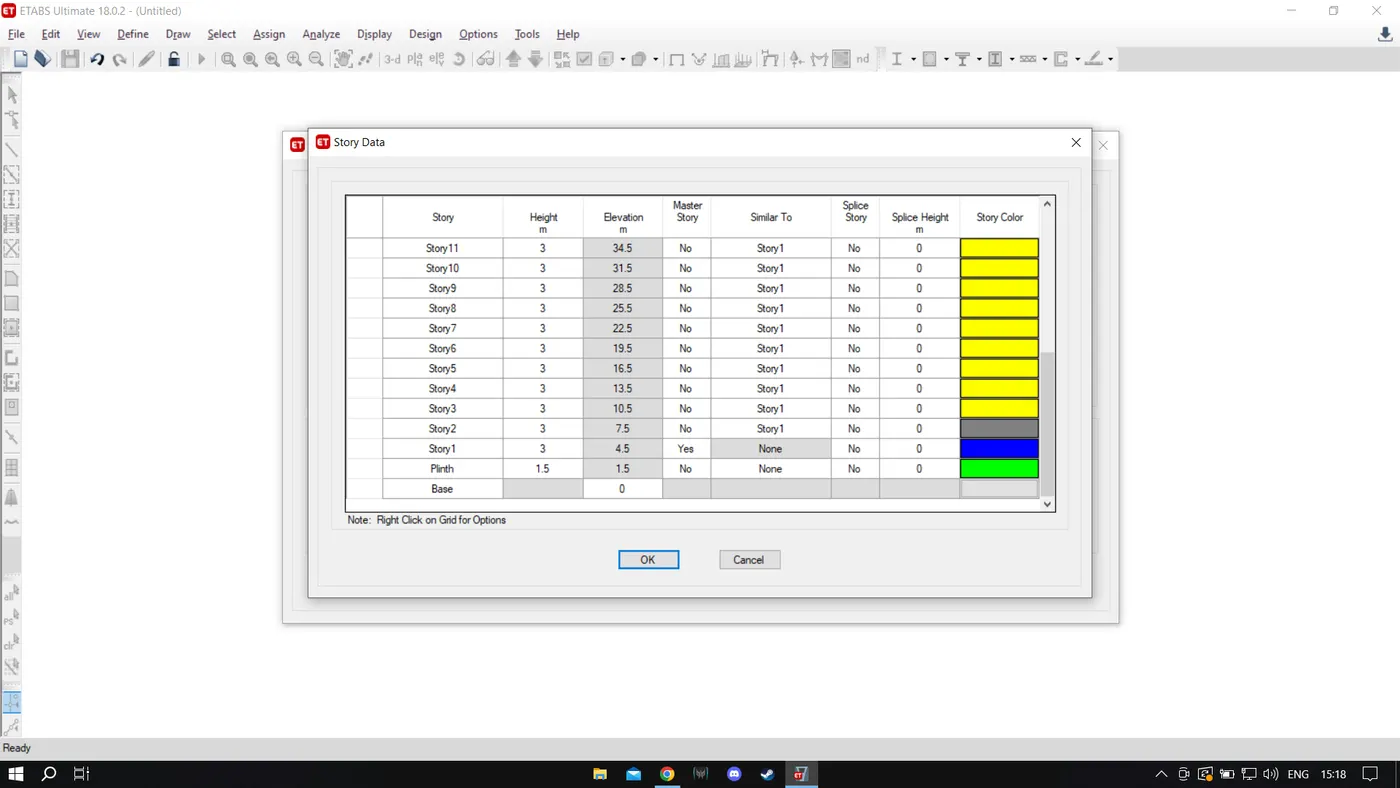
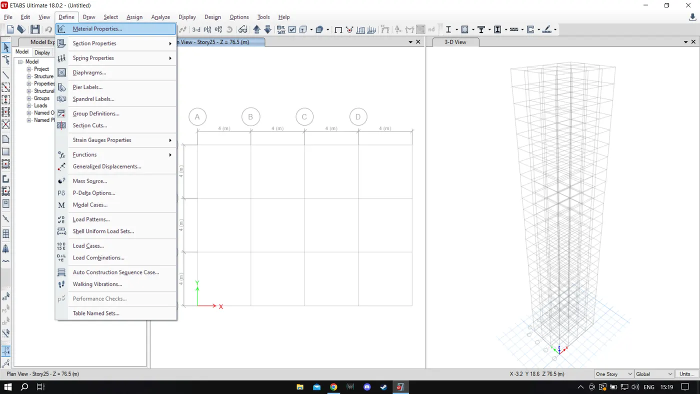
- Select material properties under the define tab.
- Define the materials of concrete M30 grade and steel of as 415 grade.
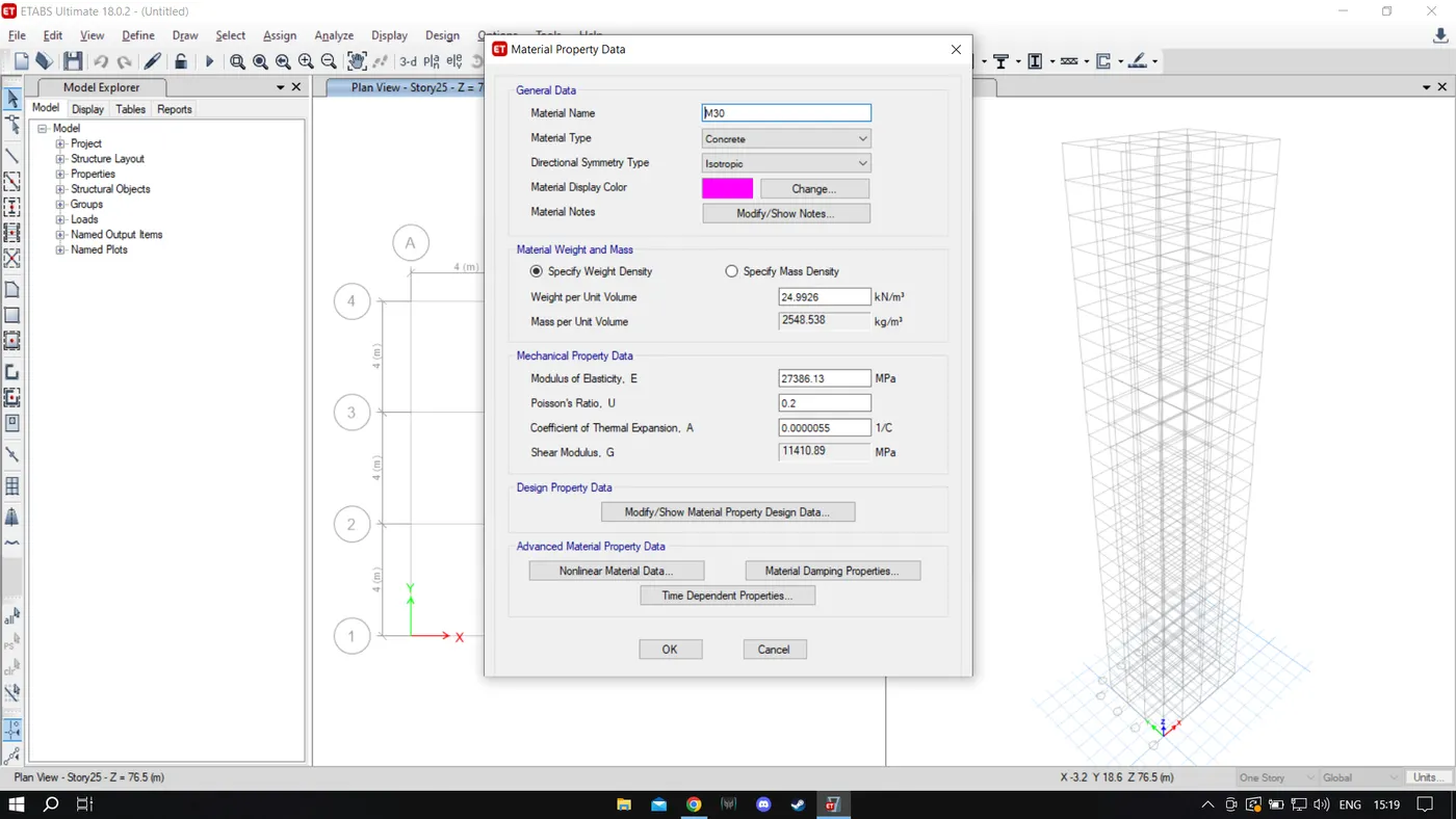
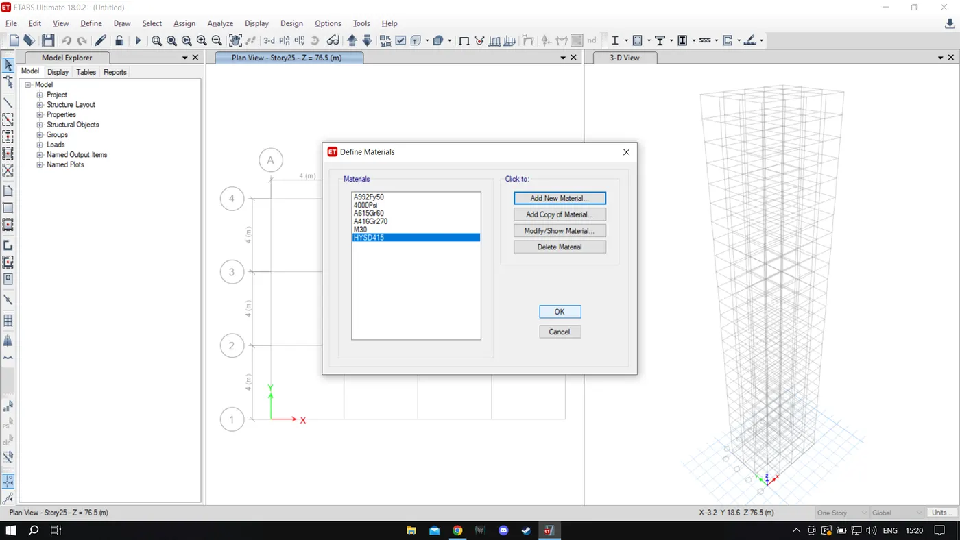
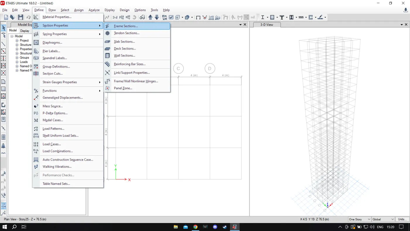
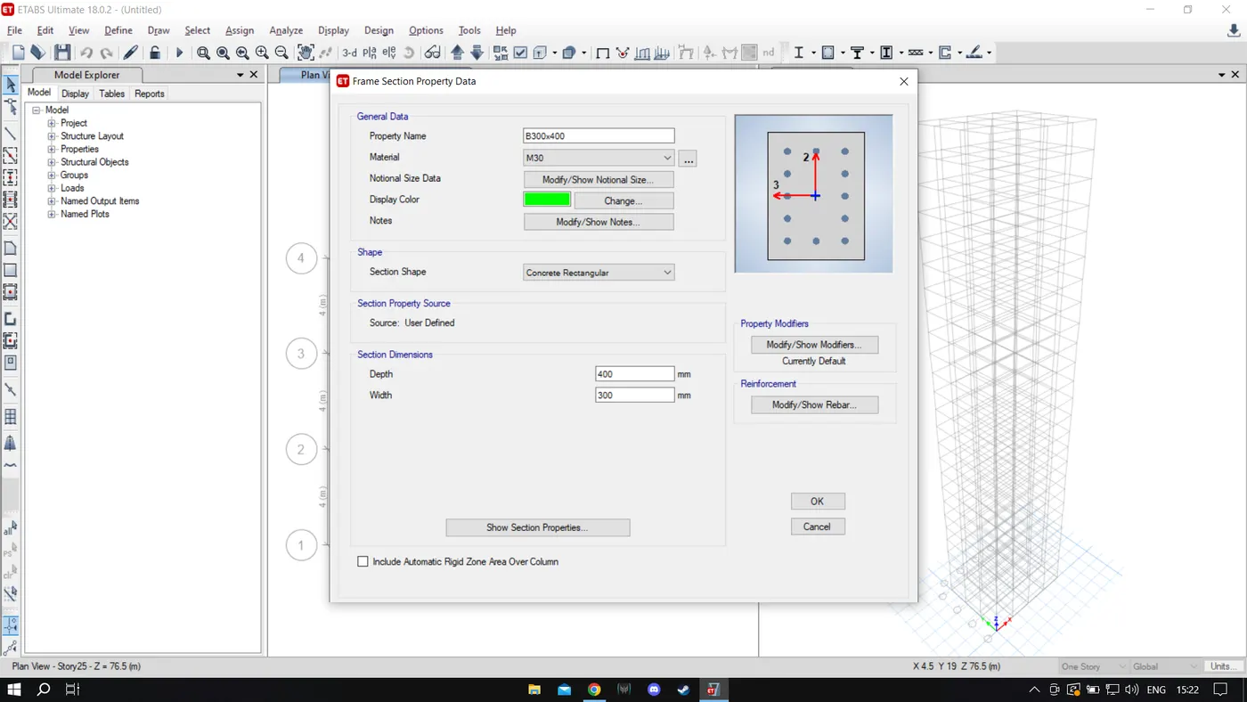
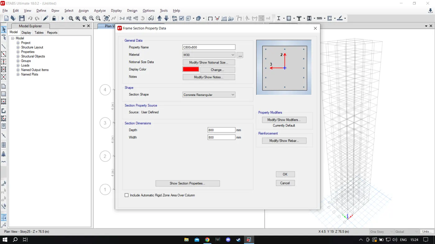
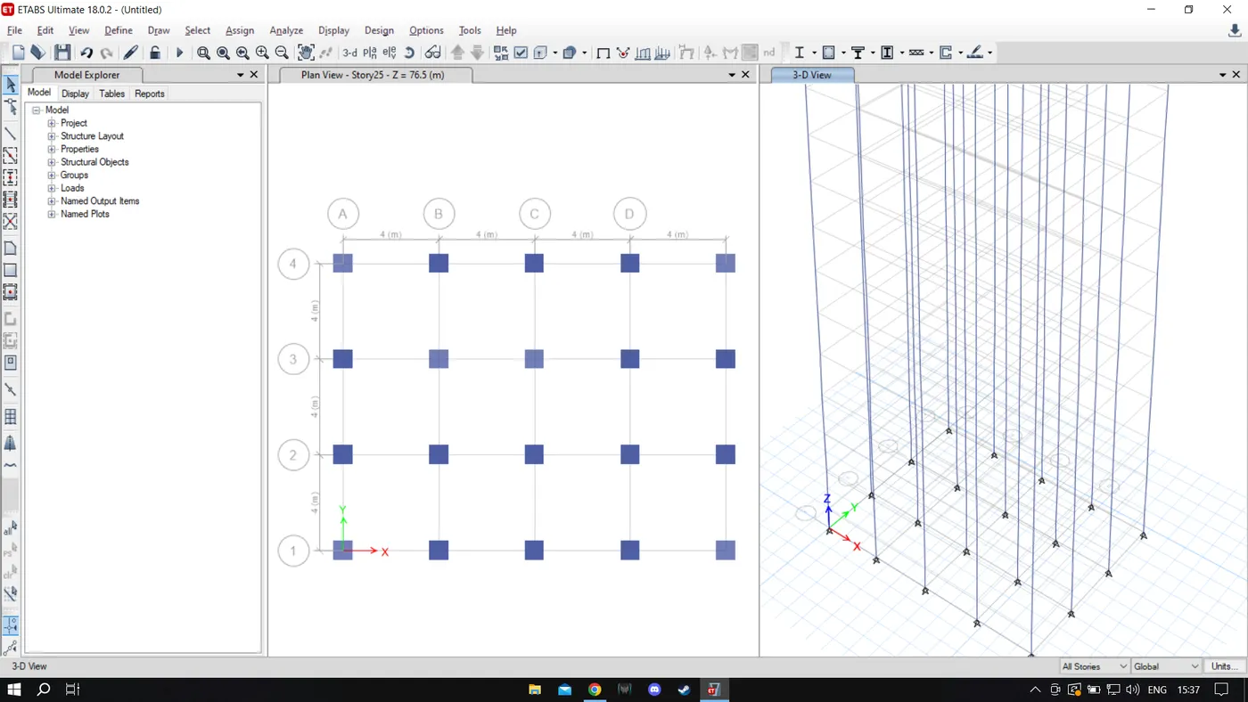
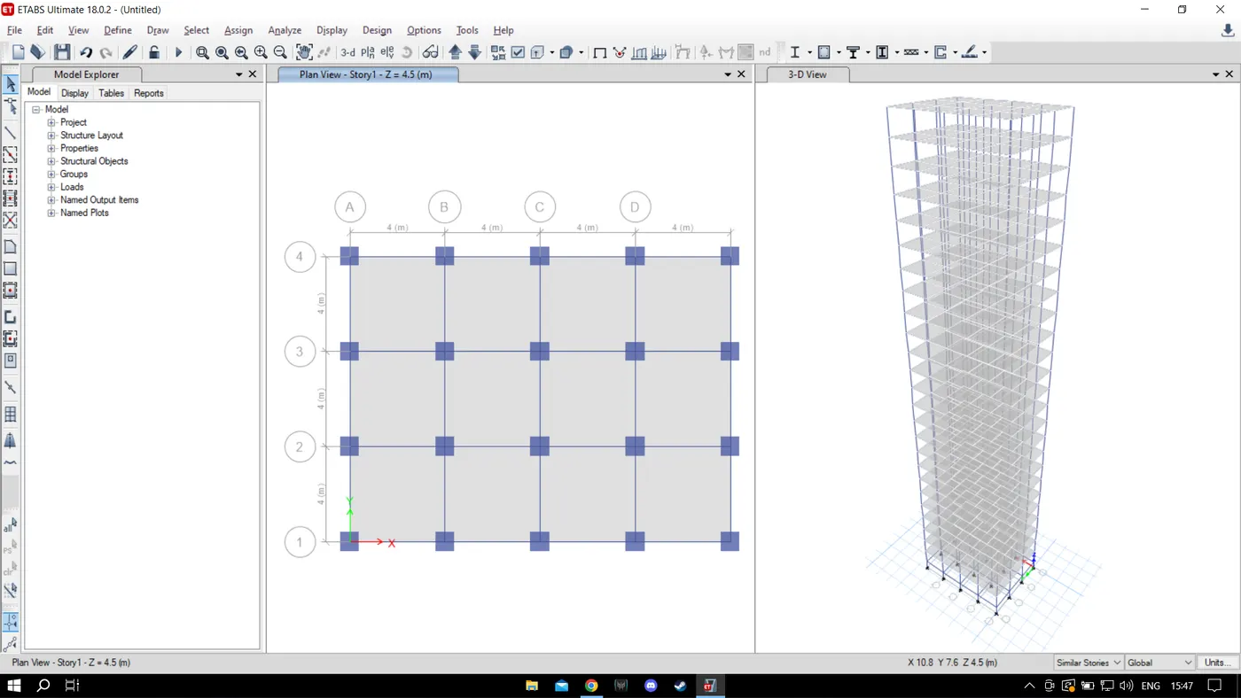
- Now draw a column of size 800X800mm at the intersection of the horizontal and vertical grid and beams with quick draw tool keeping all stories on.
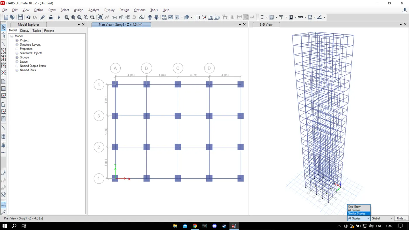
- Beams drawn using quick draw beam tool keeping all the stories on.
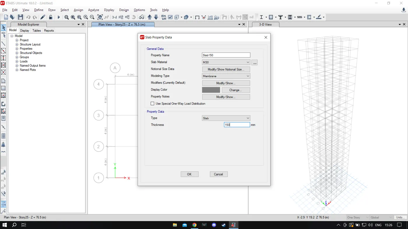
- Using the quick draw floors option, all the slabs have been modelled keeping "similar stories" ON.
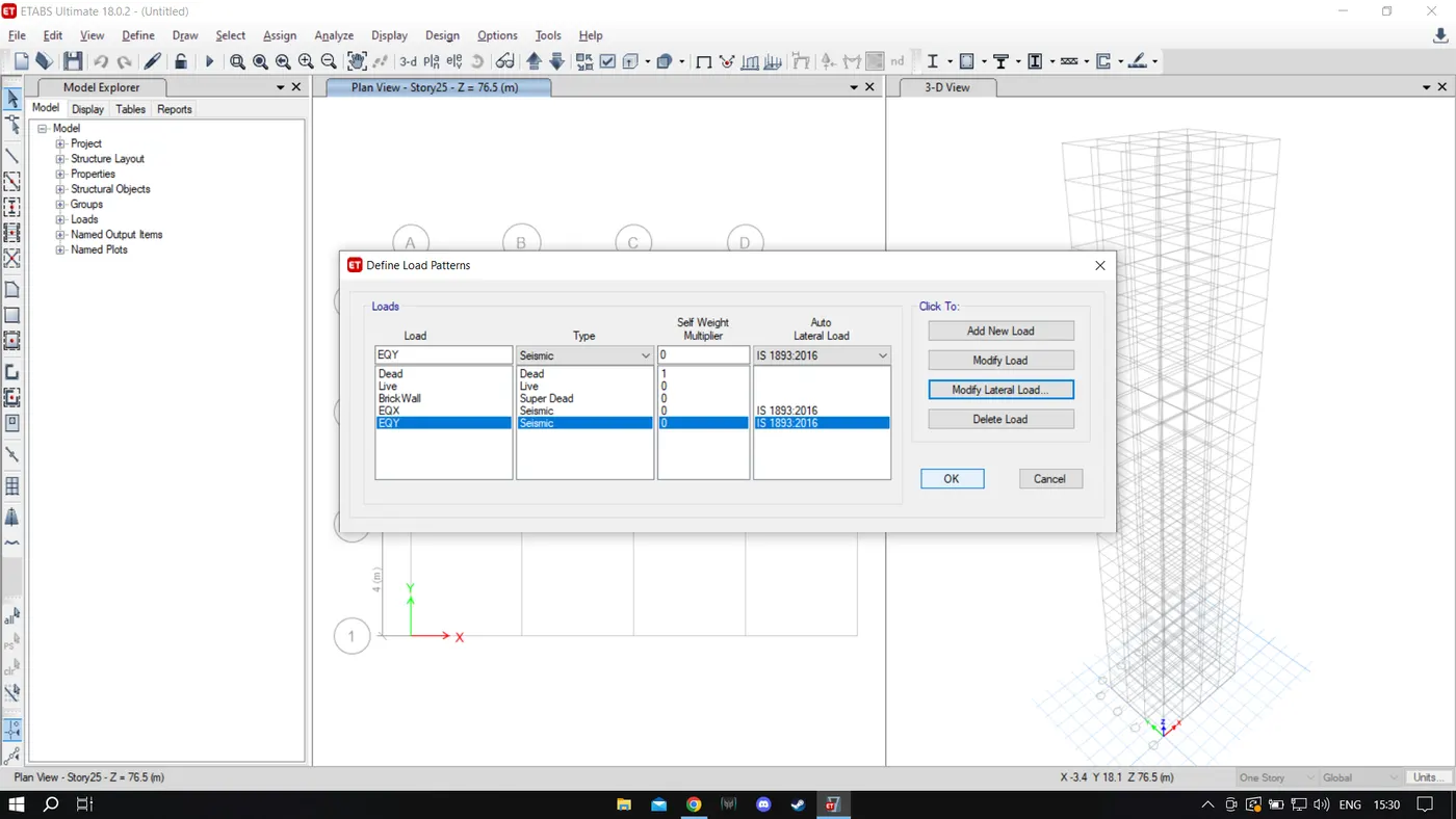
- Now define the load patterns: click on the define ta and click on load patterns.
- Define the loads like dead load, live load, brick load, earth quake load in x direction and same loads in the Y direction also. Mention IS codes of respective loads.
- Click on modify lateral load, set range from base to 25th storey and seismic zone factor as 0.16 (zone 3), importance factor 1, site-type II , Response Reduction Factor as 5 and time period program calculated.
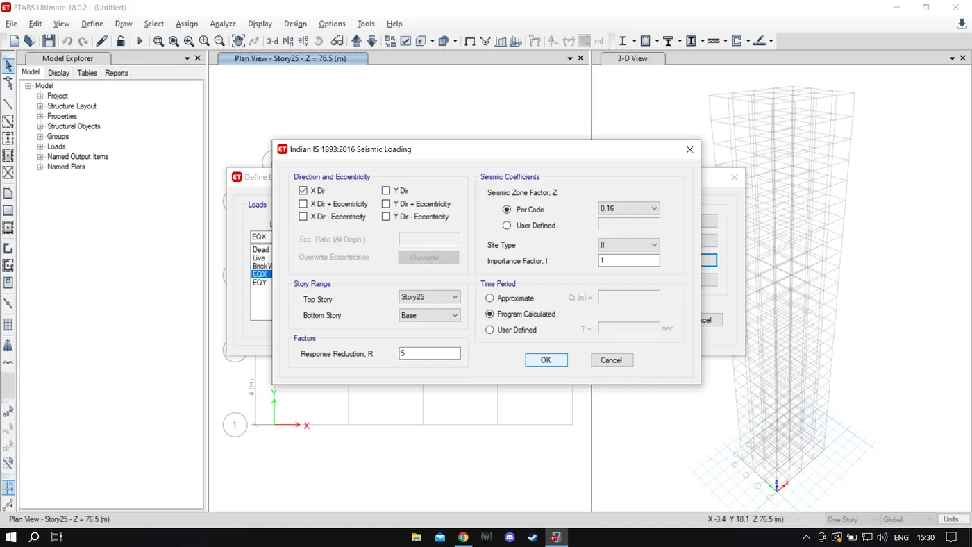
- Do the same for all the earthquake loads.
- Assign the loads and select similar stories.
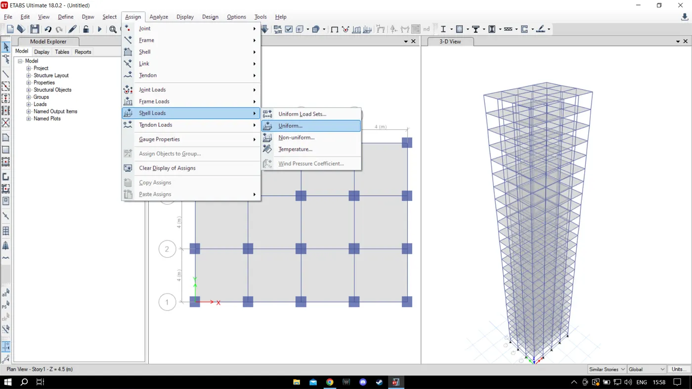
- Click on shell load under the assign tab.
- Click on live load and give value as 3kn/m^2.
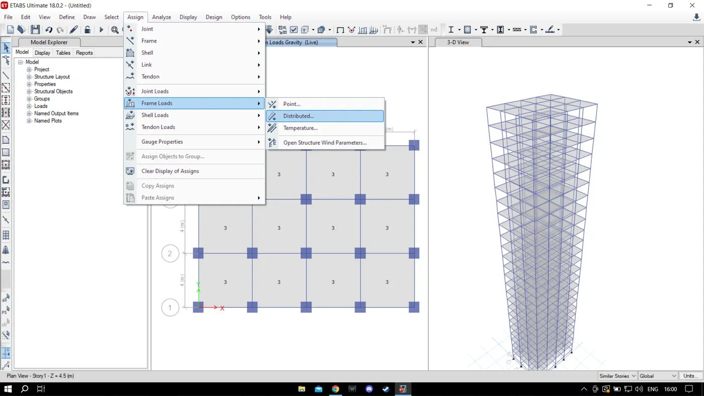
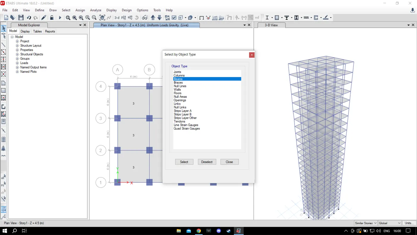
- For that select all the beams from select object type beams.
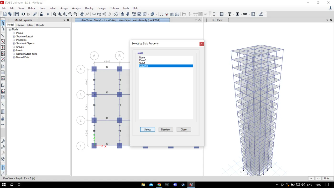
- Go to the frame load and click on the distributed load and enter the value as 10 Kn/m^2.
- Define the load cases:
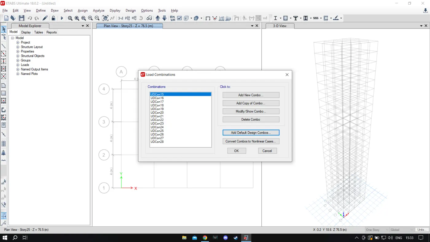
- Click on the load combinations.
- Click on the add default design combos.
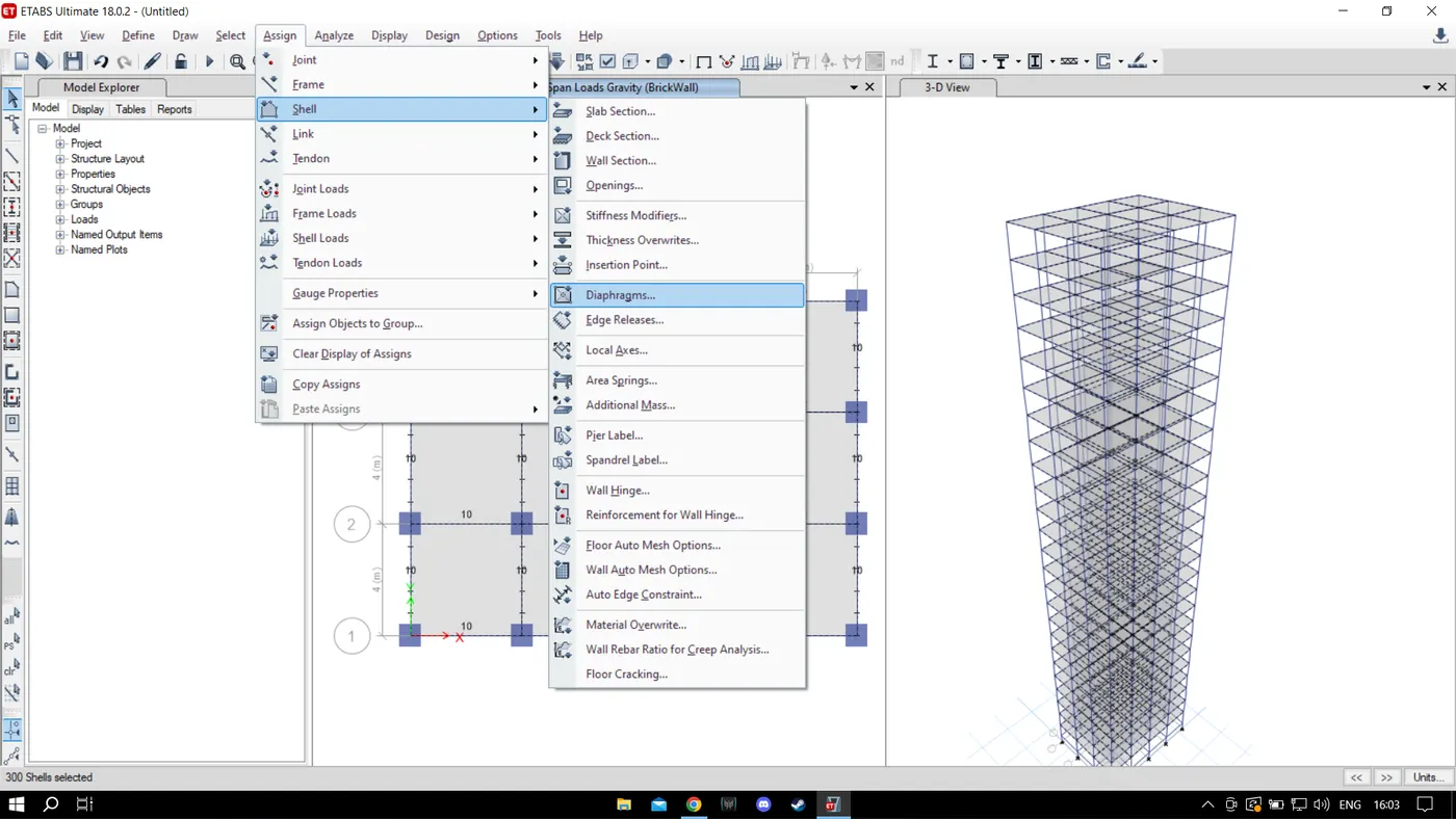
- Now create the diaphragm by going to the assign tab then shell and select diaphragms.
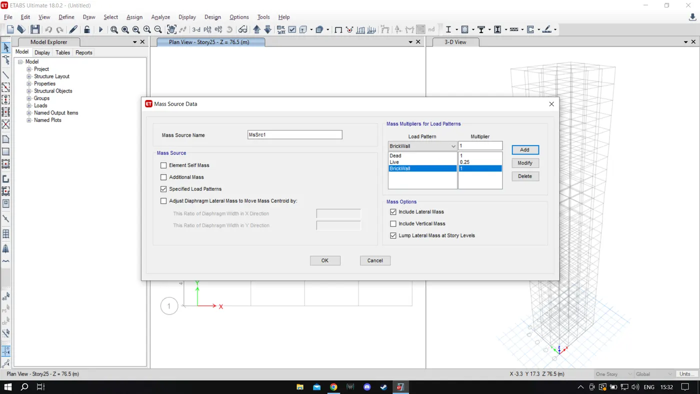
- We add mass source
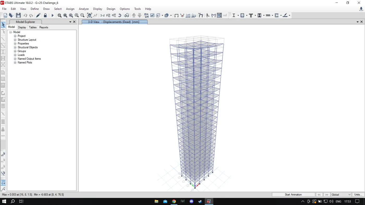
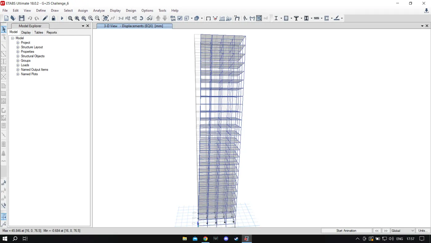
Using analyse >run analysis ,the model is analysed and deflection patterns, BMD/SFD patterns are cross checked logically .It is understood that the worked model provides reliable results.
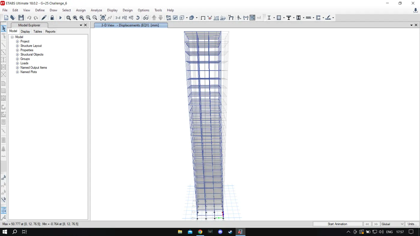
Results:
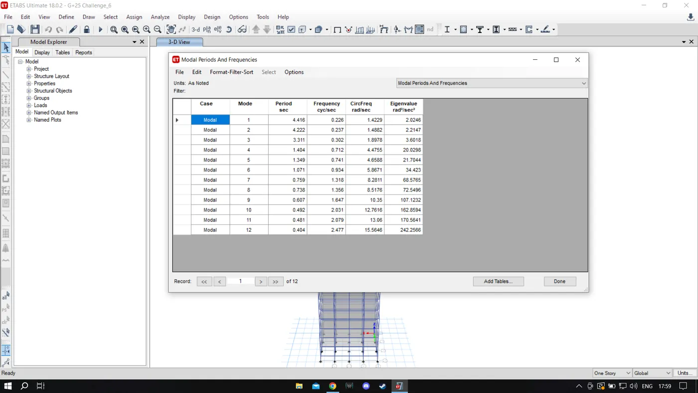
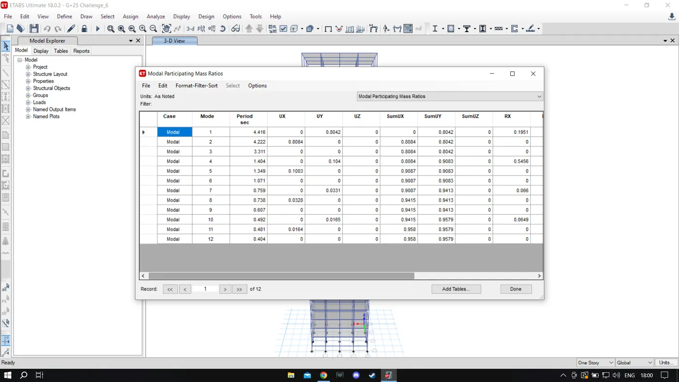
- Now click on Display>show tables>Analysis results>Structure output>Modal information>modal periods and frequencies.
- The time periods for fundamental mode-1Y direction and fundamental Mode -1X direction are noted from the table and are as follows:
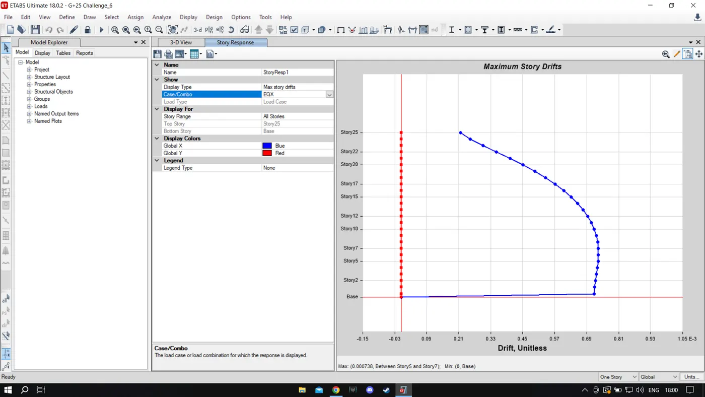
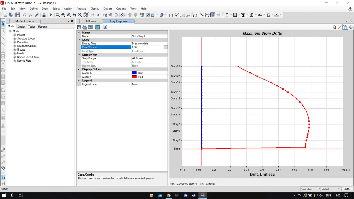
- So as per the clause 7.11.1.1,the maximum inter storey drift is to 0.004 for each storey height .
Conclusion:
The modelling is completed and analysed in ETABS .The results are within given ranges.