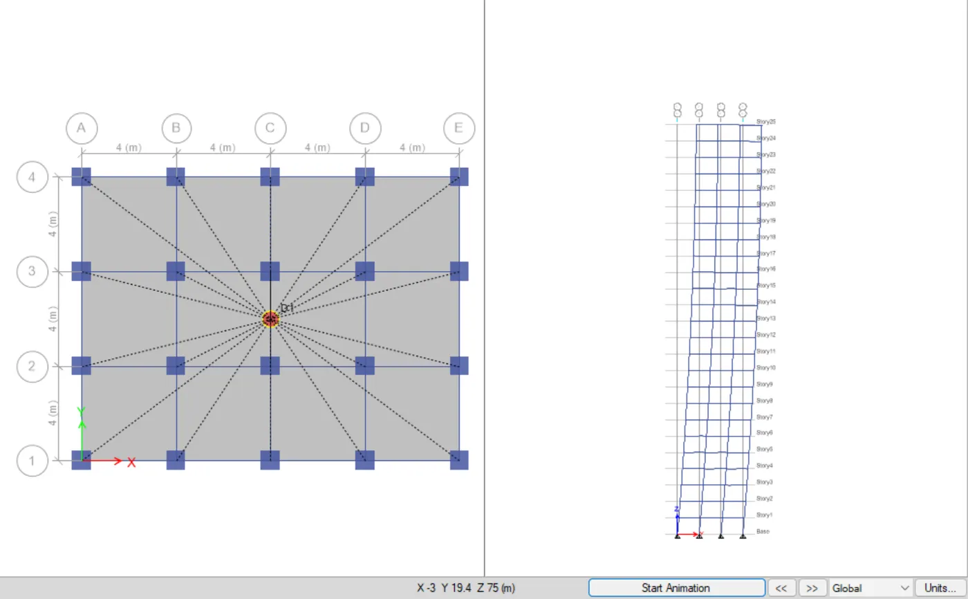
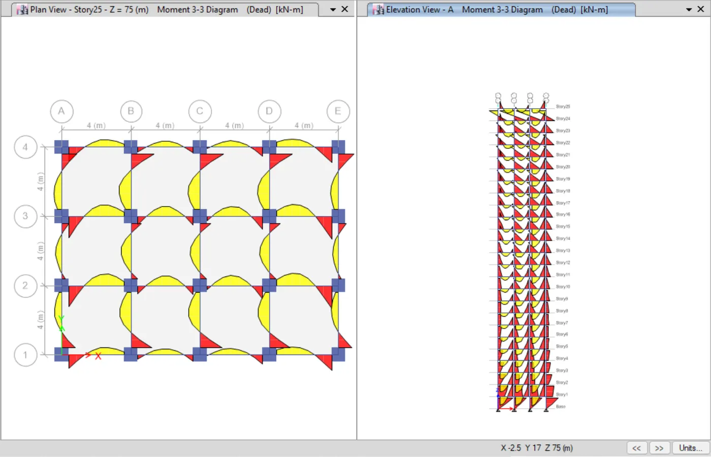
Modelling of 25 storey building with the specified properties using ETABS
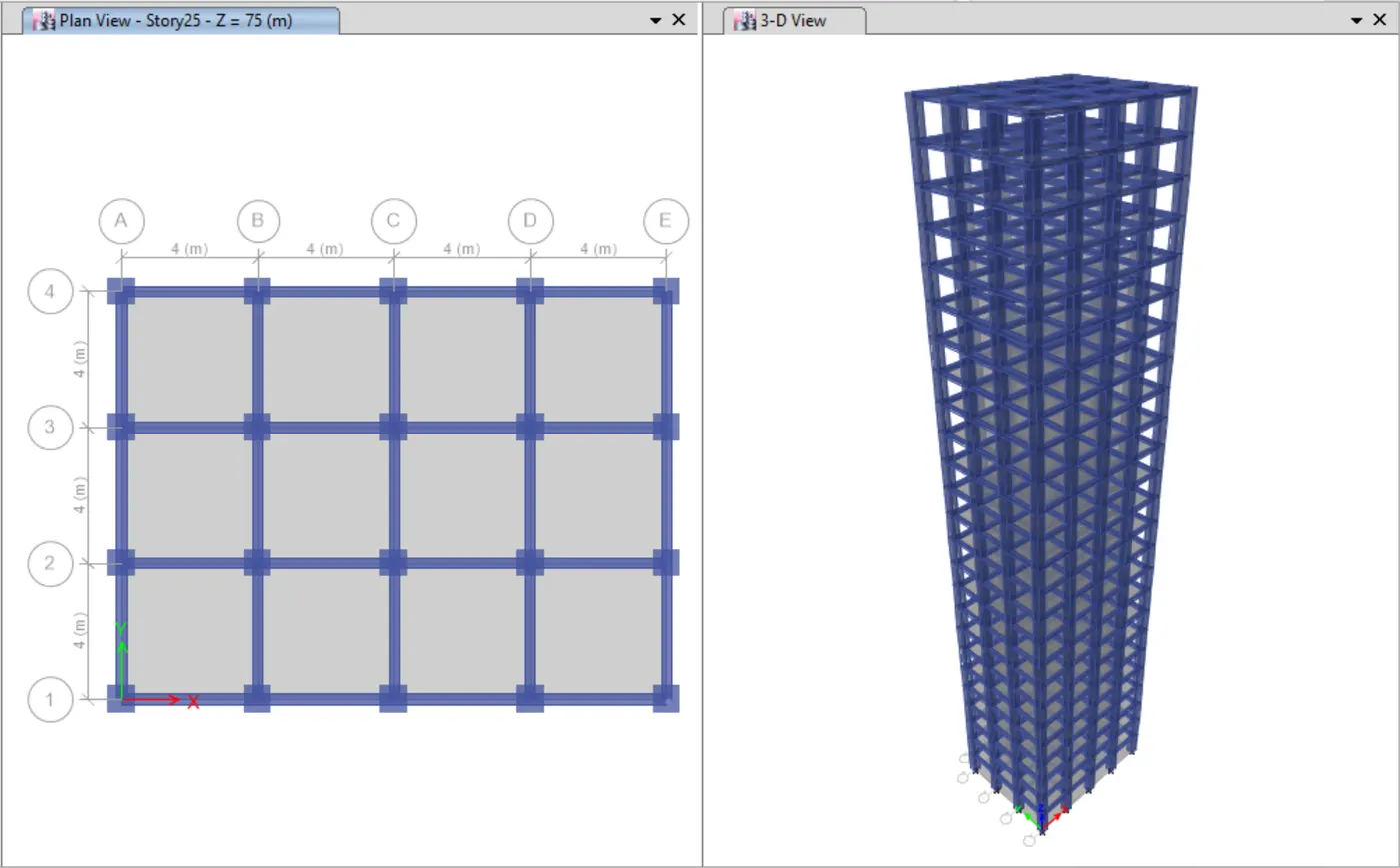
Model a 25 storey building on ETABS with structural properties as specified below. Ground floor or plinth floor level can be taken at a height of 1.5 metres from the base. Each of the successive 25 storeys has a storey height of 3 metres.
Structural Element Sizes
- Beams : 300 × 400 mm
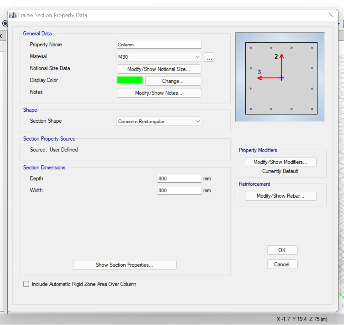
- Columns : 800 × 800 mm
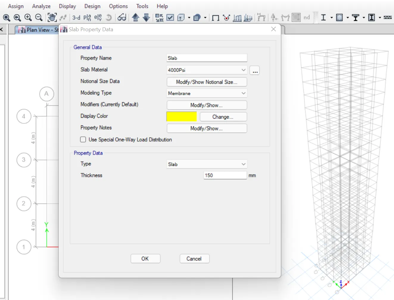
- Slab : 150 mm thick
Material Properties
- Grade of Concrete : M30
- Grade of Steel Reinforcement Bars : Fe 415
Loading
- Dead Load on beams from infill wall : 10 kN/m (Let us assume the same for roof floor in view of parapet)
- Live load on floor : 3 kN/m2 (Let us assume the same for roof floor)
a) Buildings are assumed to be pinned at the base
b) All columns in all storey are of the same size
c) All beams in all storeys are of the same size
d) Building is located on Soil type-II and in Zone-III. Assume other factors if required.
Ans:
Procedure:
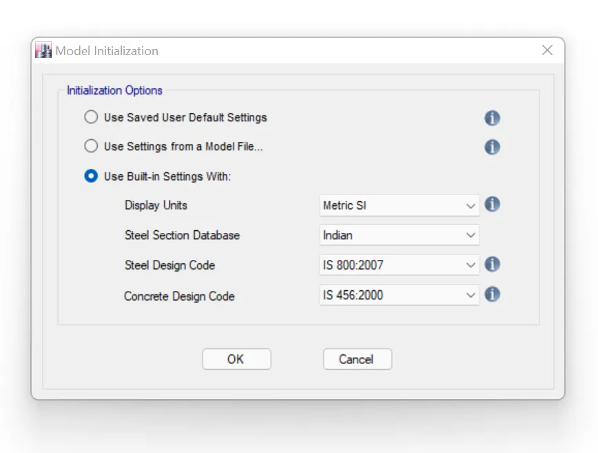
1. Model Initialization:
- Open ETABS software.
- Click "File" -> "New Model".
- In the "Model Initialization" window, set units (e.g., meters, feet) and analysis options (2D or 3D).
2. Define Grid System:
- Go to "Define" -> "Model" -> "Grid Data".
- Choose "Custom Grid Spacing" and click "Edit Grid Data".
- Define the grid layout for the building footprint. This includes the number of bays in each direction and spacing between grids.
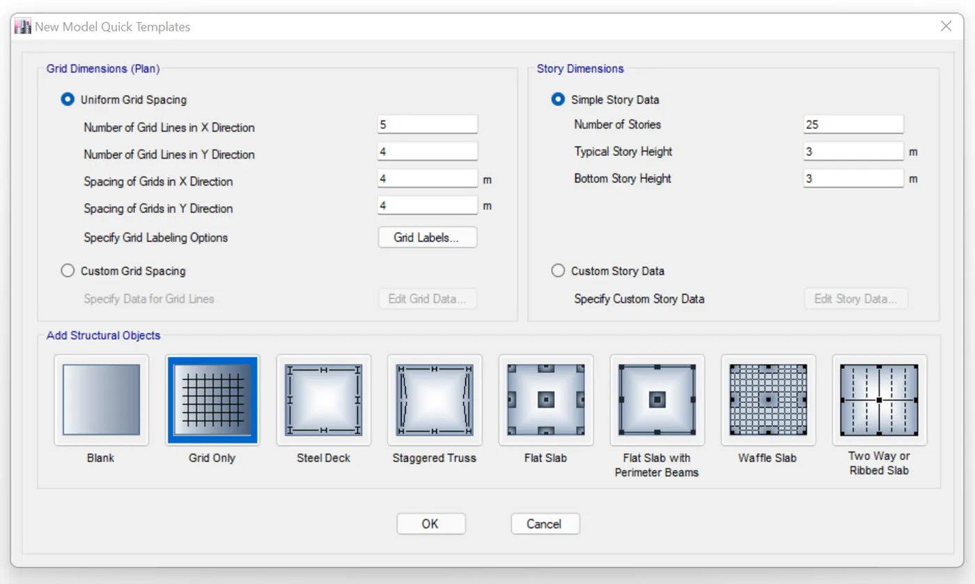
3. Define Story Data:
- Go to "Define" -> "Model" -> "Story Data".
- Choose "Custom Story Data" and click "Edit Story Data".
- Define the story heights for all 25 floors. You can set a master story height and specify variations for other floors.
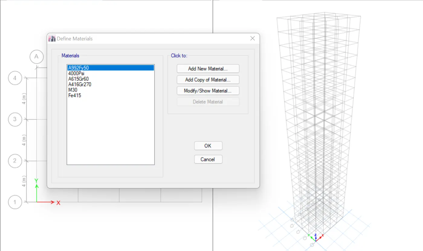
4. Define Materials:
- Go to "Define" -> "Materials".
- Click "Add New Property".
- Specify material properties like concrete or steel, including density, strength, and Poisson's ratio. You can define separate materials for different structural elements (columns, beams, slabs).
5. Define Sections:
- Go to "Define" -> "Section Properties".
- Choose the element type (e.g., beam, column, slab).
- Click "Add New Property" and define the section geometry. This includes dimensions like width, depth, and thickness for beams and columns, or slab thickness.
6. Model Geometry:
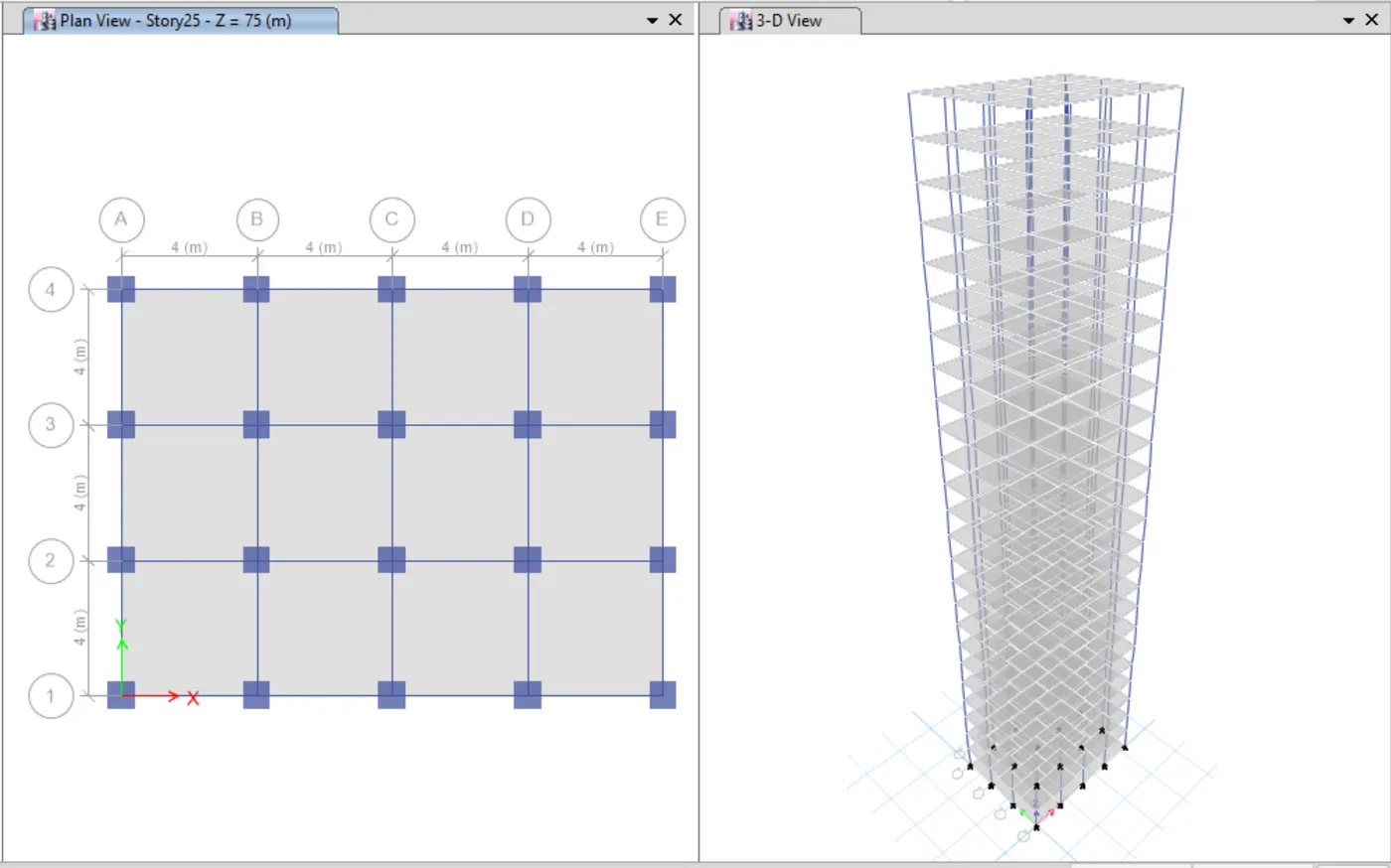
- Use the "Draw" menu to create beams, columns, and slabs.
- Columns: You can use quick draw options or define them by coordinates.
- Beams: Similar to columns, use quick draw or define by connecting grid points.
- Slabs: Define the slab area by selecting the building footprint.
7. Assign Properties:
- Select the beams, columns, and slabs you created.
- In the "Properties" window, assign the corresponding material and section properties defined earlier.
8. Define Loads:
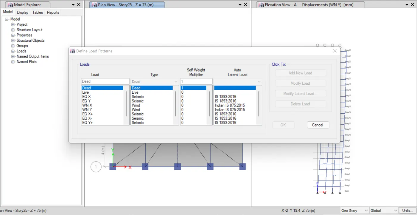
- Go to "Define" -> "Load Patterns".
- Define load patterns for different types of loads (e.g., dead load, live load, wind load, earthquake load). You can specify the load value or use pressure per unit area.
9. Define Load Cases and Combinations:
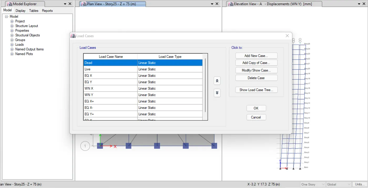
- Go to "Define" -> "Load Cases".
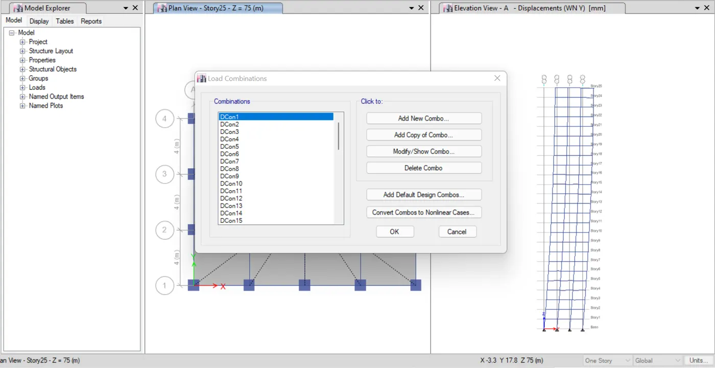
- Create load cases by combining different load patterns (e.g., dead load + live load, all seismic load cases).
10. Analysis and Design (Optional):
- Once the model is complete, you can proceed with structural analysis in ETABS.
- The software can calculate internal forces, deflections, and assess member capacity based on the defined materials, sections, and loads.