Modelling of 25 storey building with the specified properties using ETABS
AIM:
Check the building response for seismic force in both X and Y direction by analysis and model the 25 building storey building with specified story inn ETABS.
PROCEDURE:
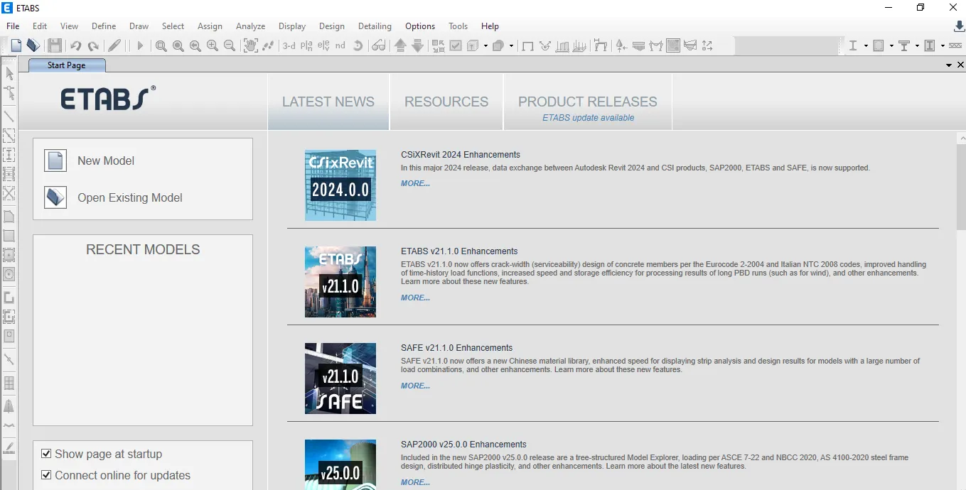
Open the ETABS software.
Then click on the new model option which is at left side of the sreen.
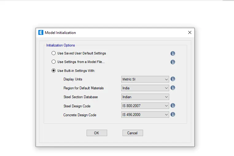
Then select the use built in setting with set the unit as metric database as indian steel code book as Is 800-2007 and concrete design code as Is 456-2000
Then click on ok.
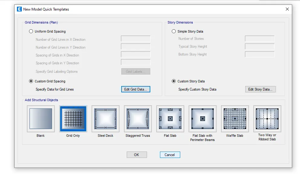
After completion of model initialization then new model quick template dialouge box open.
Select the custom grid spacing and custom storey data and then edit accordingly.
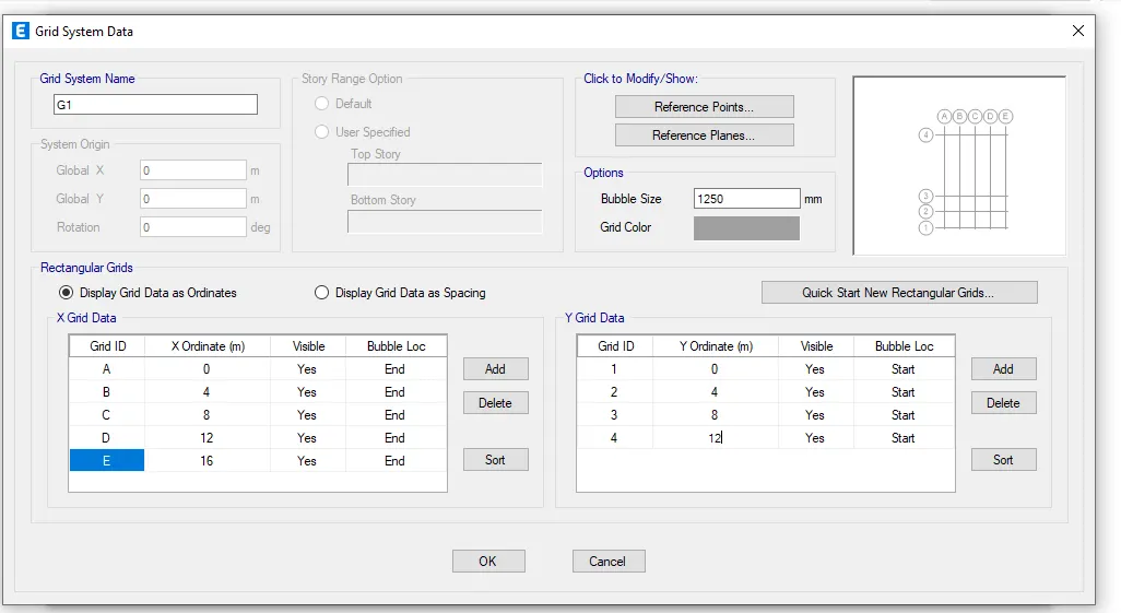
Mention the grid spacing for the both X and Y direction.
The spacing of storey are 4m offset.
Then click ok.
After editing the grid spacing then select the storey data then edit that.
click on the edit storey data to edit the stories.
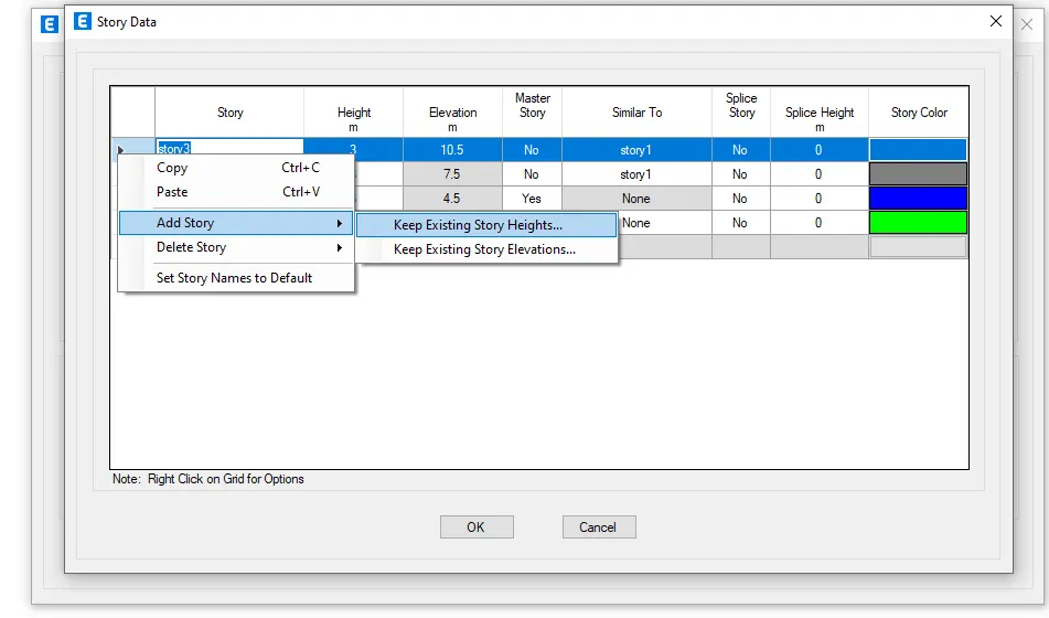
click on the storey 2 then click on the right buttom of your mouse.
Then click on the add storey Then click on the keep existing storey heights.
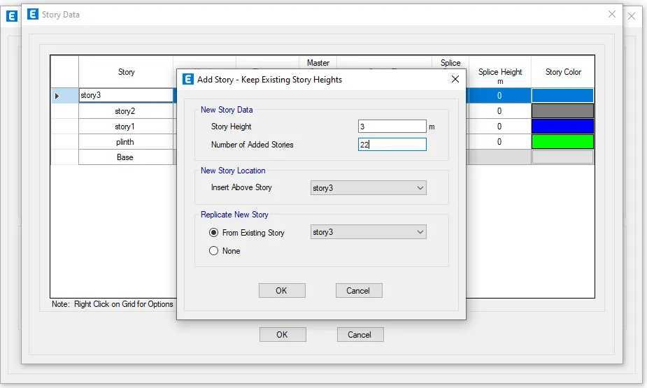
After that add storey dialouge box open.
Then change the number as 22 because we require 25 number of stories here 2 stories are already assigned. then click on ok.
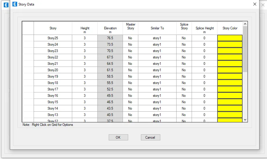
Change the story 3 to 25 as a similar storey.
Then click on ok.
Here there are 25 stories for the builing.
Height of the building should be 3M
Stories in the table are base plinth storey 1 to storey 25
Make the storey 1 as a master storey and make the storey from 2 to 25 as a similar to.
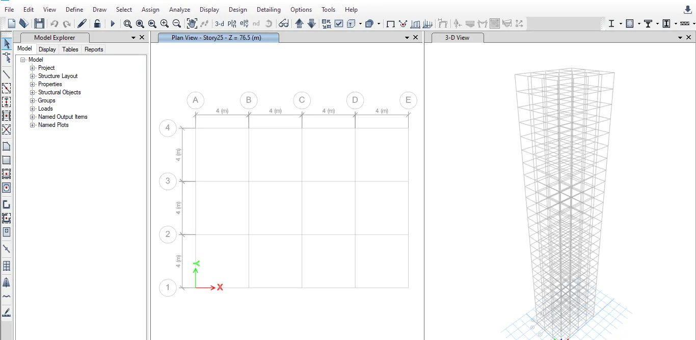
After completing all the grid line and storey data. Then click ok.
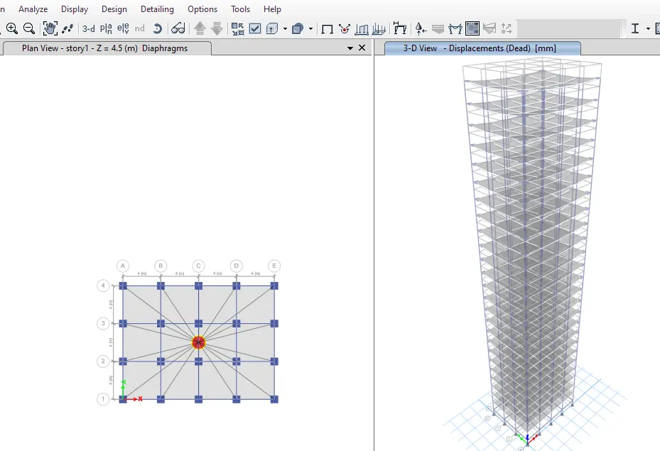
This is the how the structure looks like after completing all the information.
Here the plan view and 3D view are shown in screen.
After completing all the setting define the materials and define the section for the column beams and slab.
click on the define and select the material properties.
click on the new material to create a new material.
select the required properties of the material.
region as india material type as concrete standared as indian grade as M-30.then click ok.
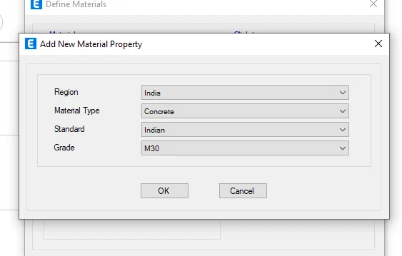
Click on the new material to create a new material.
Select the required properties of the material.
region as india material type as rebars standare as indian grade as HYSD grade 415.then click ok.
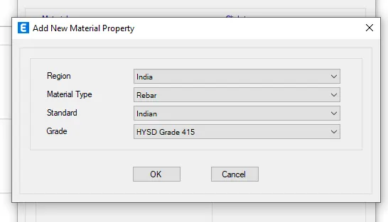
To define a section properties.
Click on the define then click on the section properties Then select on the frame section.
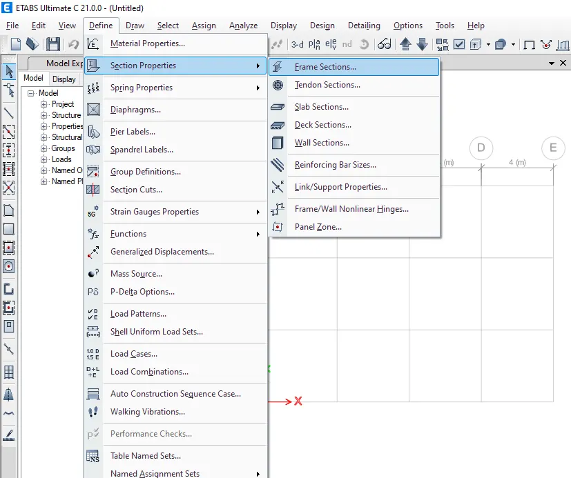
After selecting the frame section.
click on the add new property to create a new frame section.
Select the rectangular concrete for the beam then click on ok.
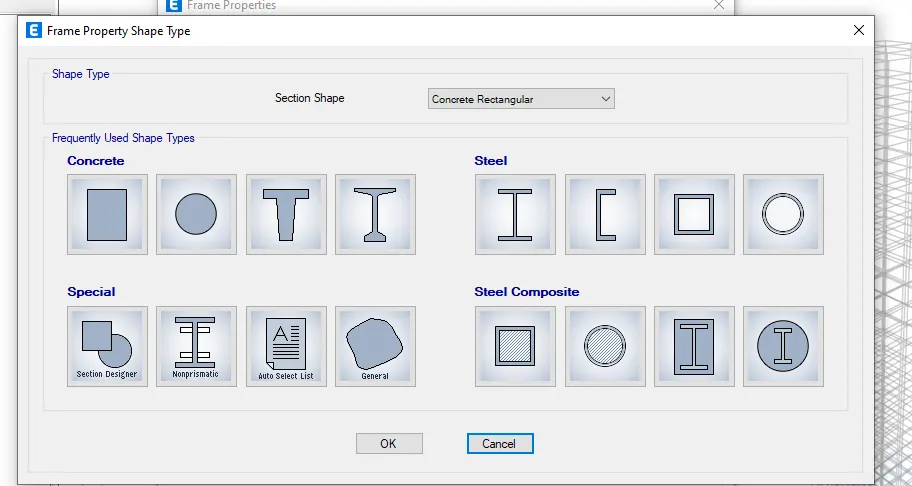
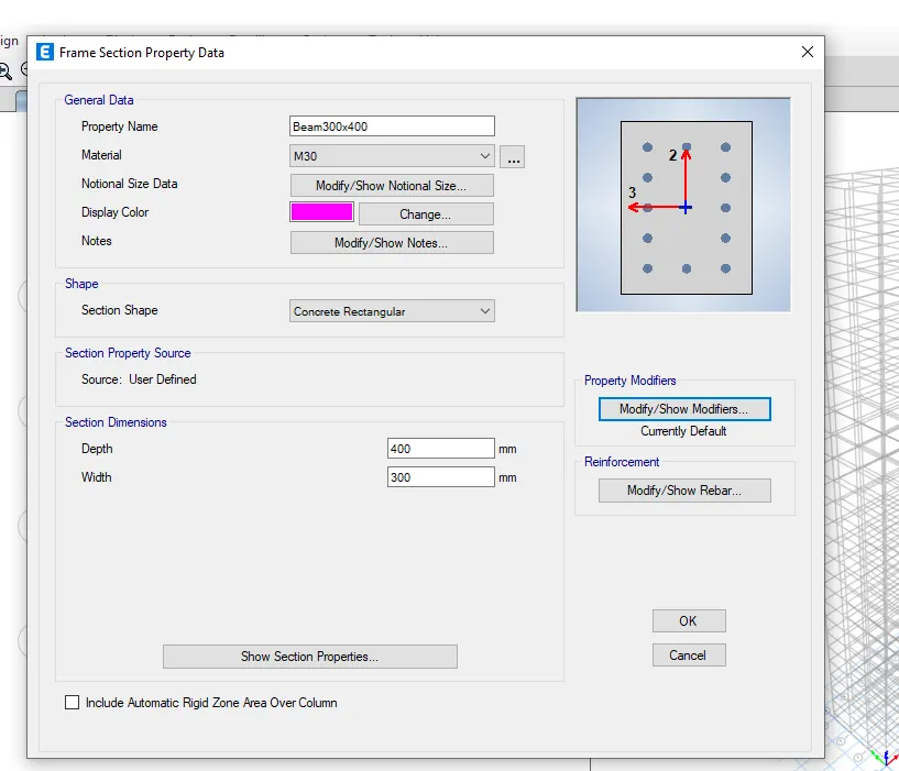
After clicking on ok then frame section property data dialouge box open
Change the property name as beam 300x400 change the material as M-30 change the dimension.
click on the modify/show Rebar to get more.
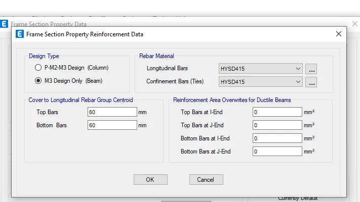
After opening the modify shoe rebars then this dialouge box open.
select the M3 desig only(beam)
Then change the longitudinal and confinment bar as Hysd 415 then click ok.
Select the frame section.
click on the add new property to create a new frame section.
Select the rectangular concrete for the column Then click on ok.
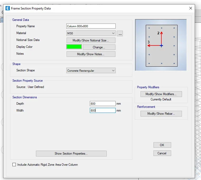
After clicking on ok then frame section property data dialouge box open.
change the property name as column 800x800 change the material as M-30 change the dimension.
click on the modify/shown rebars to get more.
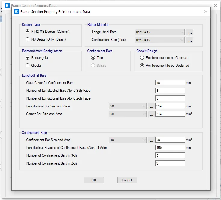
After opening the modify/show rebars then this dialouge box opens.
select the P-M2-M3 design(column)
Then change the longitudinal and confinement bars as HYSD 415 then click ok.
To create a slab.
Click on the define Then select the section properties then click on slab section.
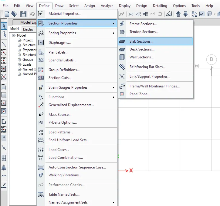
After selecting slab section the slab properties dialouge box opens.
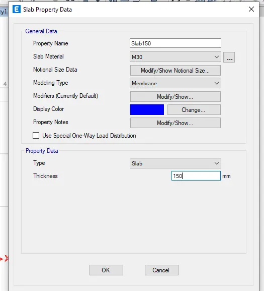
Then click on the modify show properties to change the properties.
Change the property name as slab 150,change the slab material as M-30 and change the slab thickness.then click ok.
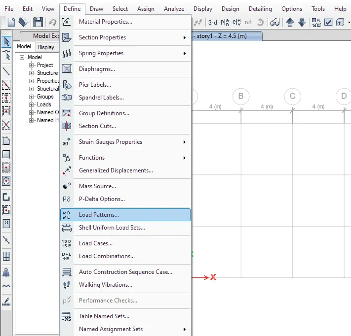
To define the load pattern.
Click on the define Thenn click on the load pattern.
Add the loa patterns.
Dead load, live load wall load,seismic load in both x and Y direction.
Mention the code book for the seismic load.
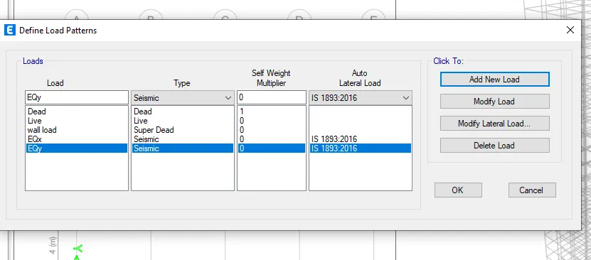
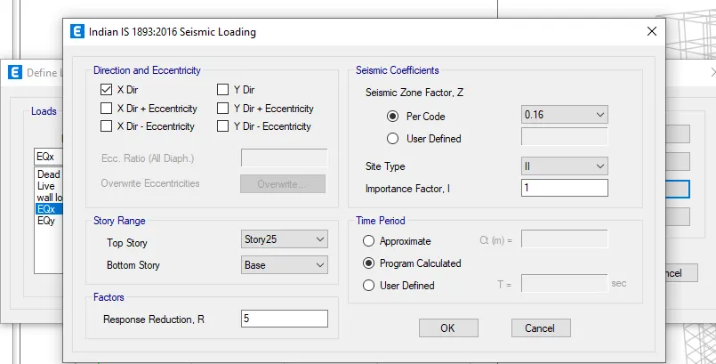
click on the seismic load in x-direction Then select the modify lateral load.
Except x direction uncheck all the direction.
Change the seismic zone factor to 0.16.
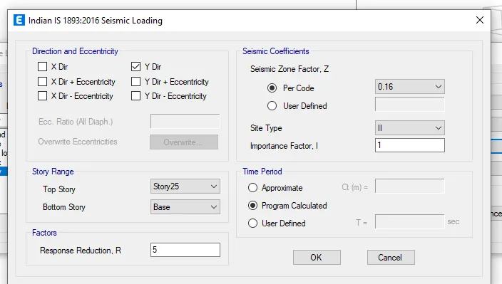
Click on the seismic load in y-direction then select the modify lateral load.
Except Y direction uncheck all the direction.
Change the seismic zone factor to 0.16.
After making all the setting in the load pattern.click on ok.
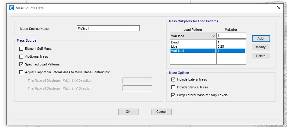
To define the mass source.
click on the define Then click on the mass source.
Check only the specified load patterns. select the load patterns of dead load of 1 multiplier live load of 0.25 multiplier wall load of 1 multiplier. then click ok.
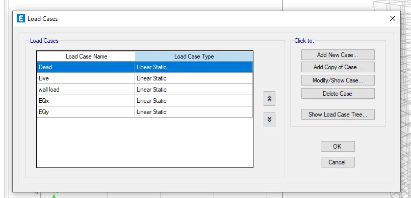
Then click on the define load cases. then click ok.
Then click on the define then click on the load combination.
Then click on the concrete frame design and convert to user combination.then click ok.
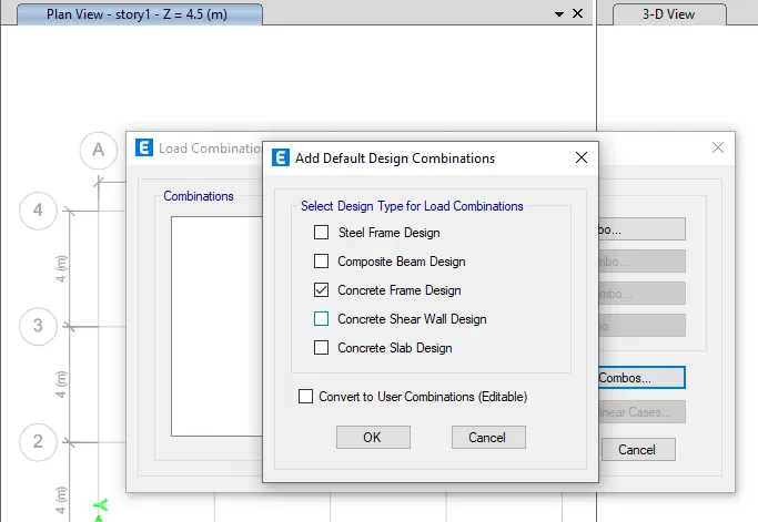
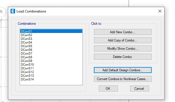
After selecting the concrete frame design.all the load combination are automatically appears here then click ok.
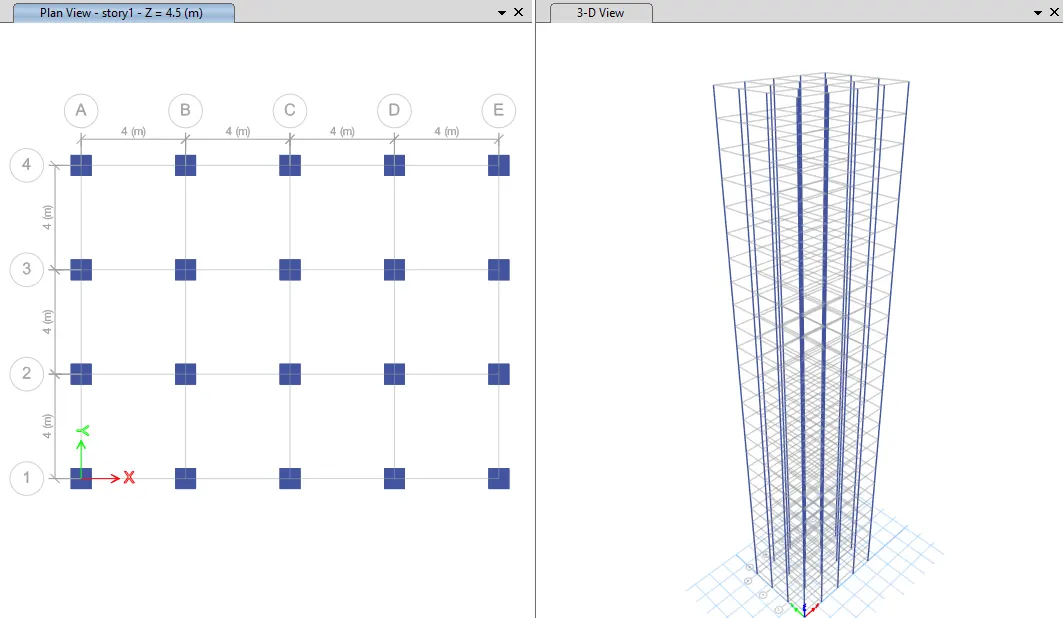
Draw the column at the junction of the grid lines.
click on the quick draw column icon in the tool bar.
place the mark at the junction of the grid lines.
Then the column will appear at the junction.
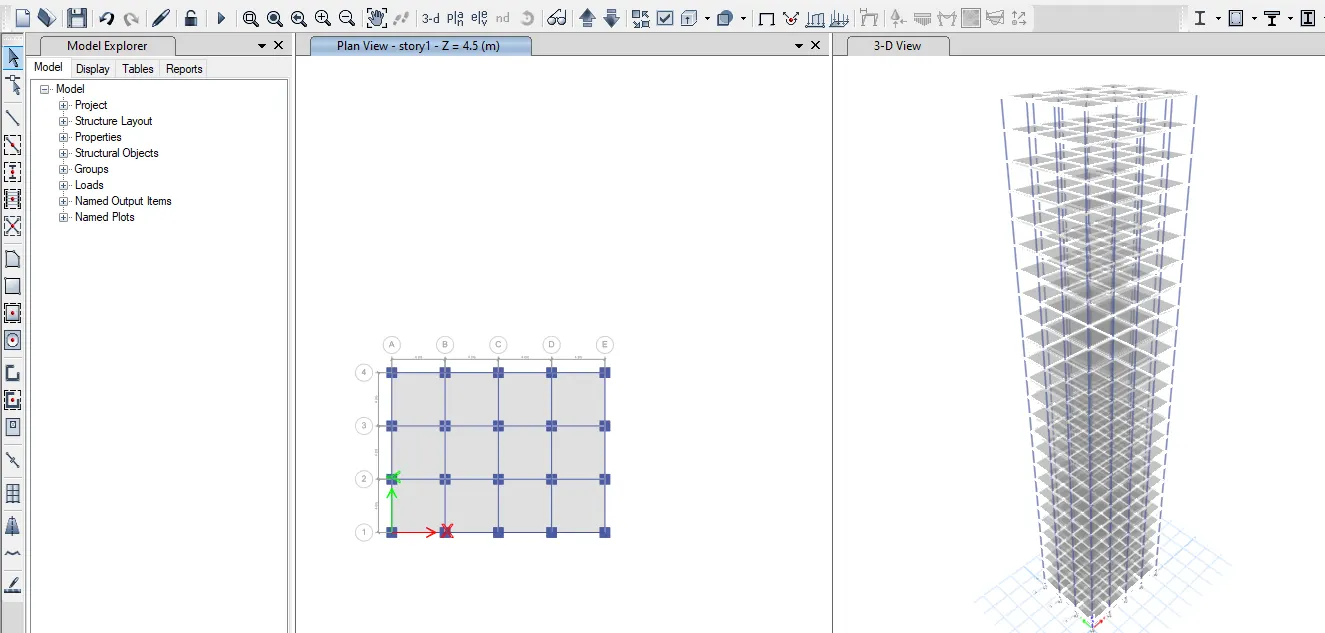
Draw the beam along the junction of the gride lines.
Click on the quick draw beam icon in the tool bar.
The size of beam should be 300x400mm
Place the mark along the junction of the grid.
Then the beam will appear along the junction.
Draw a slab in the model.
select the quick draw floor/wall to draw the slab.
Ensure that the selected property is slab 150.
click on select then click on select then click on properties then select the frame section.
Then select all the beams.
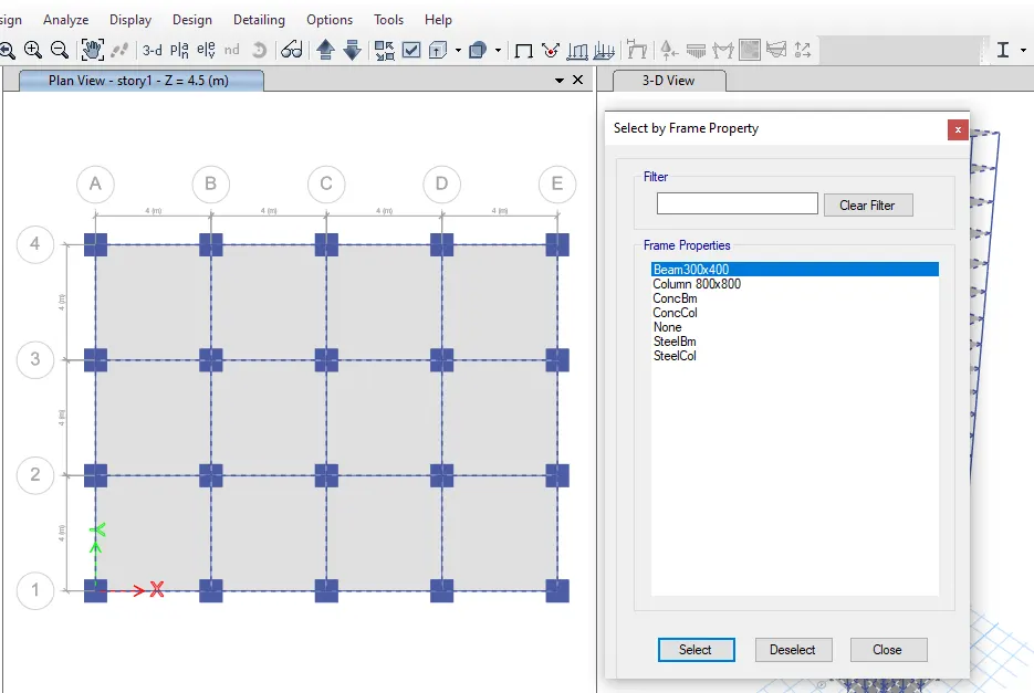
Assign the loads for the frame element.click on the assign then click on the frame load then click on distibuted.
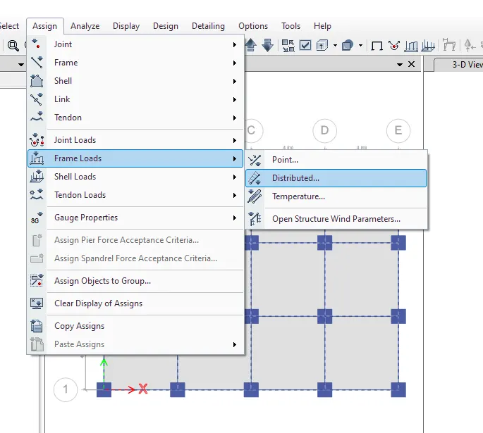
To select the slab sction. then select a assign then go to shell load then select a distibuted.
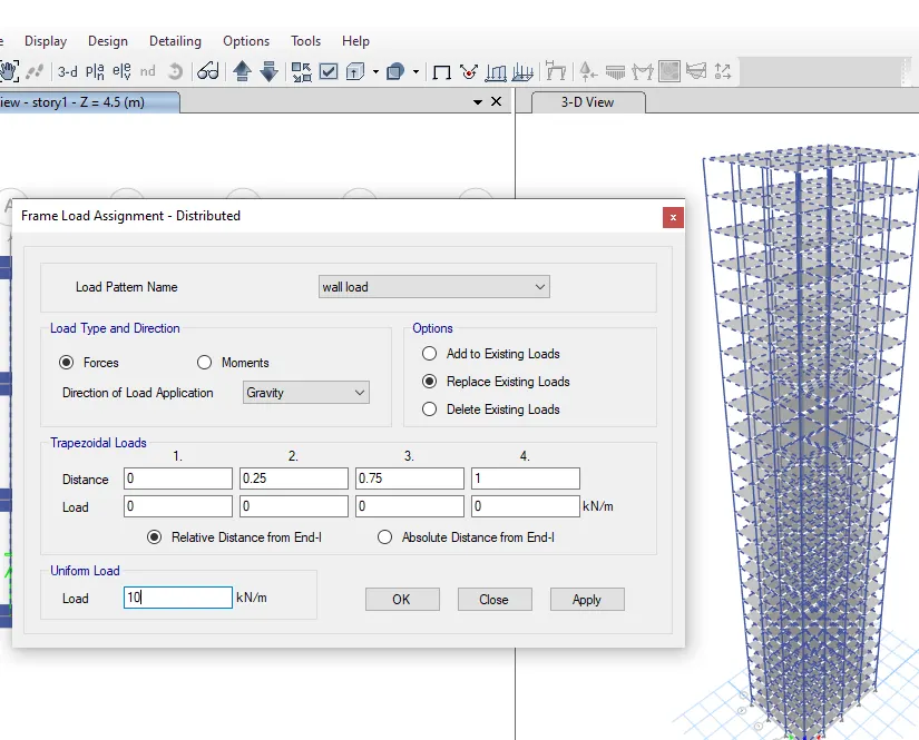
Select the load pattern as wall load.
Then take a uniform load as a 10kn/m.
Then click on apply then click ok.
After applying the 10kn/m load.then assign the load.
To select the slab section.
Click on select Then click on select Then click on properties then select the slab section.
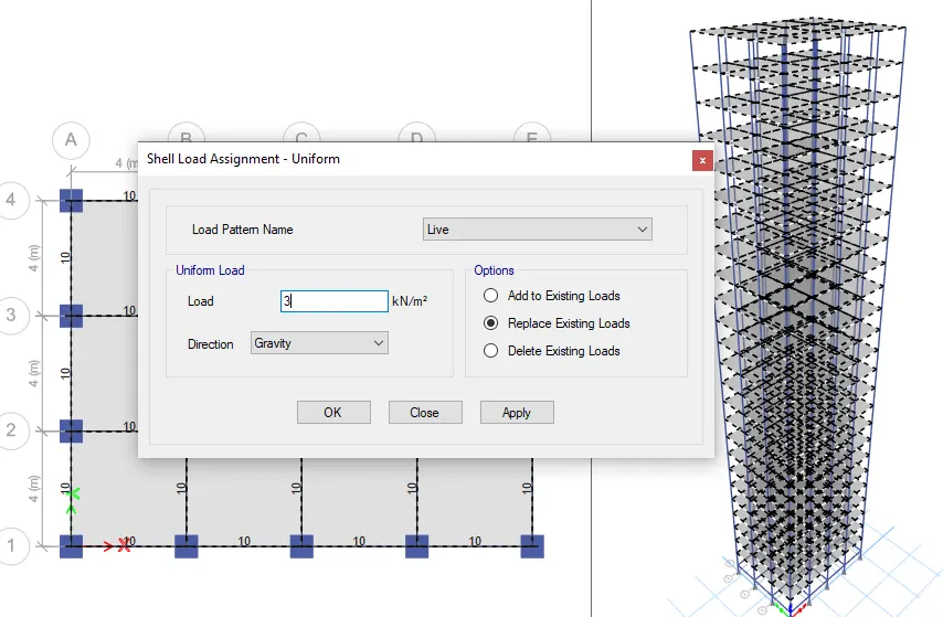
To assign the loads to the slab.
Click on the assign then click on the shell load then click on uniform.
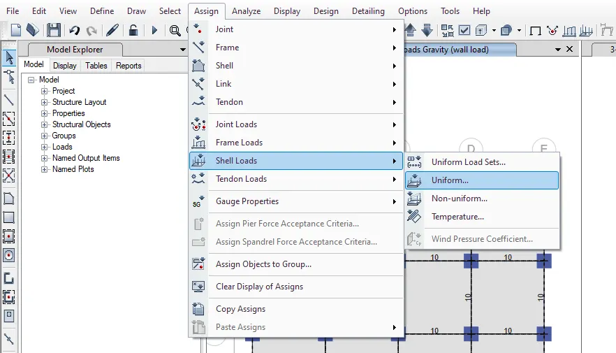
Select the load pattern as live.
Then take a uniform load as a 3KN/m
Then click on apply then click on ok.
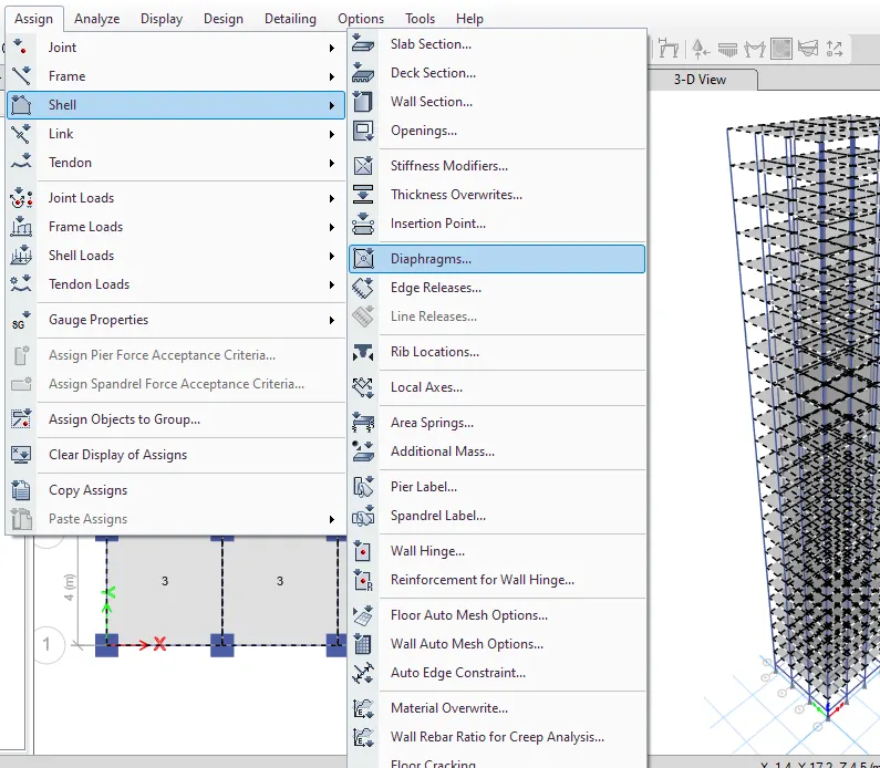
To provide the diaphragm.
First select the slab section.
click on assign then click on shell then clickk on diaphragm.
The diaphragm dialouge box opens.
Then select the diaphragm assignment as D1
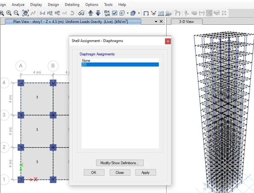
Then click on apply Then click on ok.
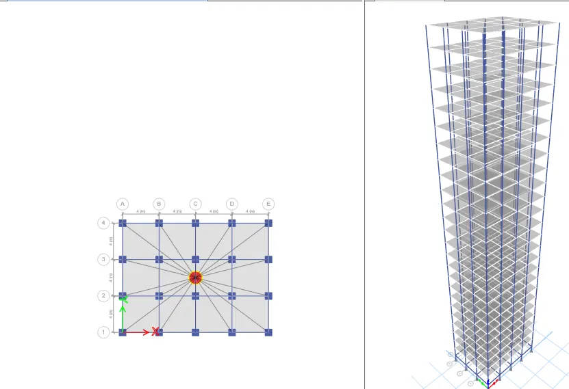
At last run the analysis by clicking the run analysis button.
RESULT:
Comaprision of time period for the building model
Criteria Desirable solution Exercise result
Fundamental translational
natural period X - Direction 4.4 s 4.85 s
Y - Direction 4.2 s 4.65 s
Torsional irregularity
IS 1893- Torsional mode time
2016 period should be lesser Yes (3.6s)
(Part 1) than X and Y direction
Table 5 time period
Vertical irregularity IS 1893-2016 First three mode together Yes (In the first
(Part 1) should contribute at least 65% mode only it
Table 6 Clause in mass participation factor occupies the
in each principal direction 85%)
Fundamental lateral natural No (If we
periods in two principal deduct the
plane directions are away 10% then
from each other we will get
by at least 10% a answer
as 3.37
but the
mode 1 and
mode 2
almost same)
Inter storey drift IS 1893- Storey drift Yes (The
2016 (Part 1) shall not storey
Clause 7.11.1.1 exceed 0.004 drift in
times the EQx we
storey height get near
for the base 1.35 and
shear with in EQy
no load we get
factor (4x10^-3) slightly
greater
than
1.35)