Modelling of 25 storey building with the specified properties using ETABS
Answer to the question
Question:
ETABS modelling of a 25 storey building
Model a 25 storey building on ETABS with structural properties as specified below. Ground floor or plinth floor level can be taken at a height of 1.5 metres from the base. Each of the successive 25 storeys has a storey height of 3 metres.
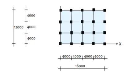
Structural Element Sizes
- Beams : 300 × 400 mm
- Columns : 800 × 800 mm
- Slab : 150 mm thick
Material Properties
- Grade of Concrete : M30
- Grade of Steel Reinforcement Bars : Fe 415
Loading
- Dead Load on beams from infill wall : 10 kN/m (Let us assume the same for roof floor in view of parapet)
- Live load on floor : 3 kN/m2 (Let us assume the same for roof floor)
a) Buildings are assumed to be pinned at the base
b) All columns in all storey are of the same size
c) All beams in all storeys are of the same size
d) Building is located on Soil type-II and in Zone-III. Assume other factors if required
Answer:
AIM:
Aim to the question is to modelling a 25-storey building with the help of ETABS software.
INTRODUCTION: in this question, we have to model a building of 25 Storeys. we have to use Etabs software and to create th building we will use the given column , beams , slab wall etc dimension.
PROCEDURE: To answer the Question We have to follow the following steps.
STEP-1
- First we have to open the ETAbs Software.
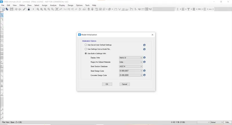
- Go to model initiation.
- Now go to use buid in setting with...set display unit Metric SI
- Steel secttion Database indian
- Steal design code IS: 800: 22007
- Concrete design code IS;456: 2000
- press ok.
STEP-2
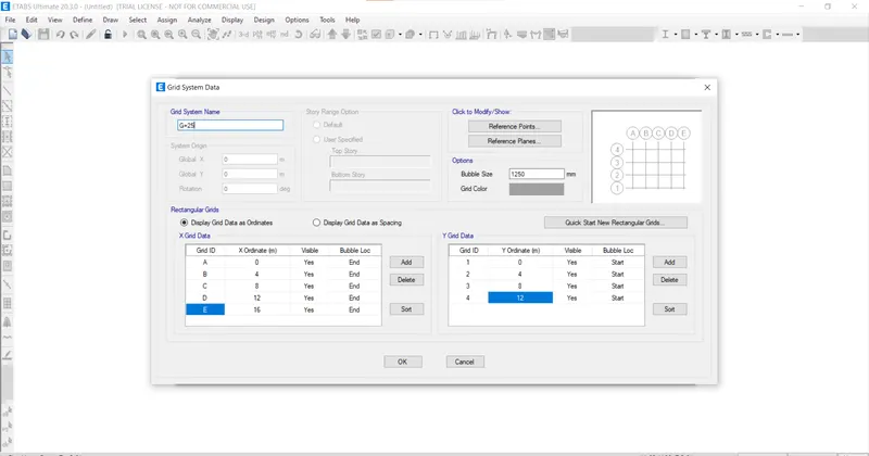
- Now go to Custom Grid spacing
- and Edit Grid data
- set grid spacing unit 4 and X Grid provide A, B, C,D, E
- And Y grid Provide 1,2,3,4 with spacing of 4.
STEP-3
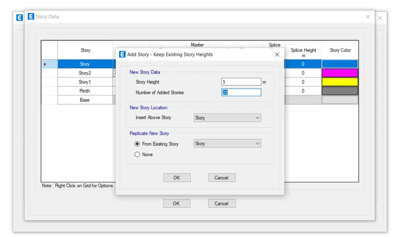
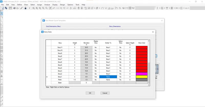
- Now go to custom story data and
- go to edit story data.
- Provide the Plinth data height 1.5m and story height is 3m
- After that go to story and add 22 another story
STEP-4
- Now add 22 another story and name it as story 1 to story 25 add story 1 is master story and put all story as a story1
- replicate story1 to all story.
- press ok.
STEP-5
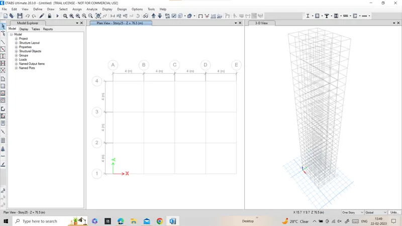
- Now we can see the 3 view and grid form is showing in the window.
STEP-6
- Go to define and
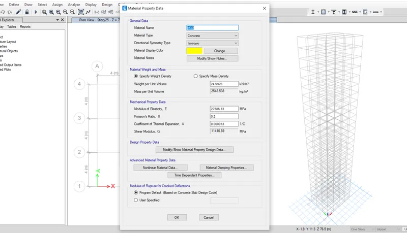
- Go to material Property add new material properly
- Select Region-India, Material Type-Concrete, Standard-Indian, Grade-M30
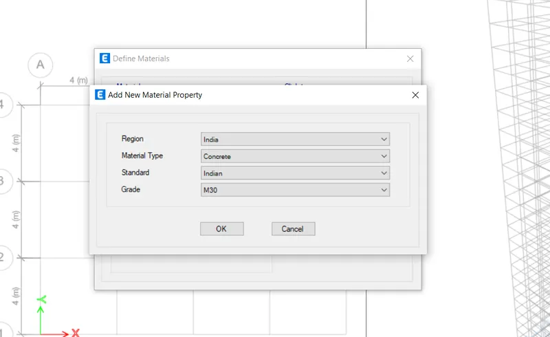
- Press ok.
STEP-7
- Again go to material Property add new material properly Rebar
- Select Region-India, Material Type-rebar , Standard-Indian, HYSD-415
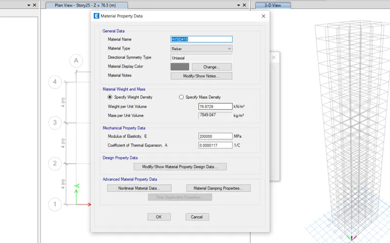
STEP-8
- Now go to define and section Property
- Click to the frame section.
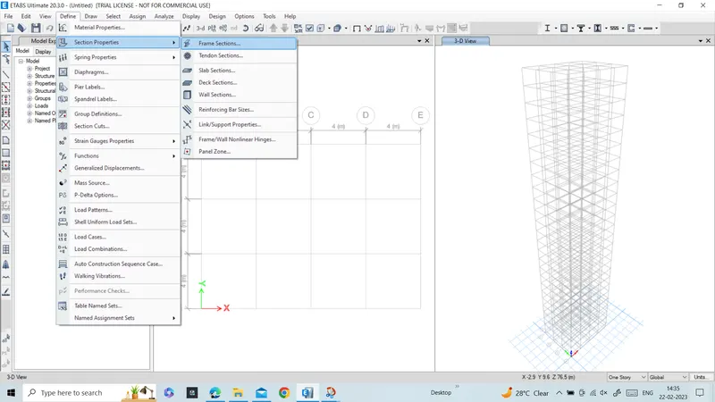
STEP-9
- Go to add new Property and choose shape for beam.
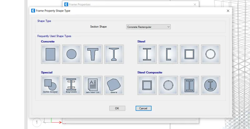
STEP-10
PROPERTY MODIFIER
- Put the property name as 300x400
- put the beam's depth and width.
- go to modify show modification
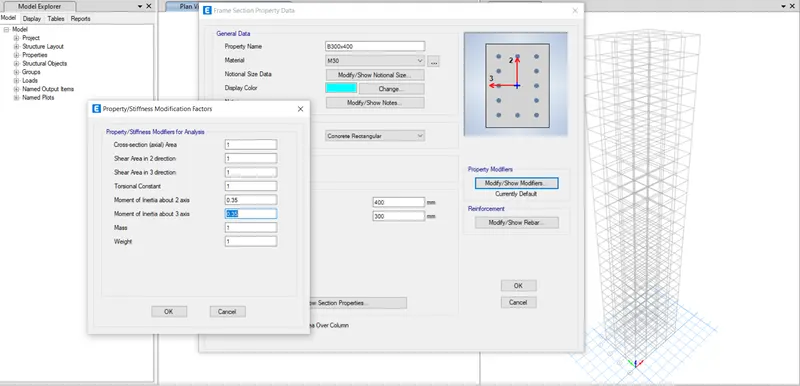
STEP-11
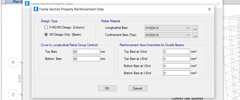
REINFORCEMENT
- Select design type as M3 Design Only (Beam)
- Select Rebar material Longitudinal Barrds - HYSD415
- Confinement Bar- HYSD415
STEP-12
- Again Choose the frame Property shape type for Column
STEP-13
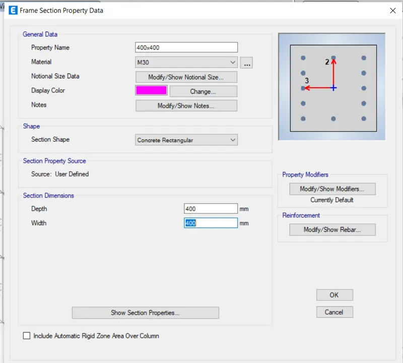
- Go to frame property list.
- put property name 400x400
- Material M30 put column Name
STEP-14
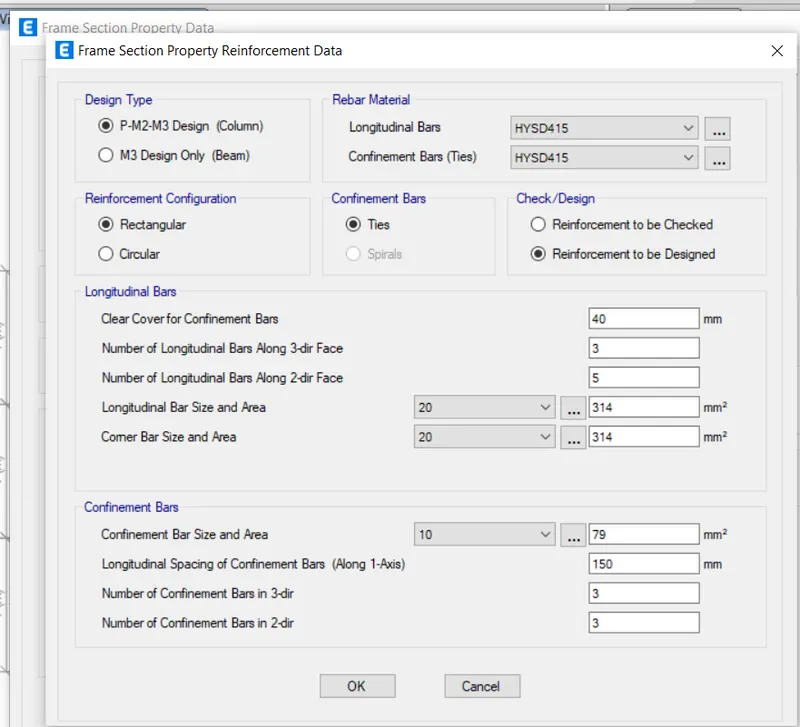
Reinforcement
- Go t0 reinforcement option and choose the column and choose the rebar material Longitudenal Bars As a HYSD 415
- and Confinement Bars HYSD415
STEP-15
SLAB;
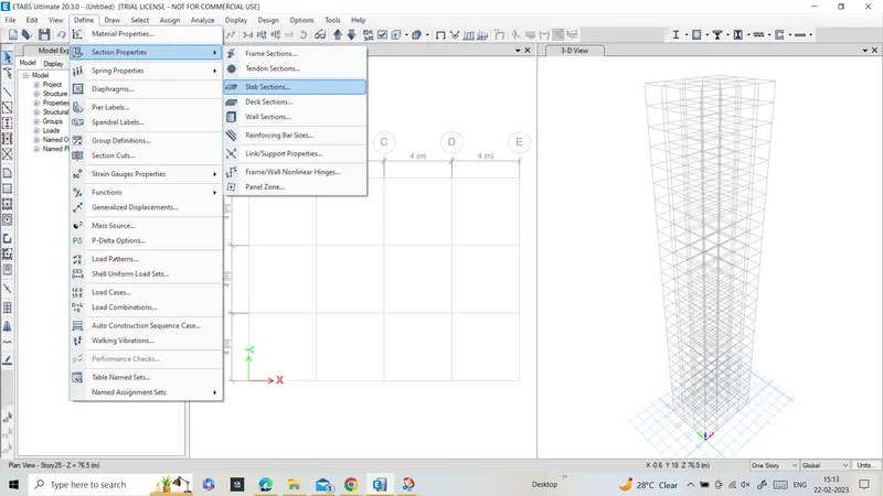
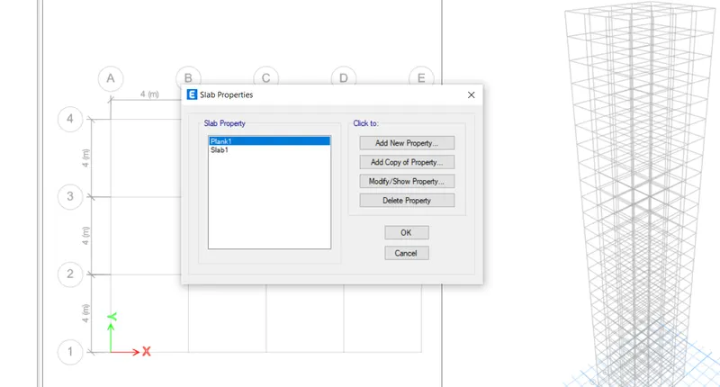
- Now we are going to Slab definition.
- Go to Define and after that go to section Property
- Now Go to Slab Sections.
STEP-16
- Click to the Slab Prorperty data
- And add new Property.
STEP-17
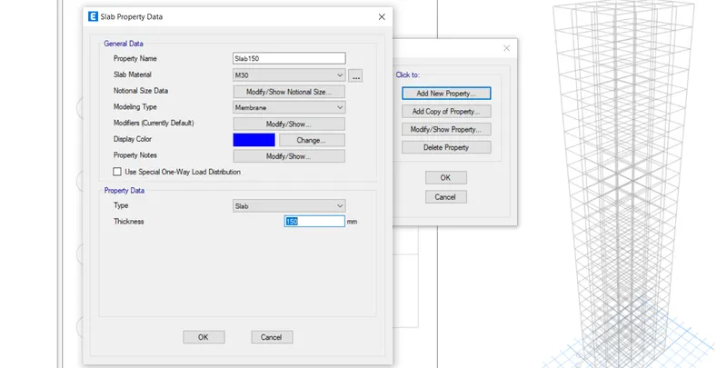
- Now Put the Property name Slab150
- Material M30
- modelling type Membrane
- slab thickness 150mm
STEP-18
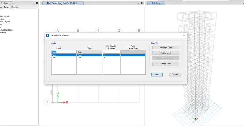
- Click to the define and go to the load patterns.
- And start to add load.
STEP-19
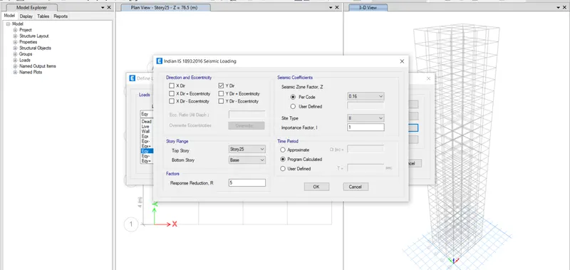
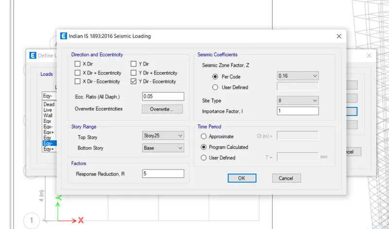
LOAD PATERN
STEP-20
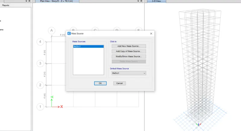
MASS CONSIDERATION:
- Go to define and
- k to the mass source.
- and ad new Mass source.
STEP-21
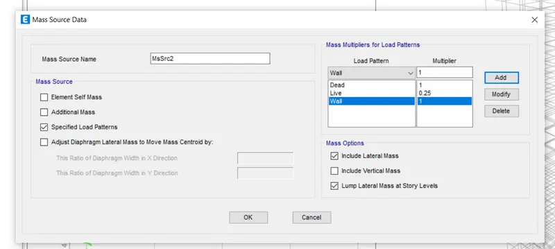
- we get the new dialog box
- select the Specified Load Pattern
- Add wall load as 100%
- Live load 0.25%
- and Dead load !00%
- Click Ok
STEP-22
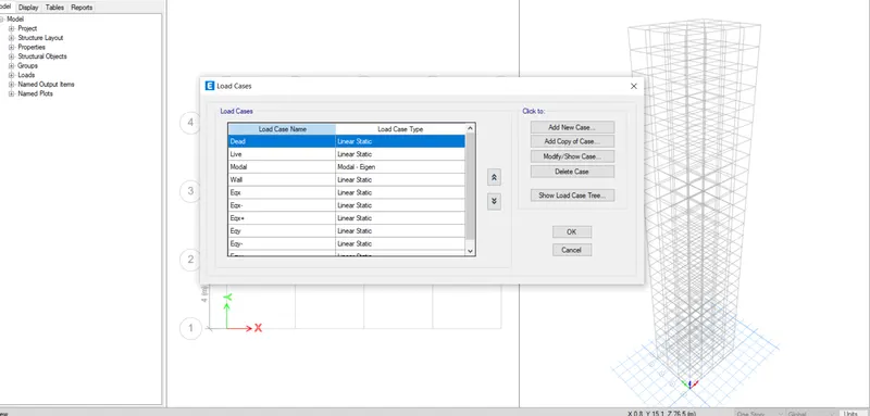
LOAD CASES
- NOW check the load cases.
STEP-23
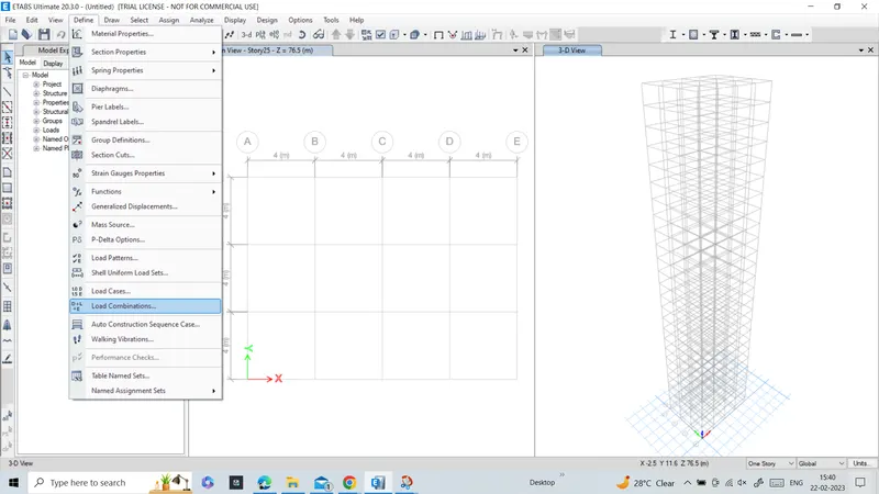
LOAD COMMBINATION:
- For this go to define
- and click to the option Load combination
STEP-24
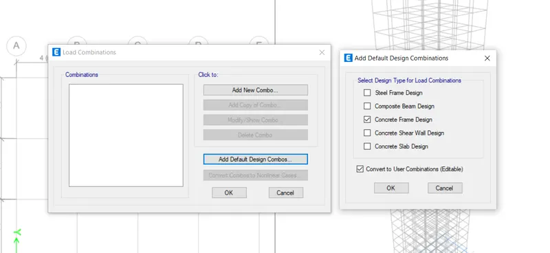
- Click to the add default Design Combinations....
- And click Concrete Frame Desing
- After that click convert to user Slab Design
- And press ok.
STEP-25
MODELLING STAGE:
COLUMN
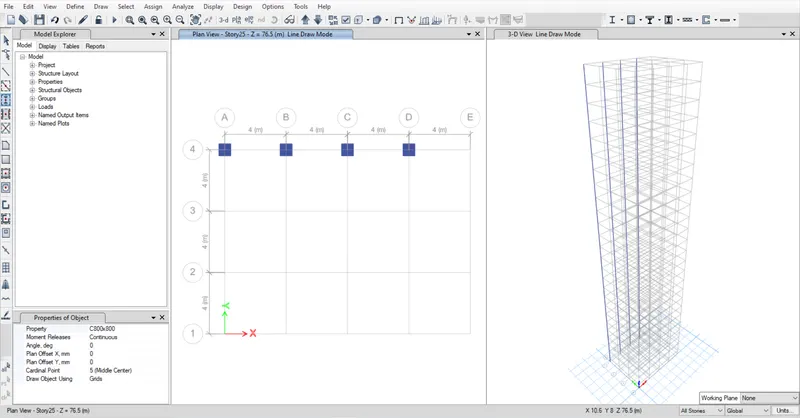
- Go to quick draw column:
- now go to Property of the Object and select the column propery which we created.
- next select the all story and start to putiing the column in grid lines.
STEP-26
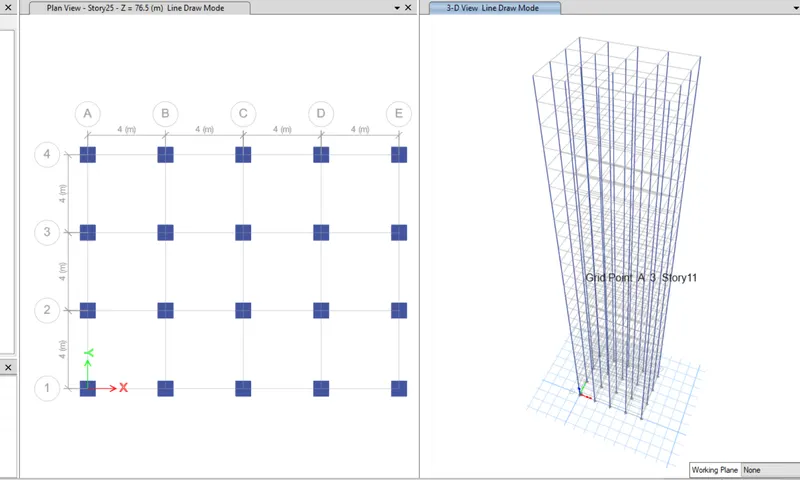
- We can see we are created the column with all the story in the screenshot
STEP-27
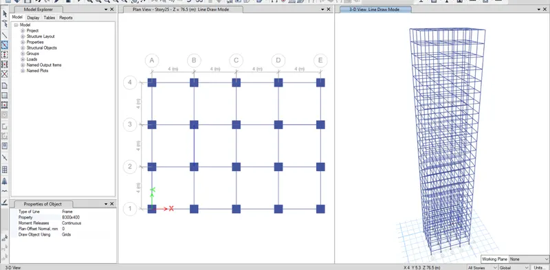
BEAM CREATION:
- Go to quick column beam and select the option
- Go to property and choose the beam and
- start to connecting the beam.
- We also can use the select option or we can put it manually.
- Now in 3d structure we can see we created the all beams in the building.
STEP-28
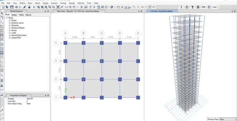
SLAB
- Now go to story one and change to it similar story.
- Go to quick floor a
- Go to property and choose the slab150
- start to putting the slab
- We also can use the select option or we can put it manually.
- Now in 3d structure we can see we created the all slab in the building.
STEP-29
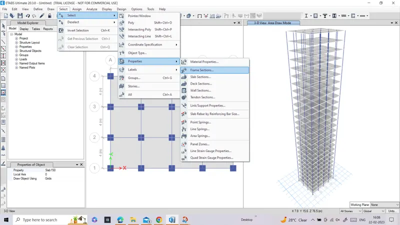
- Now go to select
- go to properties
- click frame section.
STEP-30
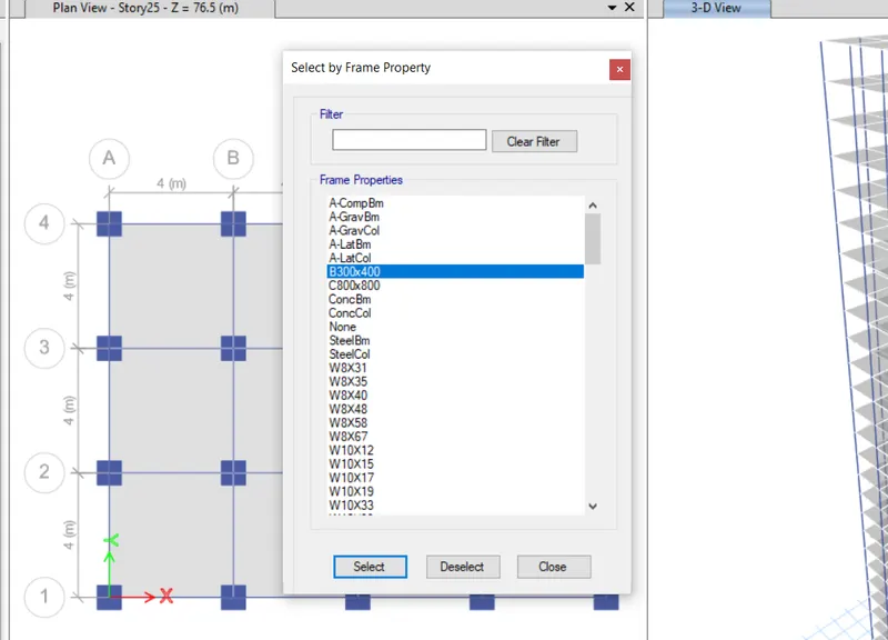
- in the Frame property select the Beam Size B300X400
STEP-31
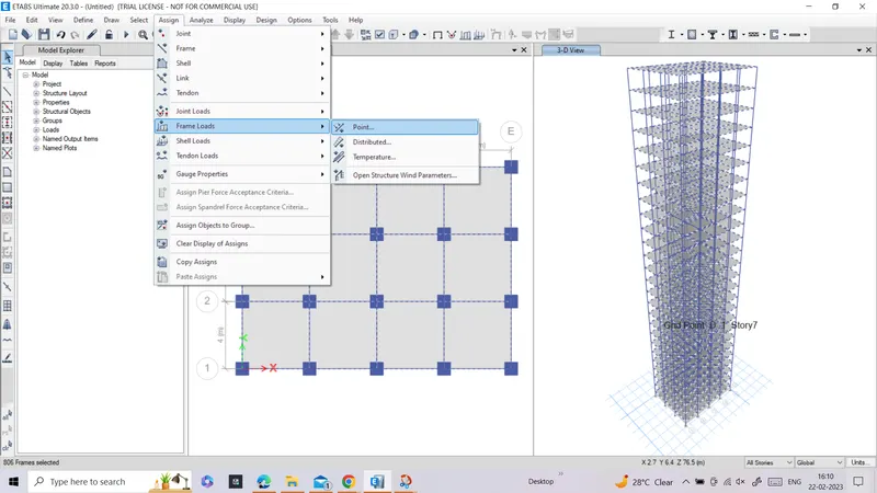
- Now we have to assign
- for that go to Assign
- click to the load
STEP-32
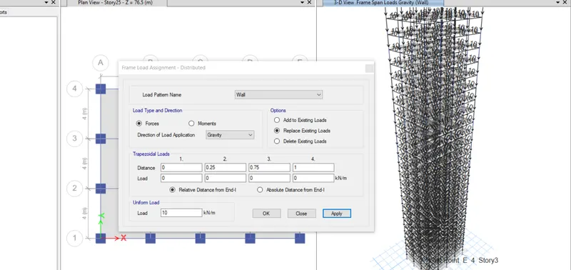
WALL LOAD:
- Go to load distribution and click choose wall load option
- and put wall load as 10kN/m
STEP-33
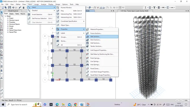
- For Slab go to Select
- Go to properties after that go to Slab sections.
- in the dialog box select the slab 150.
STEP-34
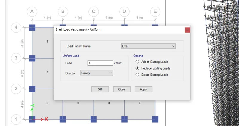
- go to assign and click to the shell load
- choose the live load
- put facto 3 kN/ m
STEP-35
- Again go to select and g to slab section and choose slab 150 and select.
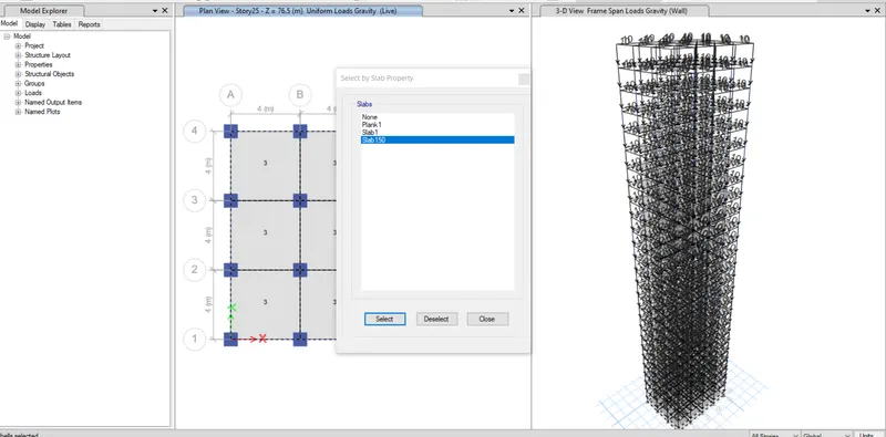
STEP-36
- Now go to shell
- go to diaphragm
- select d1 and click to the apply.
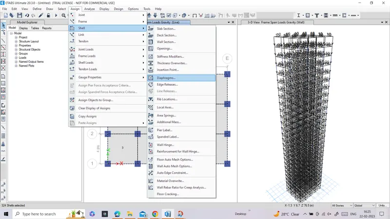
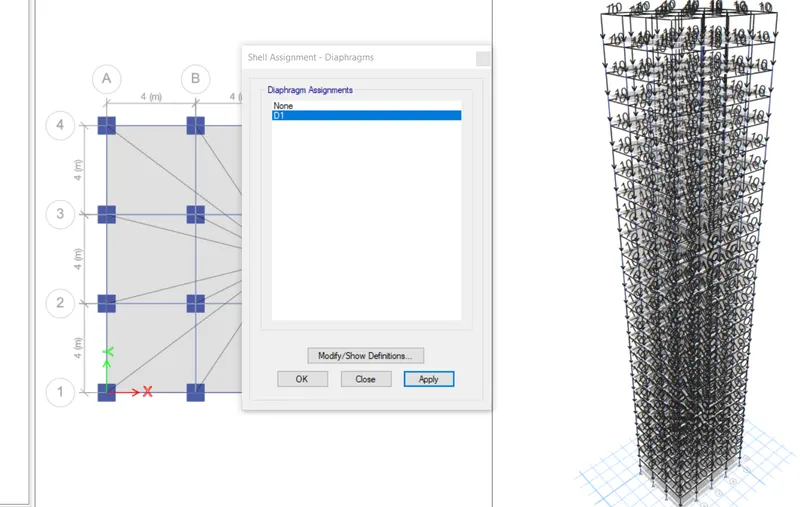
STEP-37
- Now we can see the center of mass already calculated.
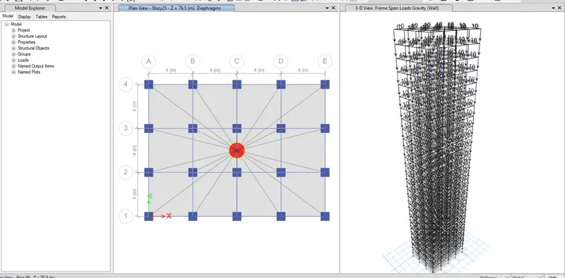
STEP-38
Go to analysis button and click to the analysis .
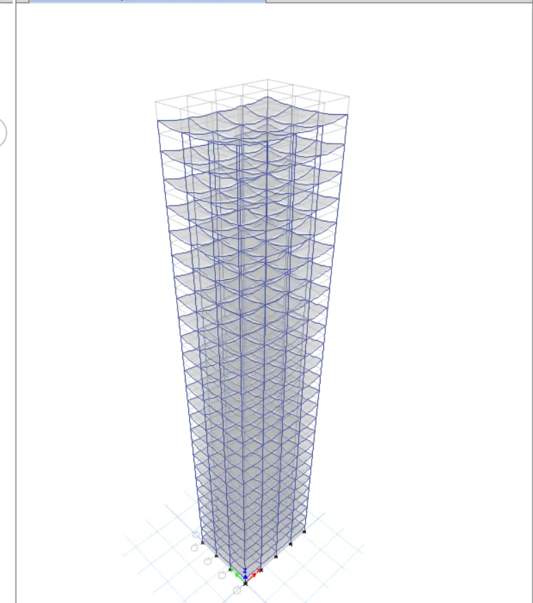
STEP-39
Exercises:
Answers
| Fundamental Translational natural period | X-Direction | 4.4 second | 4.41 |
| Y-direction | 4.2 second | 4.22 | |
| Torsional irregularity | IS 1893-2016(Part-1) table-5 | Torsional mode Time period should be lesser than X And Y direction time periods | Yes |
| Vertical Irregularity | IS 1893-2016(Part-1) Table-6 Clause-7 | First three modes togeher should contribute at least 65% in mass particulation fcctor in each principal direction | Yes |
| Fundamental lateral natural periods in two principal plane direction are away from each other by at least 10% | No | ||
|
Inter -Stoey drift |
IS-1893-2016(Part-1) Clouse-7.11.1.1 | Storey drift shall not exceed 0.004 times the storey height for base shear with no load factors(4x10^3) | Yes |
RESULT: We created the 25 story building with the help of ETABS software. in the story we add the columns , Beams and load we add the live load, Wall load and after that