Modelling of 25 storey building with the specified properties using ETABS
Aim - Modelling of 25 storey building with the specified properties using ETABS
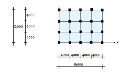
Introduction - Model a 25 storey building on ETABS with structural properties as specified below. Ground floor or plinth floor level can be taken at a height of 1.5 metres from the base. Each of the successive 25 storeys has a storey height of 3 metres.
Structural Element Sizes
- Beams : 300 × 400 mm
- Columns : 800 × 800 mm
- Slab : 150 mm thick
Material Properties
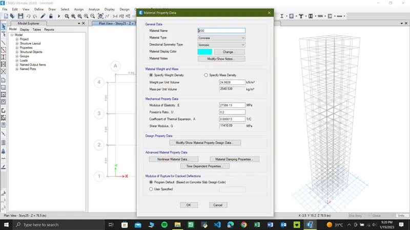
- Grade of Concrete : M30
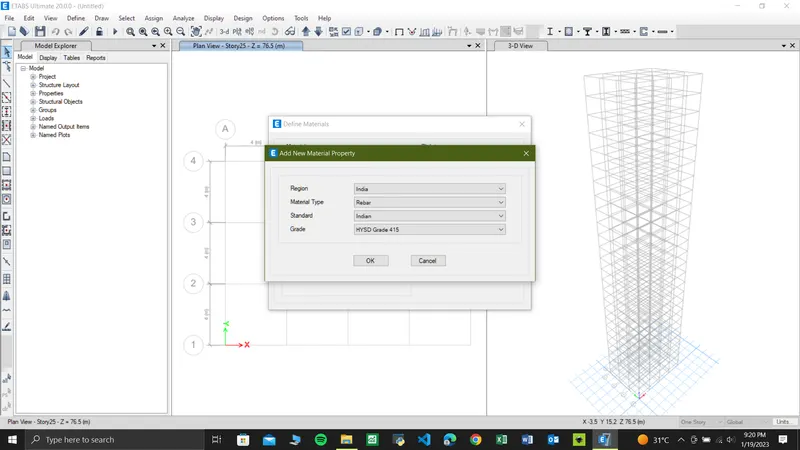
- Grade of Steel Reinforcement Bars : Fe 415
Loading
- Dead Load on beams from infill wall : 10 kN/m (Let us assume the same for roof floor in view of parapet)
- Live load on floor : 3 kN/m2 (Let us assume the same for roof floor)
a) Buildings are assumed to be pinned at the base
b) All columns in all storey are of the same size
c) All beams in all storeys are of the same size
d) Building is located on Soil type-II and in Zone-III. Assume other factors if required.
Procedure -
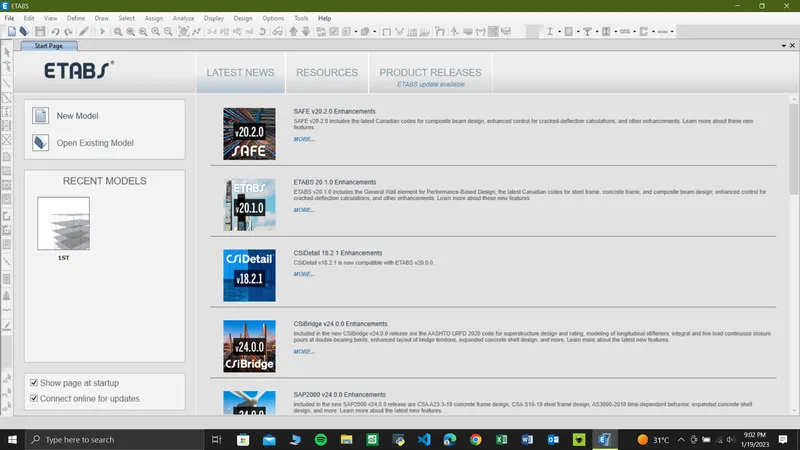
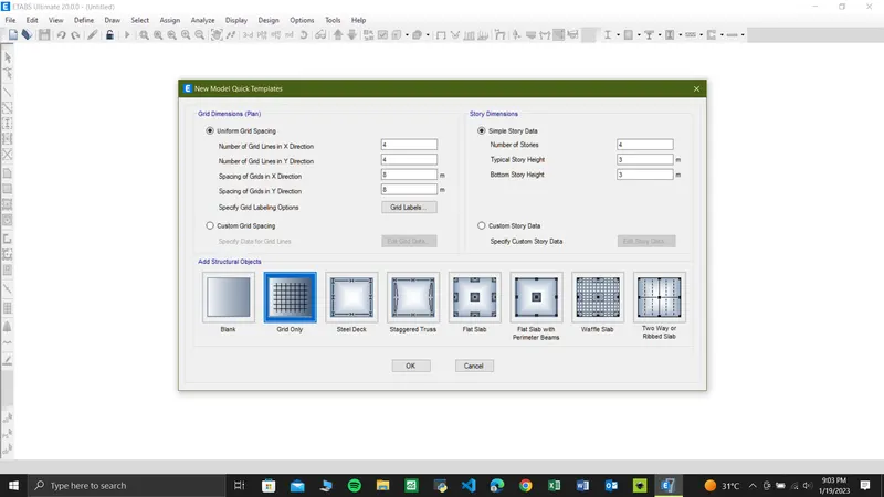
1. Open new file
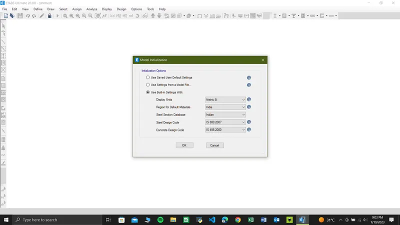
2.then add the Indian code and SI units
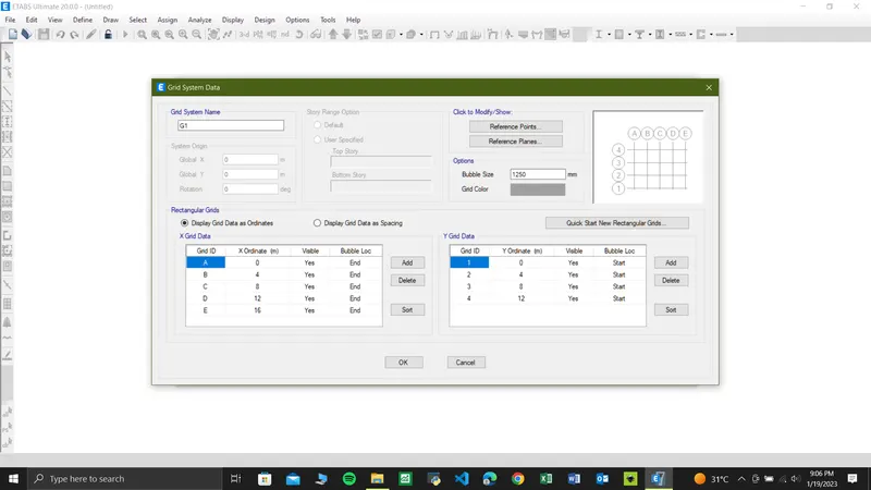
3.create the grids as given in the question 5 column 4 rows at a 4m distance
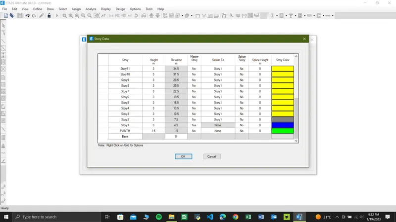
4 . Create the 25 story at 3m distance plinth at 1.5 m and assign 1st storey as master storey and other stories similar to the 1st storey.
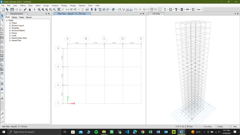
5.then click ok we will see the plan and 3d view of the grids provided
6.then go to define - add new materials concrete and steel concrete of M30 grade and rebar of Fe 415
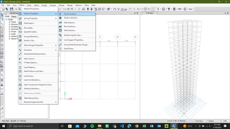
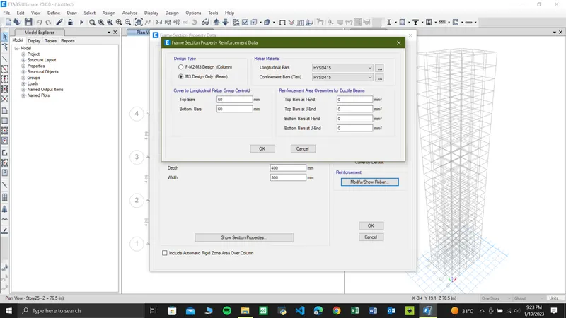
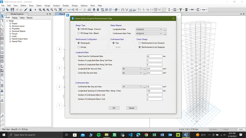
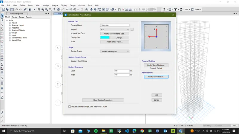
7.then go to define - section property - frame section then add new beam and column section select the proper material and the rebar
Beam - 300 x 400
Column - 800 x 800
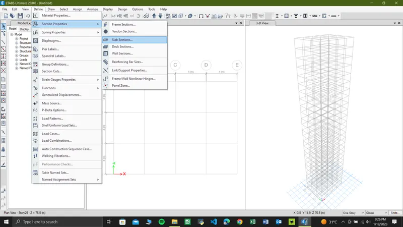
8.then go for the define - slab section - add new property give the thickness of slab 150mm and modelling type membrane and materials.
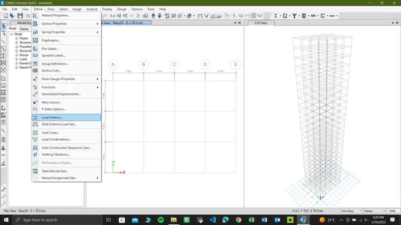
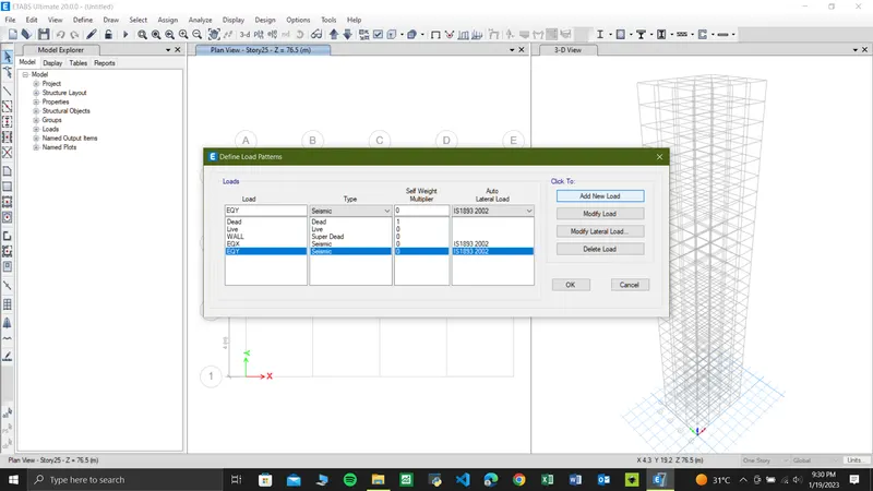
9. Go for define load patterns add the load patterns live , dead, wall, EQX and EQY
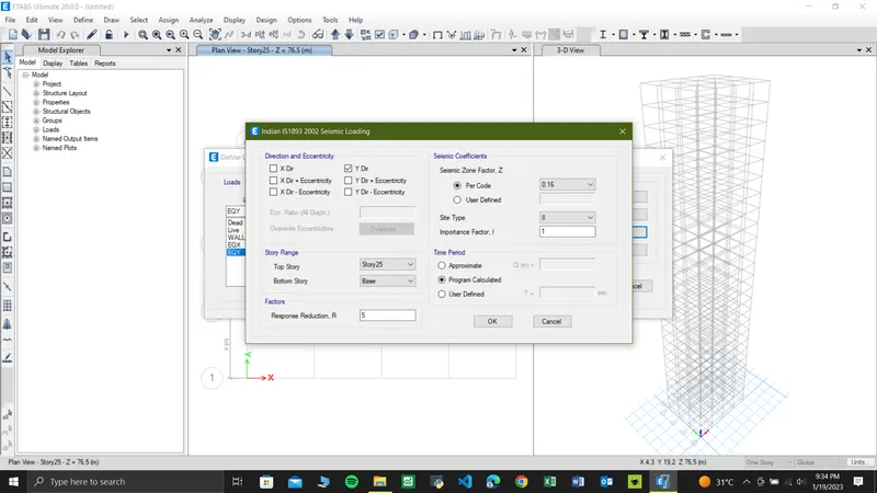
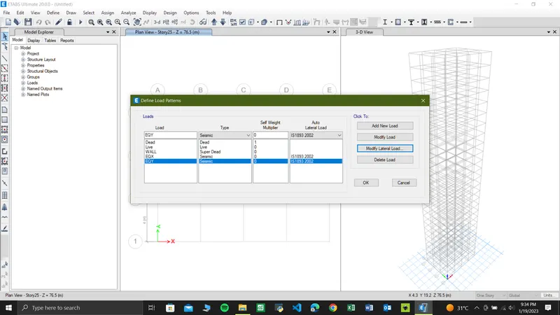
And for EQX and EQY modify the lateral load
Direction and eccentricity for EQX - X for EQY - Y
Seismic zone - 3
Site type - 2
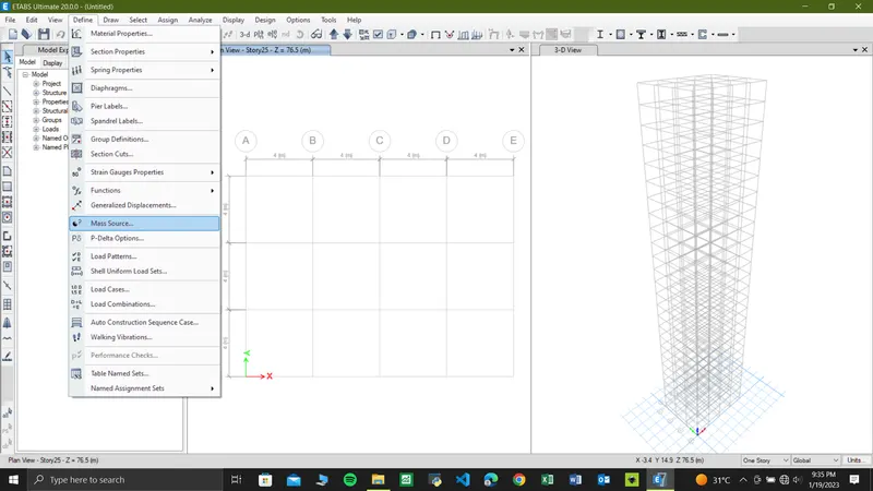
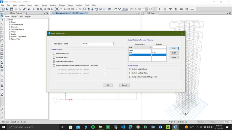
10. Then define the mass source
100 % of dead load
25% of live load
10. Then check the load cases of all the loads are present
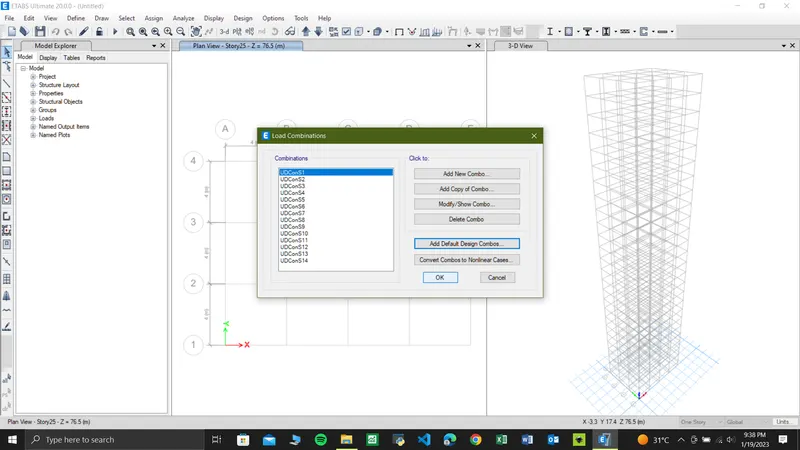
11. Then go to define and create load combination
12. After this start modelling beam and column and slab
13.start with modelling column go to quick draw and select the column property we created C800X800 and place on the intersection of grids
14.for beam go to quick draw beam select the property we created B300x400 and model the beam on the grids
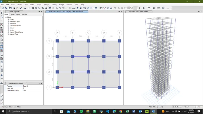
15.then place the slab by using quick slab and keep the similar story option
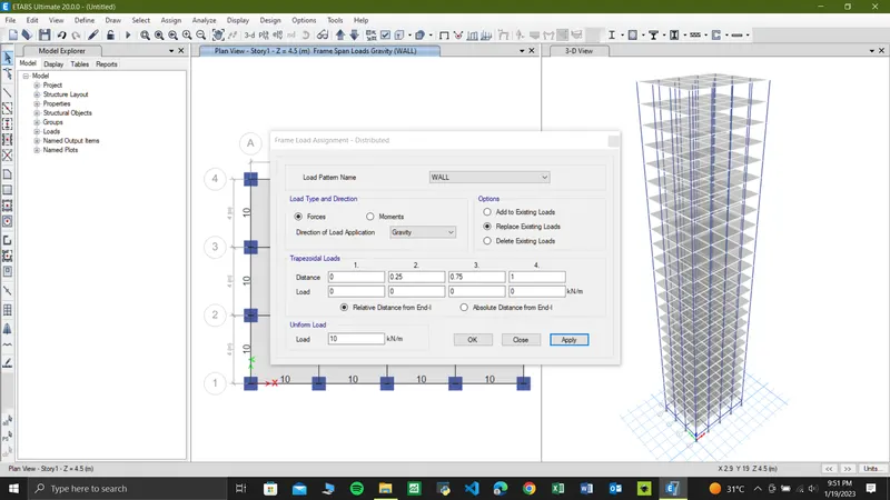
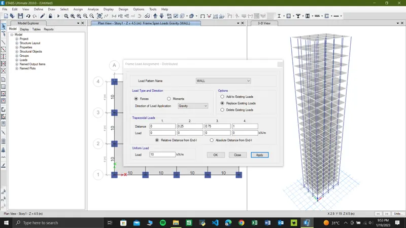
16.then go to select and object type then select all the beam and then go to assign - frame load - distributed - load pattern - wall . Load - 10kn/m
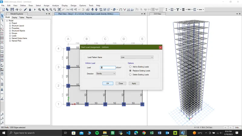
17.than select the floors assign 3kn/m of live load
18.then select all the slabs and assign diagrams
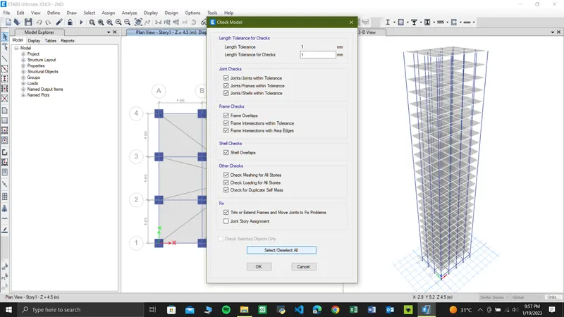
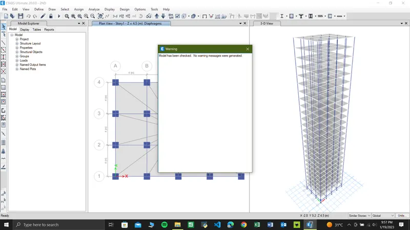
19. everything is done then check the model from analyze tab
20.once model is checked then run analysis
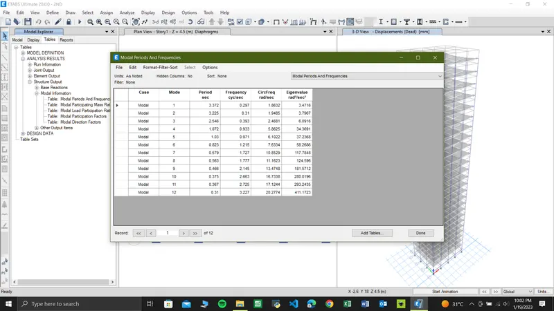
21.the for period sec go to tables - analysis results - structure output - model information - modal periods and frequencies
For mode 1 - 3.372
Mode 2 - 3.225
Mode 3 - 2.546
Which is lesser than mode 1 and mode 2
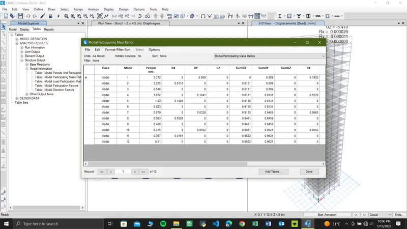
22.first 3 modes are contributing at least 65% in mass participation factor
Step by step procedure with screenshots -
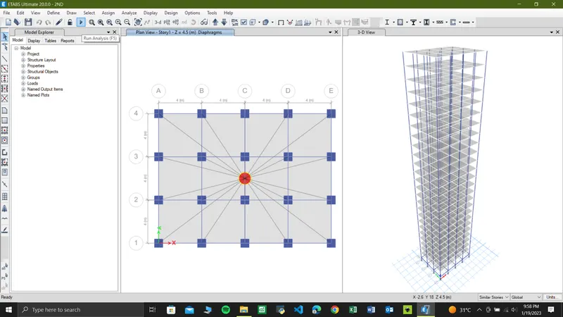
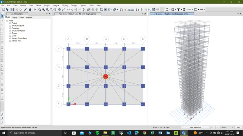
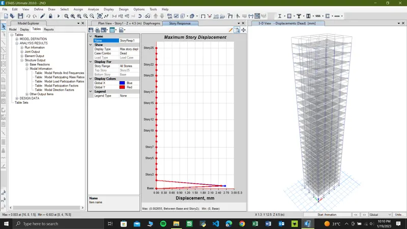
Result -
- Check if the translational fundamental natural period of vibration in both the x and y direction is approximately:
Tx= 4.4 second - 3.372
Ty= 4.2 second - 3.225
This check will help confirm if modelling is done correctly. Some deviations from the above values is possible (± 2%). But any major deviation will suggest an error in modelling.
- Check if the following provision in Table 5 of IS 1893 (part 1) – 2016, on torsional irregularity satisfied: Yes
The natural period corresponding to the torsional mode of oscillation must be less than the two fundamental translational modes of oscillation along each principal plan directions.
- Check if the two provisions of clause 7 in Table 6 (shown below) of IS 1893 (part 1) – 2016, regarding vertical irregularity is satisfied - Yes
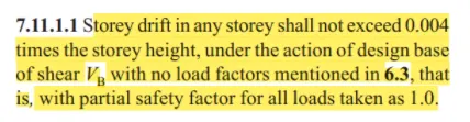
- Check if provision on inter-storey drift limitations in clause 7.11.1.1 satisfied. Please note that this check is for Serviceability Limit State and hence is for situation when stucture is subjected to unfactored seismic base shear - Yes