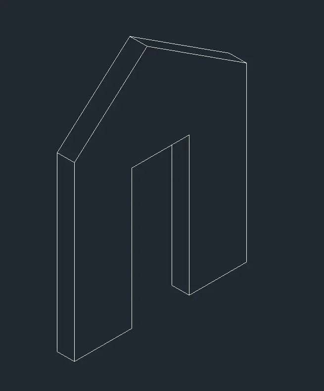
Creating a Floor plan, Footing detail and Isometric view using AutoCad
Q.1 Aim - Drawing c/s of load bearing wall by using AutoCAD
Itroduction - using necessary commands like, line, rectangle, polyline and modification tools copy, etc. i drew c.s of load bearing wall.
Procedure - 1. read the drawing carefully. see for all the dimensions needed to draw the fig.
2. open autoCAD select the unit.
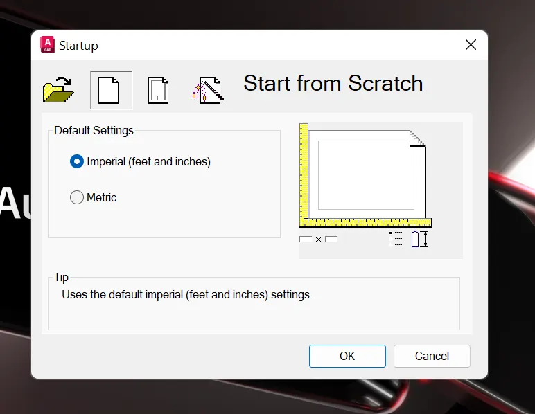
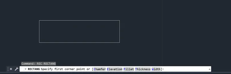
3. Start with the rectangle command . and draw rectangle of given dimension.
4. using line or polyline command draw the upper part according to the dimension-
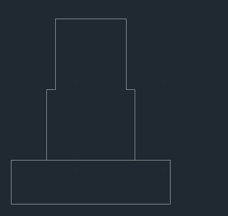
5.Draw side step parts using line command draw one step and copy the remaining steps at required distance.
Result -
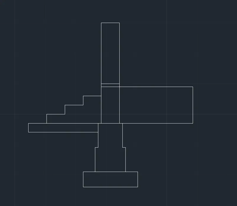
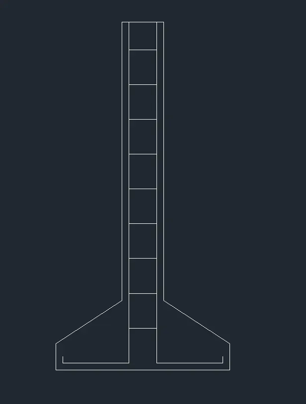
Q.2 Aim - Drawing c/s of isolated footing by using AutoCAD
Introduction -using necessary commands like, line, polyline and modification tools copy, offset etc. i drew c.s of isolated footing.
Procedure -
1. read the drawing carefully. see for all the dimensions needed to draw the fig.
2. open autoCAD select the unit.
3. Draw lower portion of footing using relative co ordinate system.
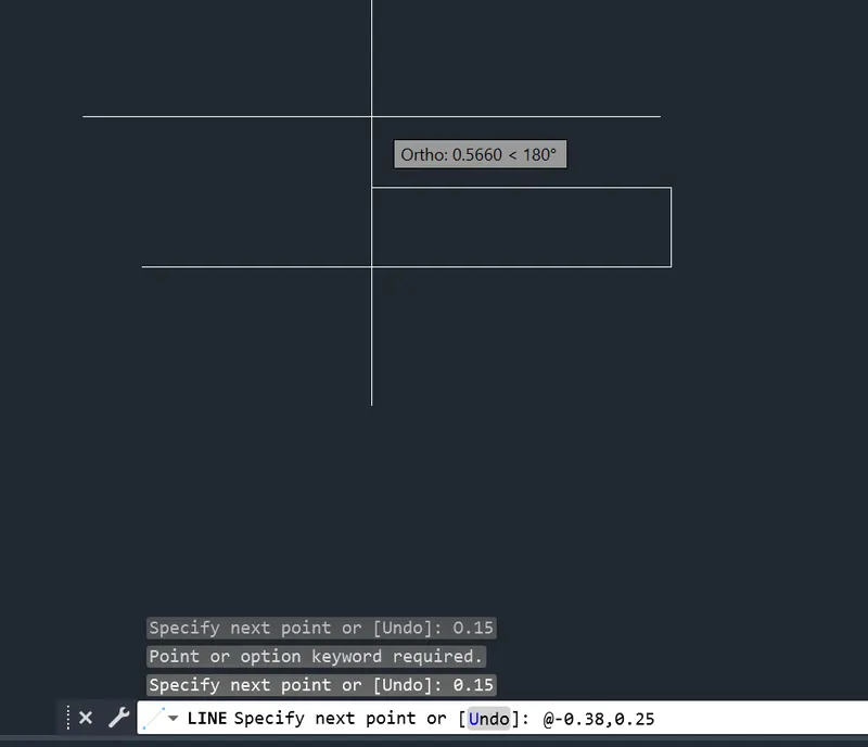
4. using mirror and line command prepared the outer portion of drawing.
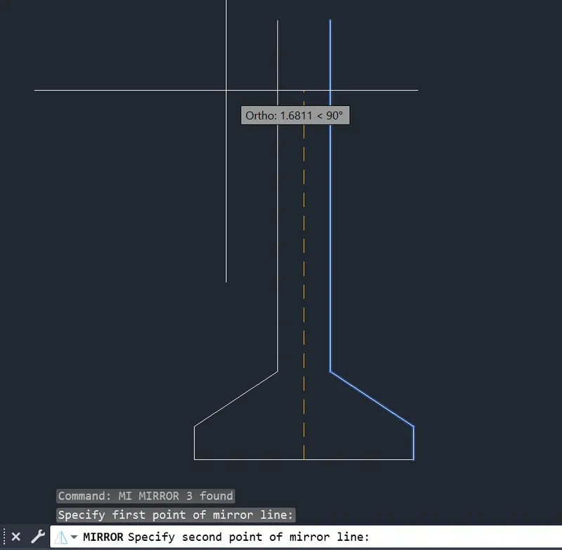
5.
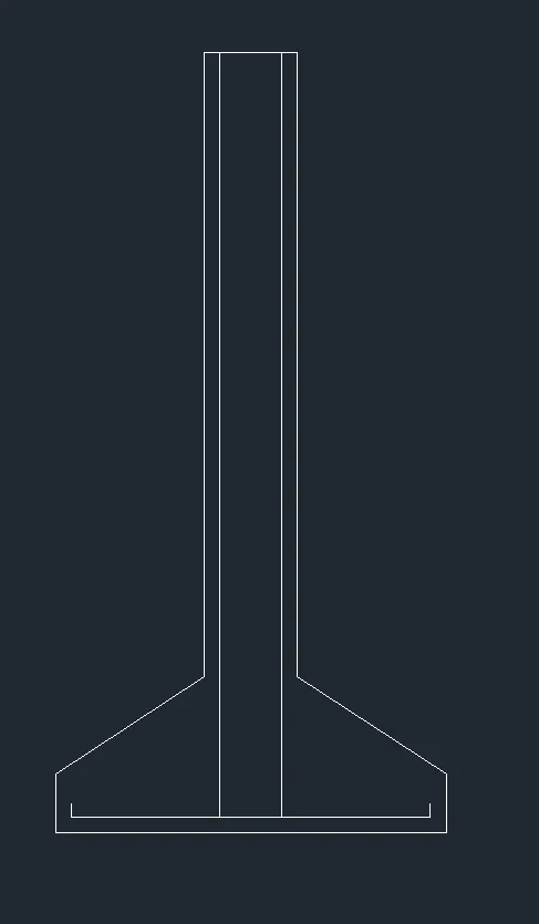
6. Drew the inner links of column using offset command
Result -
Q.3 Aim -To draw line diagram of two bedroom plan using AutoCAD
Introduction -using necessary commands like, line, polyline and modification tool offset etc. i drew line plan.
Procedure -
1. read the drawing carefully. see for all the dimensions needed to draw the fig.
2. open autoCAD select the unit.
3. Draw the outer part of the plan by using line command with given dimension.

4. Draw the steps shown in fig by using offset command.
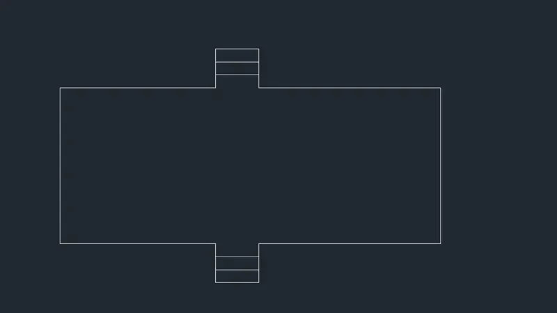
5. Finish up the plan by drawing internal walls by ine command.
Result -

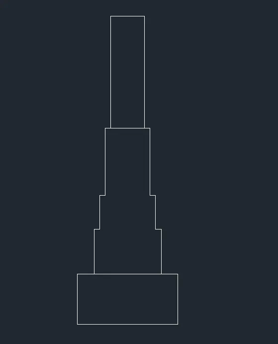
Q.4 Aim - To draw c.s of load baering wall showing foundation details.
Introduction - using necessary commands like, line, polyline and modification tool offset etc. i drew c.s of load bearing wall.
Procedure -
1. read the drawing carefully. see for all the dimensions needed to draw the fig.
2. open autoCAD select the unit.
3. draw the c.s using line and rectangle command.
Result -
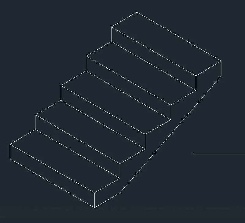
Q.5 Aim - To draw isometric view of steps
Introduction - using necessary commands like, line, polyline and modification tool offset, copy etc. i drew isometric view of steps.
Procedure -
1. read the drawing carefully. see for all the dimensions needed to draw the fig.
2. open autoCAD select the unit.
3. On the isometric grids
4. Draw one side of the steps -

5. Copy this to the other side
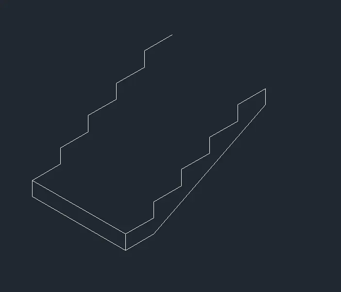
6. Join the steps by lines
Result -
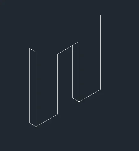
Q.6 Aim - To draw isometric view of gable wall
Introduction - using necessary commands like, line and modification tool offset, copy etc. i drew isometric view of gable wall.
Procedure -
1. read the drawing carefully. see for all the dimensions needed to draw the fig.
2. open autoCAD select the unit.
3. On the isometric grids
4.
Result -