Modelling of 25 storey building with the specified properties using ETABS
Challenge 6 – ETABS modelling of a 25 storey building
Model a 25 storey building on ETABS with structural properties as specified below. Ground floor or plinth floor level can be taken at a height of 1.5 metres from the base. Each of the successive 25 storeys has a storey height of 3 metres.
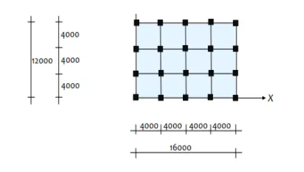
Structural Element Sizes
- Beams : 300 × 400 mm
- Columns : 800 × 800 mm
- Slab : 150 mm thick
Material Properties
- Grade of Concrete : M30
- Grade of Steel Reinforcement Bars : Fe 415
Loading
- Dead Load on beams from infill wall : 10 kN/m (Let us assume the same for roof floor in view of parapet)
- Live load on floor : 3 kN/m2 (Let us assume the same for roof floor)
a) Buildings are assumed to be pinned at the base
b) All columns in all storey are of the same size
c) All beams in all storeys are of the same size
d) Building is located on Soil type-II and in Zone-III. Assume other factors if required.
Aim: To model a 25 storey building using E-Tabs and to assign sizes, properties, loads of elements as per given data and to run analysis and check the results.
Introduction: Modelling in E-Tabs is purely for the purpose of structural analysis of the structure created.Unlike other software analysis and results of structure is based on the required codal provisions for eg: IS1893 code can be assigned for earthquake loads in the structure.The procedure of analysis also follows codal provisions and the results obtained are so accurate in the E-Tabs software. The sizes,properties,grid data and load are assigned to the structure as per the given data.
Steps:
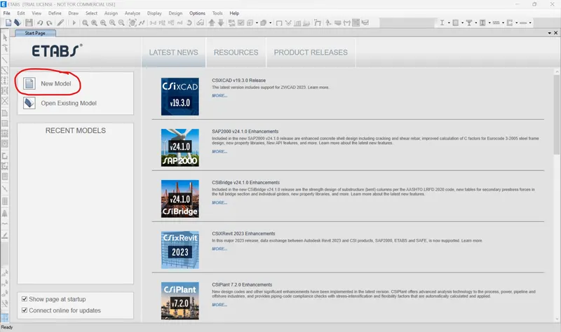
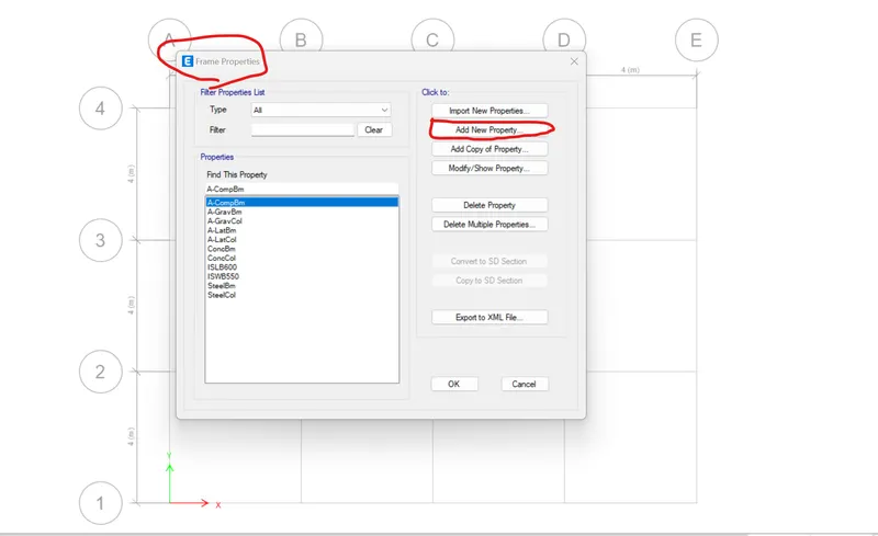
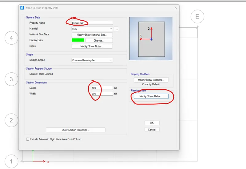
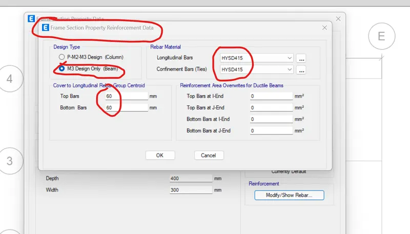
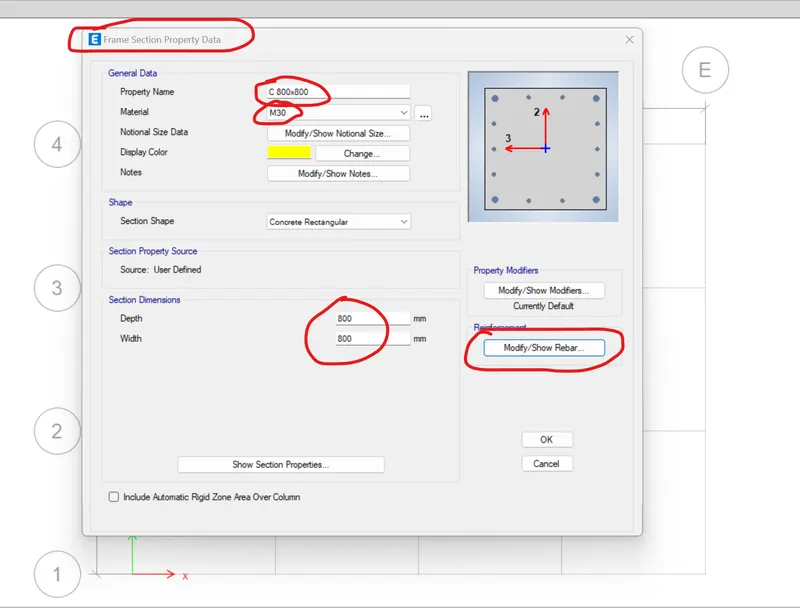
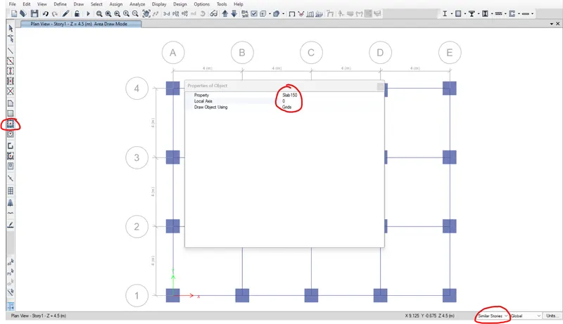
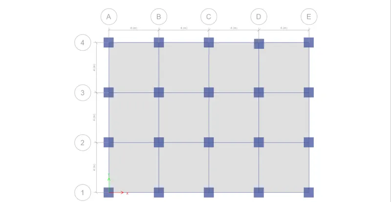
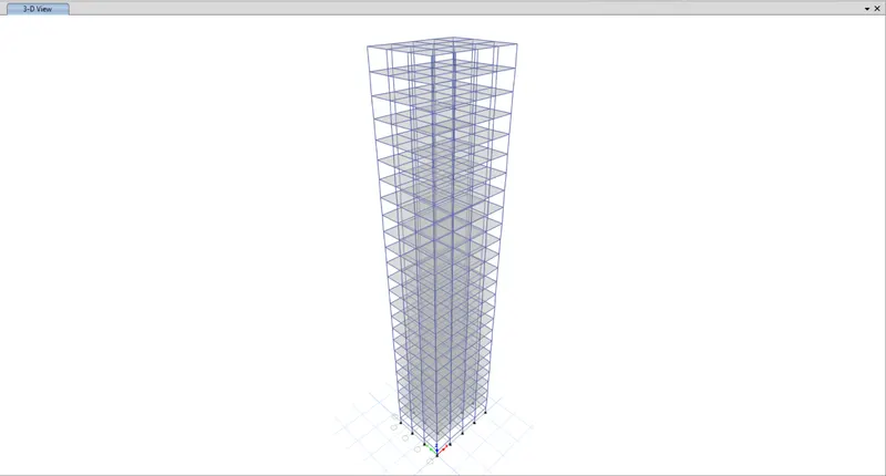
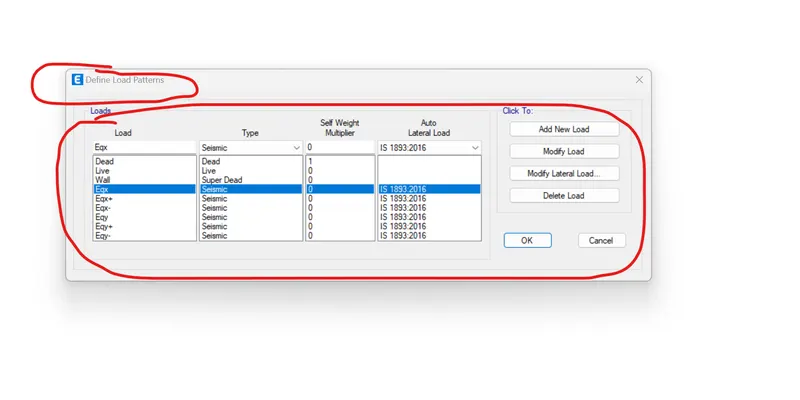
- Initially new project file option is selected in E-Tabs interface.
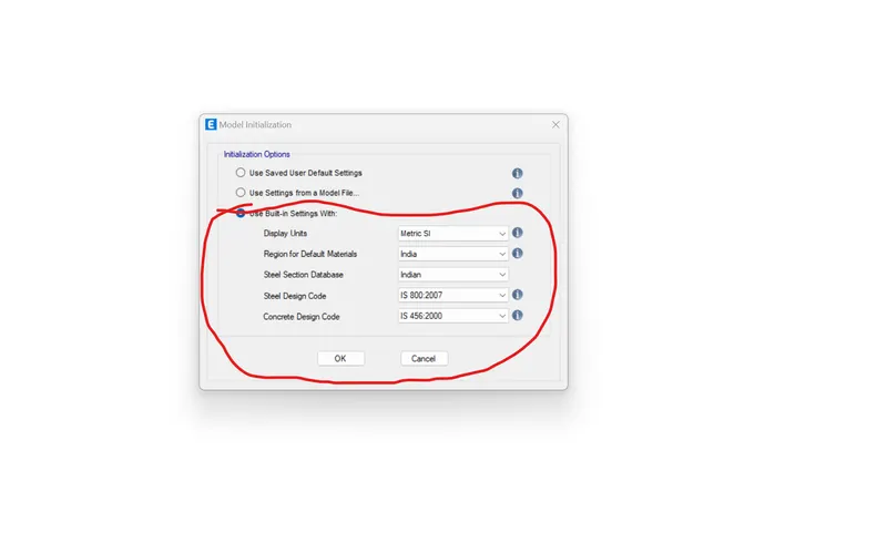
- After opening the project model initilaziation properties like units,region,code for the project are assigned
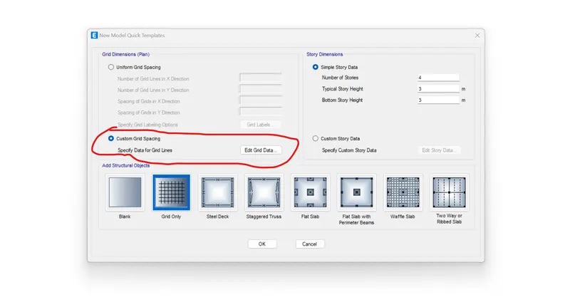
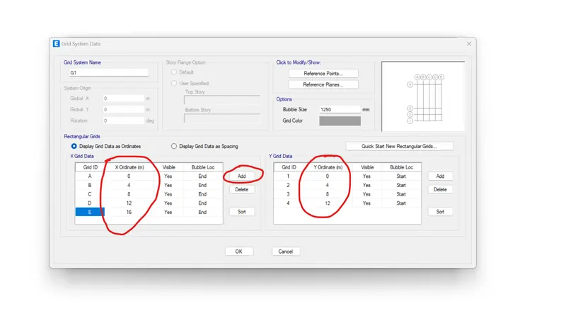
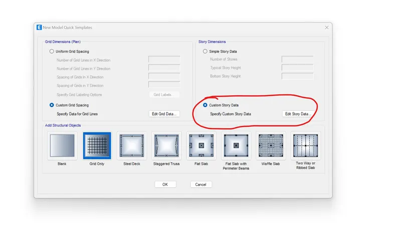
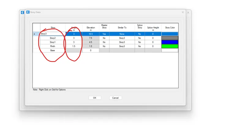
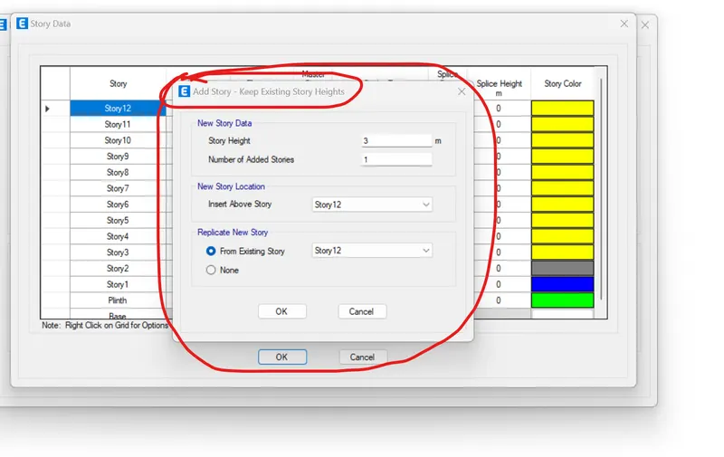
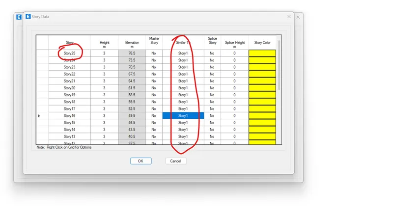
- Then grid and storey data are assigned by selecting custom grid and custom storey option and providing grid data as per given details and first storey is selected as master storey and all the storeys above are selected as similar storeys option so as to create a similar plan like 1st storey. Storeys are added using the add storey option and height can be given in the height column of the custom storey data and finally after entering all the data ok option is selected.
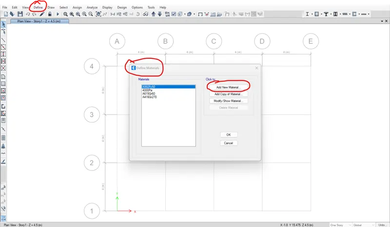
- Then in project model interface under define option from the top in the ribbon material properties and element sizes are defined
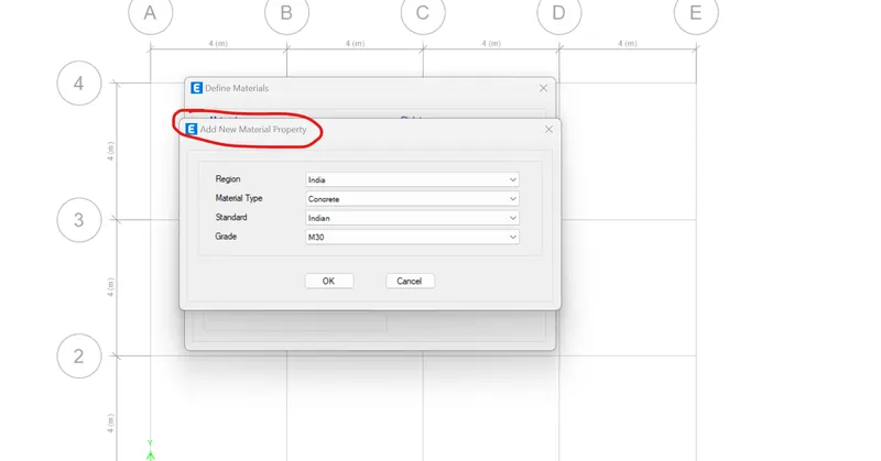
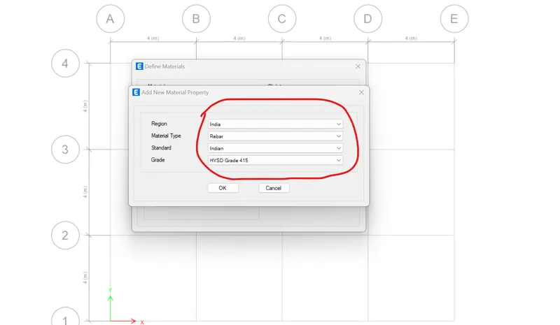
- By selecting define and material properties the material properties like concrete M30 and rebar as Fe415 by selecting add new material option and assigning property,region,standard and grade.
- Furthermore, structure element sizes are defined by selecting section properties option in the define command of the ribbon
- Then frame sections option is selected followed by concrete rectangular option and add new property option
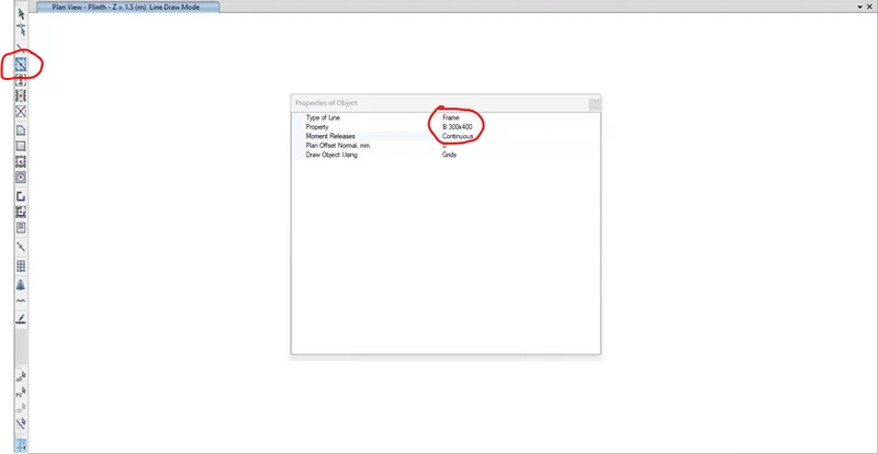
- Then the new property is named as B300x400 for beam and the sizes,material as M30 are provided and in the modify rebar option design beam only option is selected and the beam is assigned
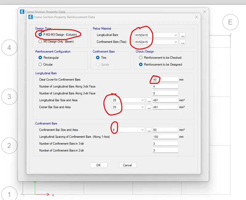
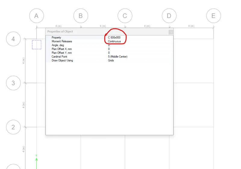
- Then in the same fram sections, concrete rectangular option, the same add new property option is selcted, then the new property is named as C800x800 for column and the sizes,material as M30 are provided and in the modify rebar option design column option is selected and the rebar material is provided as Fe415 and the column is assigned.
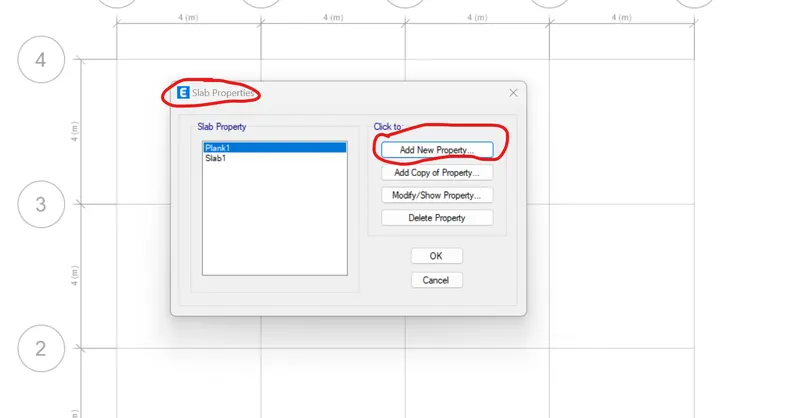
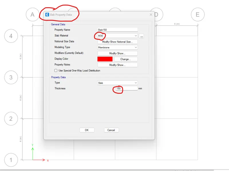
- Then for slab, slab sections option is selected from the section properties and in add new property option the slab is named as S150 and the thickness is given as 150mm and the material as M30 and the slab is assigned.
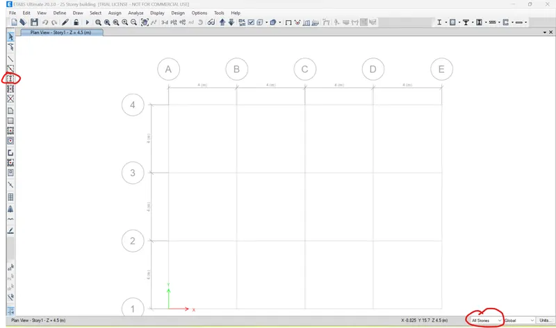
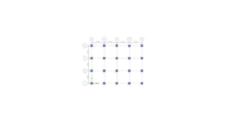
- Then for modelling the structure plan view is selected and for column modelling all storeys option is selected in the lower option box as the column runs straight from base to top storey and quick draw column option is selected and the columns are placed at every intersection points of the grids.
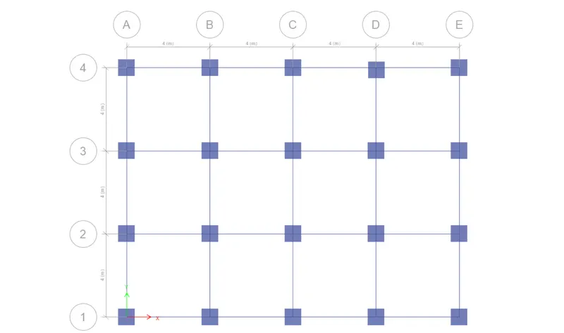
- For modelling of the beam initially plint level plan is selected and one story option is selected as it is not to be replicated in any of the storeys. Followed by that quick draw beam option is selected and the beams are drawn by selecting the grid lines between the columns.
- Then 1st storey plan view is selected and similar storey option is selected for modelling and using quick draw beam option all the grid lines are selected and the beams are drawn and are replicated in all storeys.
- For drawing of slabs, similar to beam 1st storey plan view and similar storey option is selected and all the grids are selected and the slabs are created.Thus the structure is completed and the 3d view is also presented in the image.
- After modelling the structure the next step is to define loads and combinations of the same and to apply it on the structure.
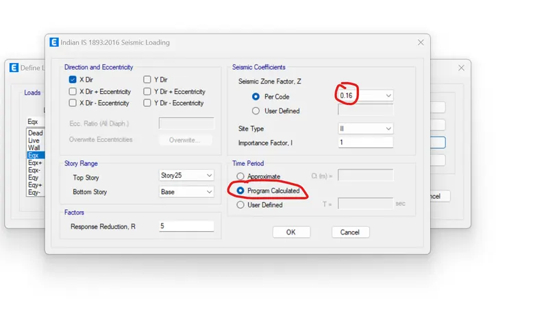
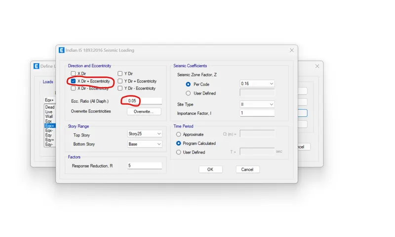
- Under define command in the ribbon load patterns option is selected and the loads are defined and added using the add load option.The loads predefined are dead,live and the defined loads are wall load defined under super doad and Earthquake loads in x and y direction defined under the seismic load and the code provision given is IS1893.
- Using Modify lateral load option zone factor,soil,type is defined as per the given conditions.
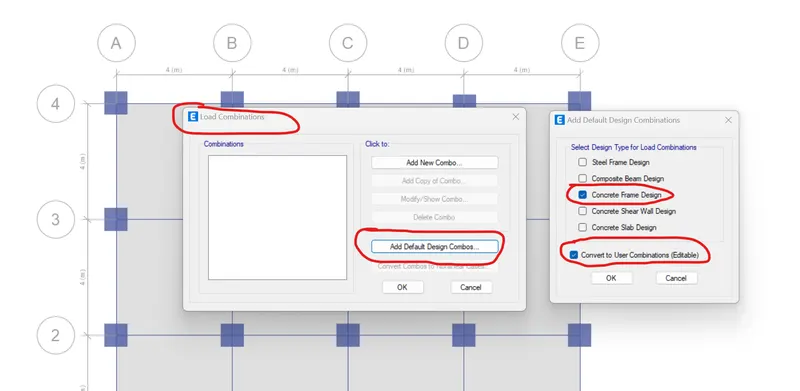
- Then load combination is defined using the load combination option under define command in the ribbon.
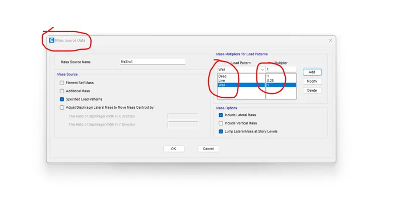
- Then mass source is defined for earthquake using mass source option in the define command the mass defined are full dead and super dead load and 25% of live load as per code provisions.
- After defining the loads the next step is to assign loads to the structure.
- Assign tab option is used for assigning loads to the elements of the structure.
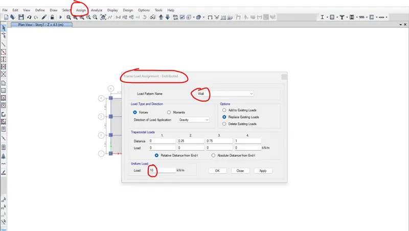
- For beams, frame loads and uniform option are selected to distribute the loads uniformally and the loads assigned are wall loads as beams carry the superdead load of walls
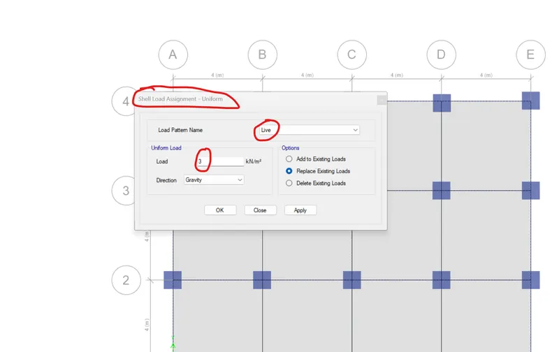
- For slabs, shell loads and uniform option are selected under the assign tab and the loads assigned are live loads as slabs carry the live load
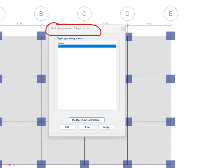
- For defining the centre of mass diaphragm option is used under the define tab.
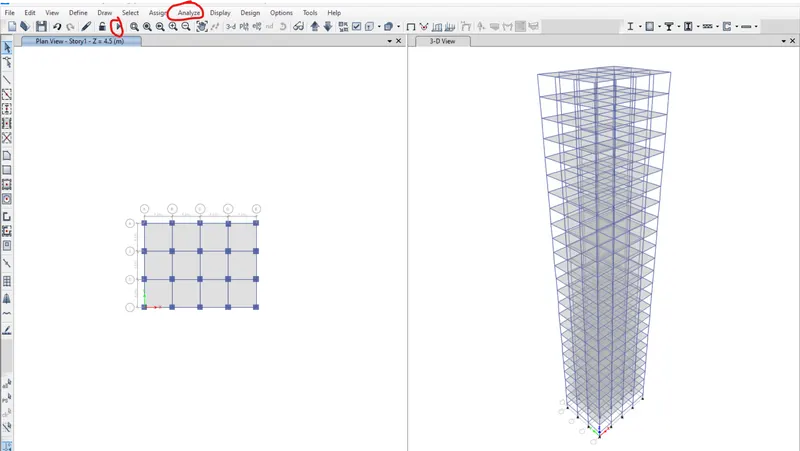
- Finally after assigning all the loads to the analysis of the structure is done using the run analysis option under the analyze tab.
- The results are viewed using the show tables option under the display tab.
Results:
- Check if the translational fundamental natural period of vibration in both the x and y direction is approximately: Tx1Tx1= 4.4 second Ty1Ty1= 4.2 second
This check will help confirm if modelling is done correctly. Some deviations from the above values is possible (± 2%). But any major deviation will suggest an error in modelling.
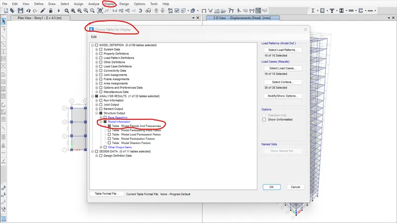
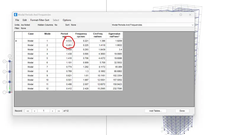
From the analysis results it can be seen that the fundamental natural period of vibration in both x and y direction are Tx1=4.5s and Ty1=4.4s which are more or less equal to the desired results.
- Check if the following provision in Table 5 of IS 1893 (part 1) – 2016, on torsional irregularity satisfied:
The natural period corresponding to the torsional mode of oscillation must be less than the two fundamental translational modes of oscillation along each principal plan directions.
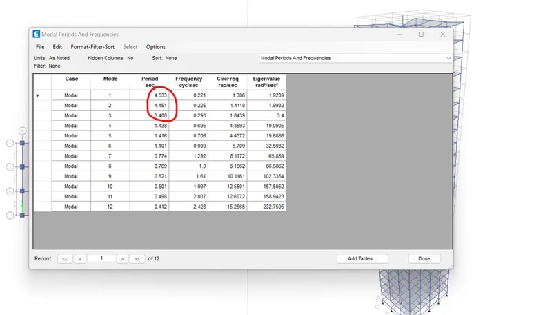
From the table it can be clearly seen that the torsional mode of oscillation is 3.4s which is less than the two fundamental translational mode of oscillation.
- Check if the two provisions of clause 7 in Table 6 (shown below) of IS 1893 (part 1) – 2016, regarding vertical irregularity is satisfied
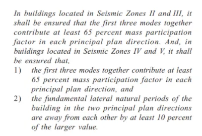
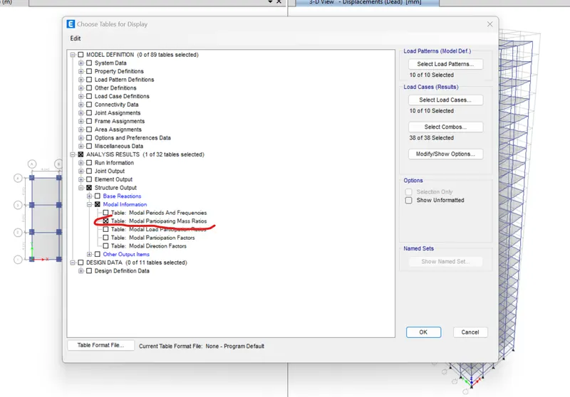
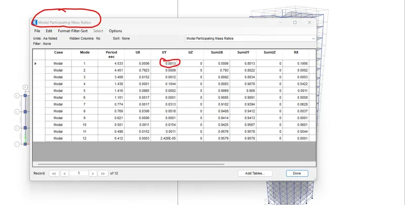
From the table it can be seen that the modal participating ratio of 1st mode itself 80% hence satisfies the first criteria of clause 7 Table 6.
It can be seen from the results that the Tx1 and Ty1 are 4.5s and 4.4s which are not far away by 10% and does not satisfy the 2nd criteria.
- Check if provision on inter-storey drift limitations in clause 7.11.1.1 satisfied. Please note that this check is for Serviceability Limit State and hence is for situation when stucture is subjected to unfactored seismic base shear
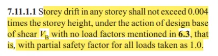
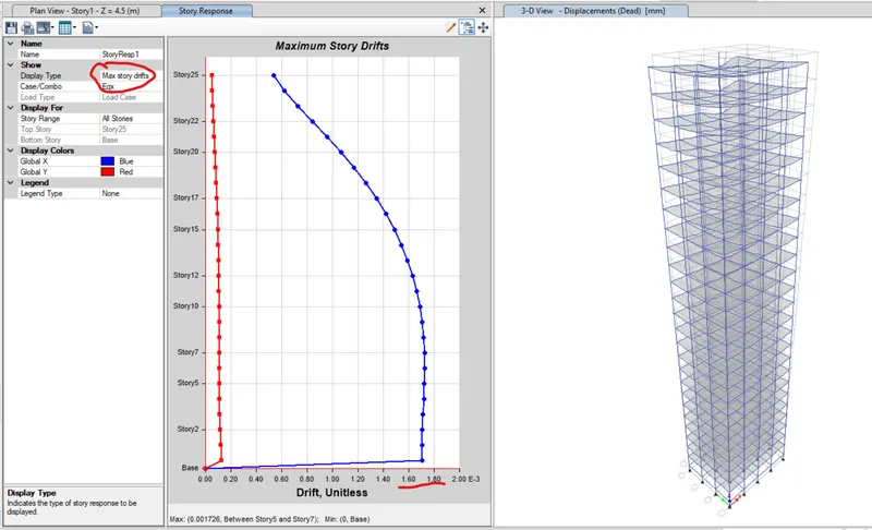
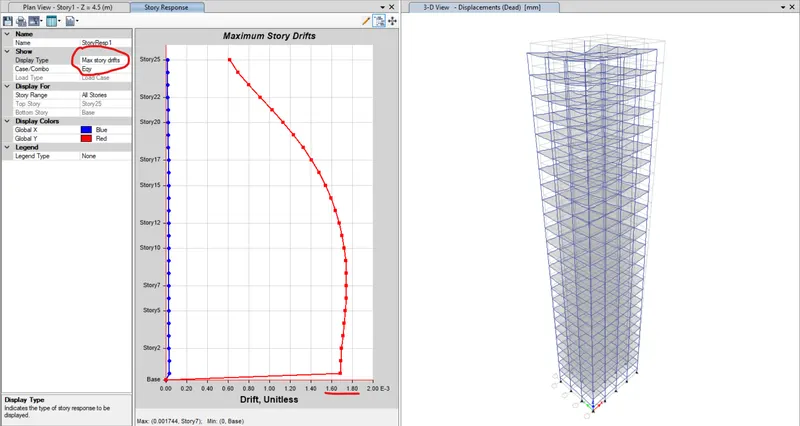
From the above image it can be concluded that the storey drifts are not exceeding 0.004 times the height of the building and satisfies the condition.
Hence a 25 storey building has been modelled and analysed sucessfully.