Modelling of 25 storey building with the specified properties using ETABS
AIM :
- TO KNOW MODELLING OF HIGH RISE BUILDING IN ETAB's SOFTWARE.
- TO VERIFY SEISMIC CODE REQUIREMENTS FROM ETAB's SOFTWARE.
PROCEDURE :
STEP -1
- Open ETABS.
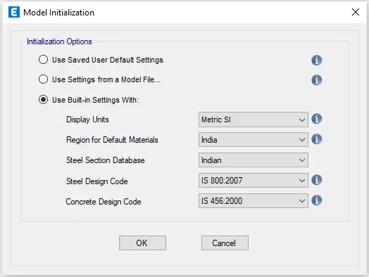
- Go to file menu and select new model, a pop up window of model initialization will be opening.
- Select use built in settings.
- Select display units as Metric SI, Steel section data base as Indian, Steel design code as IS 800:2007, concrete design code as IS 456:2000.
- Select OK.
STEP -2
- A new window of new model quick templates will be appearing.
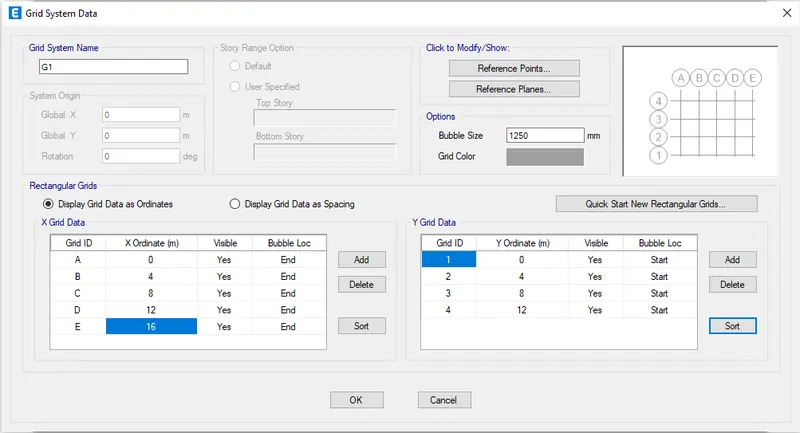
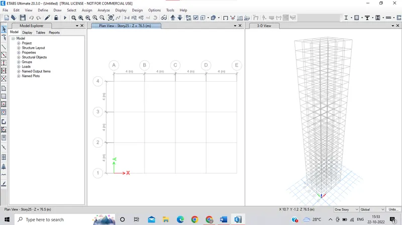
- Select the grids and customise grids.
- Set X grid data at spacing of 4m, and number of grids is 5.
- Set Y grid data at spacing of 4m, and number of grids is 4.
- Click OK
STEP-3
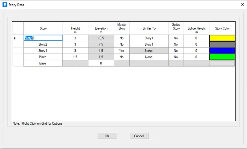
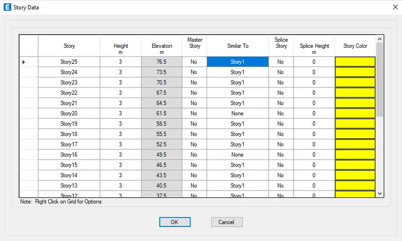
- Now select the option custom story data and select edit storey data.
- Select plinth height as 1.5m, and height of storey as 3m.
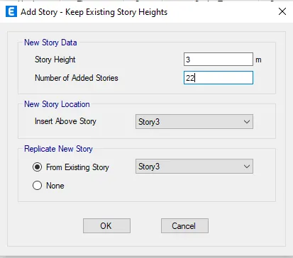
- Add storey and make total number of story as 25.
- Keep master storey 1 as yes.
- Click OK.
STEP -4
- Defining the properties of elements.
- Go to define and select material properties.
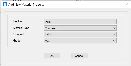
- Select grade of concrete as M30.
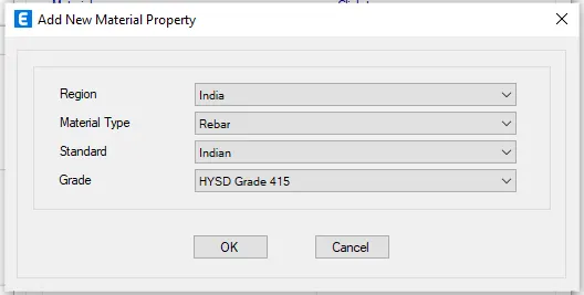
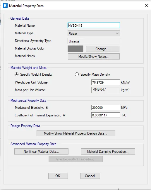
- Select steel as HYSD 500and HYSD 415 steel.
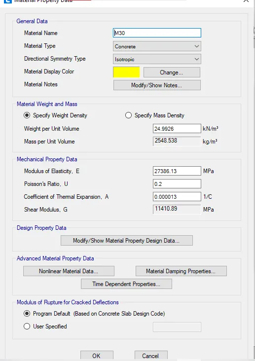
- PROPERTY OF CONCRETE
- CONCRETE MATERIAL PROPERTY DATA
- PROPERTY OF STEEL
STEP-5
- Defining beam column properties.
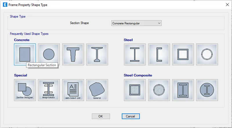
- Go to define tab, section properties and frame sections.
- FRAME PROPERTY TAB
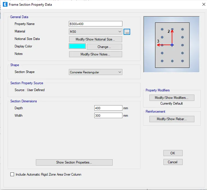
- BEAM DETAILS
- BEAM REINFORCEMENT DETAILS
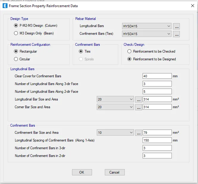
- COLUMN PROPERTIES
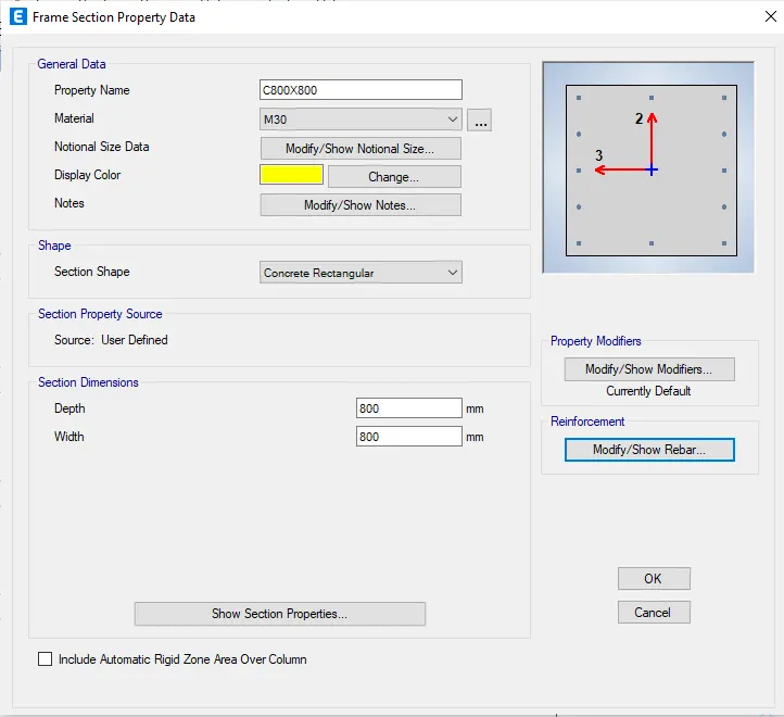
- COLUMN REINFORCEMENT DETAILS
STEP-6
- Defining slab properties.
- Go to define tab, section properties and slab sections.
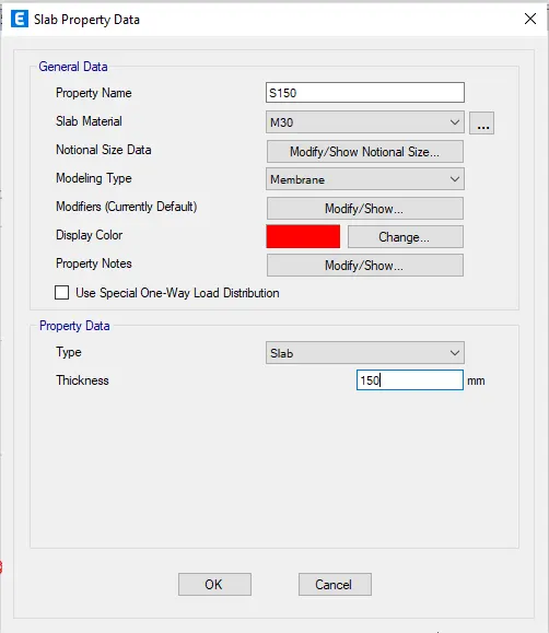
- SLAB PROPERTY DATA
STEP-7
- Assigning loads on the structure.
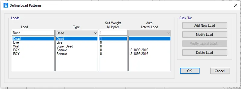
- Select define, load patterns and enter the load patterns as shown in the image.
- DEFINING LOAD PATTERNS
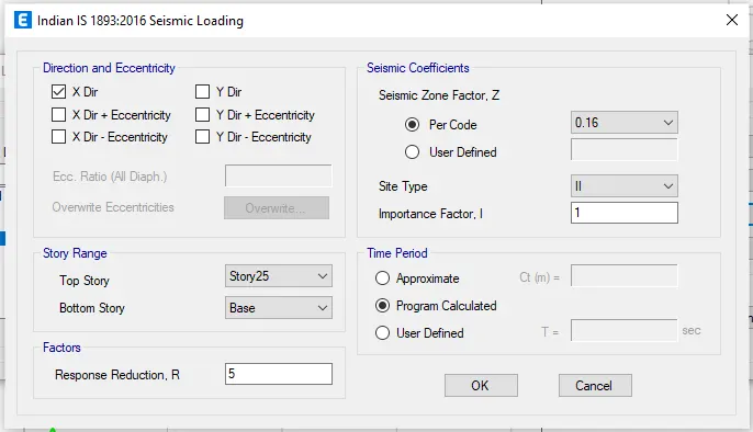
- Modifying the seismic lateral loads
STEP-8
- Assigning mass source to model.
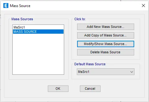
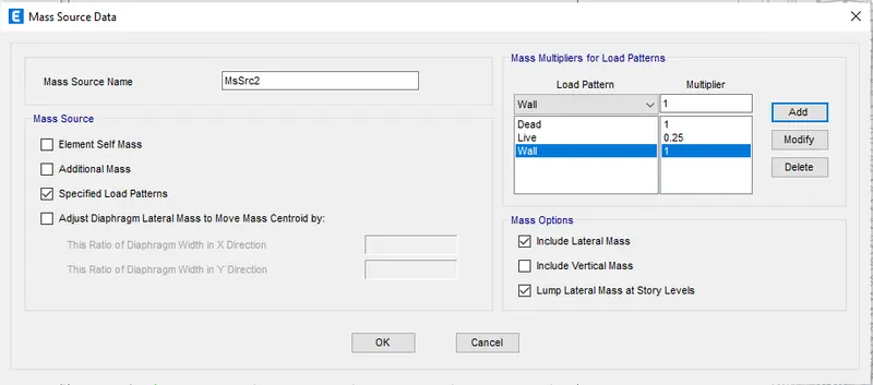
- Go to define tab select mass source and enter the details as shown in the image.
- MASS SOURCE DATA
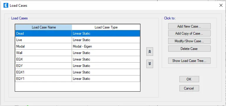
- CHECKING THE LOAD CASES WE APPLIED
STEP-9
- Generating load combinations.
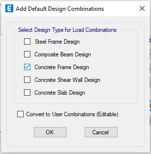
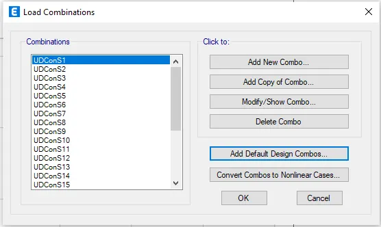
- Select define tab- load combinations- add default- concrete frame- convert to editable.
- LOAD COMBINATION DATA
STEP-10
- Drawing of beams and columns.
- In the left side of the draw panel select the option quick draw column.
- Place columns on the grids
- For drawing of beams select the option quick draw beams in the draw panel and place the beams.
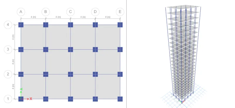
- DRAWING OF BEAM AND COLUMN
STEP-11
- Drawing of slab.
- In the left side of the draw panel select the option quick draw floor.
- Place slabs between the grids
STEP-12
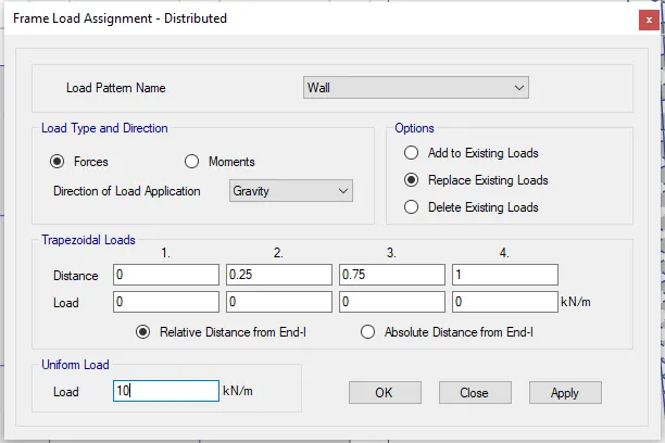
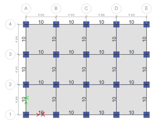
- Assigning load on beam as brick wall load.
- Apply load of 10KN/M.
- BRICK WALL LOAD PATTERN TYPE
- BRICK WALL LOAD APPLIED ON BEAMS
STEP-13
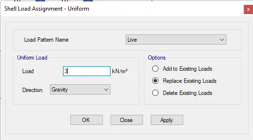
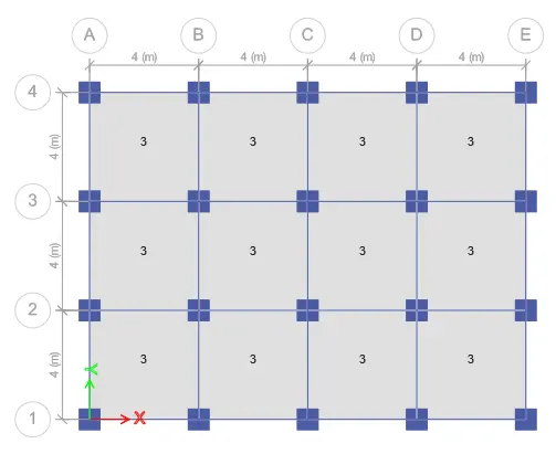
- Assigning live loads.
- Go to assign tab and select shell loads , uniform and assign load of 3KN/M^2
STEP-14
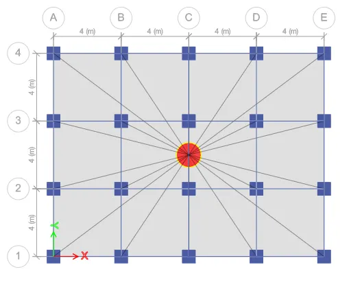
- Assigning diaphragms to the model.
- Go to assign tab select shell, select diaphragms and select D1.
- Apply the diaphragms.
STEP-15
- Running the analysis.
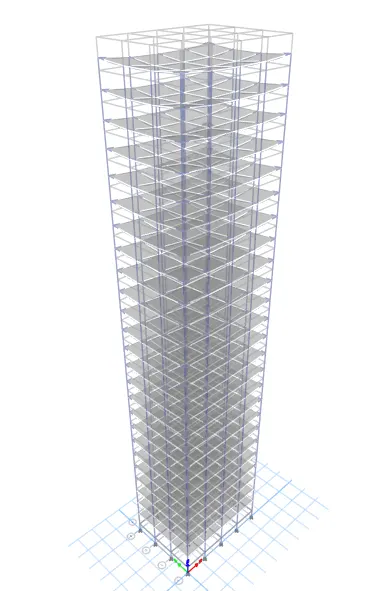
AFTER RUNNING THE ANALYSIS
STEP-16
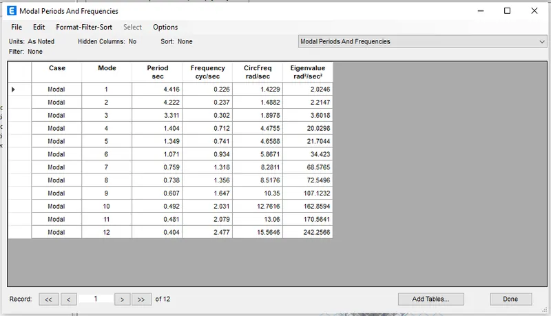
- Modal results.
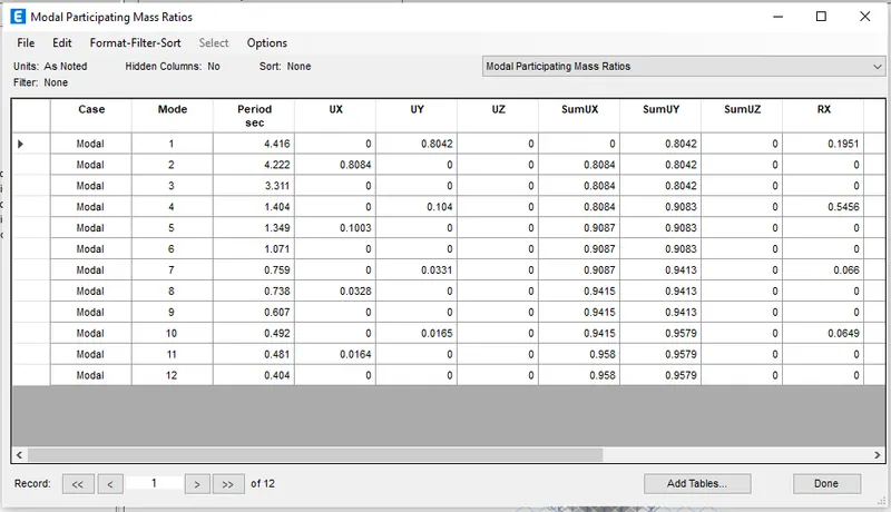
- Select display- show tables- structure output- modal information- modal participation mass ratios.
- A table will be appearing on the screen.
MODAL PERIODS AND FREQUENCIES RESULT TABLE
MODAL MASS RATIO RESULT TABLE
STORY RESPONSE-EQX DIERECTION

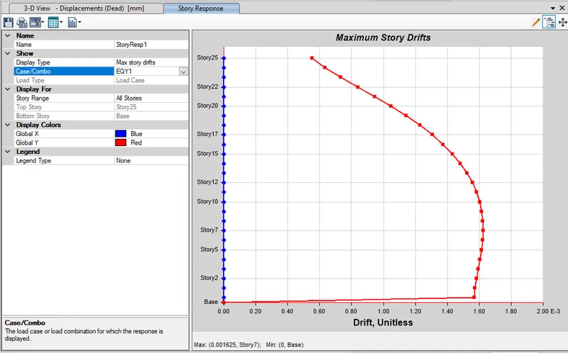
STORY RESPONSE-EQY DIRECTION
RESULTS :
FROM ABOVE ANALYSIS RESULT TABLE WE GET THE ANWERS AS BELOW:
| CRITERIA | DESIRED SOLUTION | EXERCISE RESULT | |
| FUNDAMENTAL TRANSITIONAL NATURAL PERIOD | X-DIRECTION | 4.4 SECONDS | 4.41 |
| Y-DIRECTION | 4.2 SECONDS | 4.22 | |
| TORSIONAL IRREGULARITY |
IS 1893-2016TABLE-5 |
TORSIONAL MODE TIME PERIOD SHOULD BE LESSER THA X & Y DIRECTION TIME PERIODS | YES |
| VERTICAL IRREGULARITY |
IS 1893-2016 TABLE 6 |
First three modes together should contribute at least 65% in mass participation factor in each principle direction | YES |
| Fundamental lateral natural periods in two principle plane directions are away from each other by at least 10% | NO | ||
| INTER-STOREY DRIFT | IS 1893-2016 CLAUSE 7.11.1.1 | Storey drift shall not exceed 0.004 ti,es the storey height base shear with no load factors (4X10^-3) | YES |