Modelling of 25 storey building with the specified properties using ETABS
AIM:
Objective of the project is to model & analysis of 25 storey building using Etabs for the given specification and to verify the results as per the IS 1893 codal provision.
Procedure:
Step:1
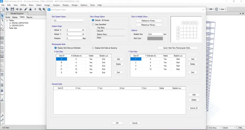
EditDropDown (tool bar)> Modify/Show Story Data... (button)> Modify/Show Grid System... (button)
Using the Edit Story and Grid System Data, the structural base grid system is assigned for modelling reference.
Step:2
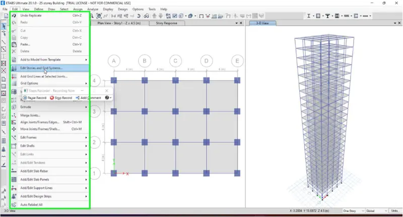
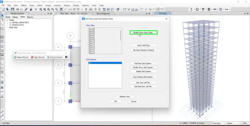
EditDropDown (tool bar)> Modify/Show Story Data... (button)> Story Data
Using the Edit Story and Grid System Data, required number of storey details are added.
Step:3
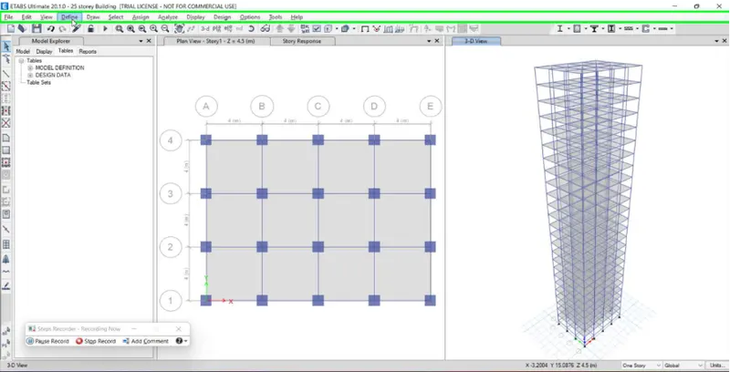
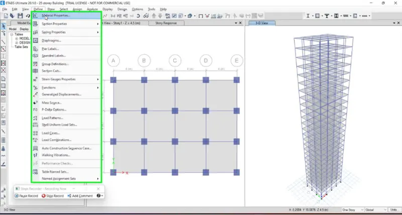
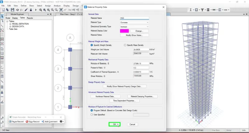
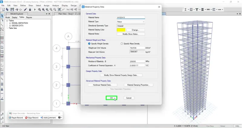
Define DropDown (tool bar)> Define Materials> Modify/Show Material... (button)>Concrete and Steel property.
Using Define Materials concrete of M30 grade & Steel of Fe500 grade is defined.
Step:4
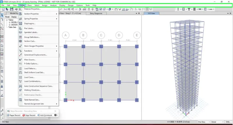
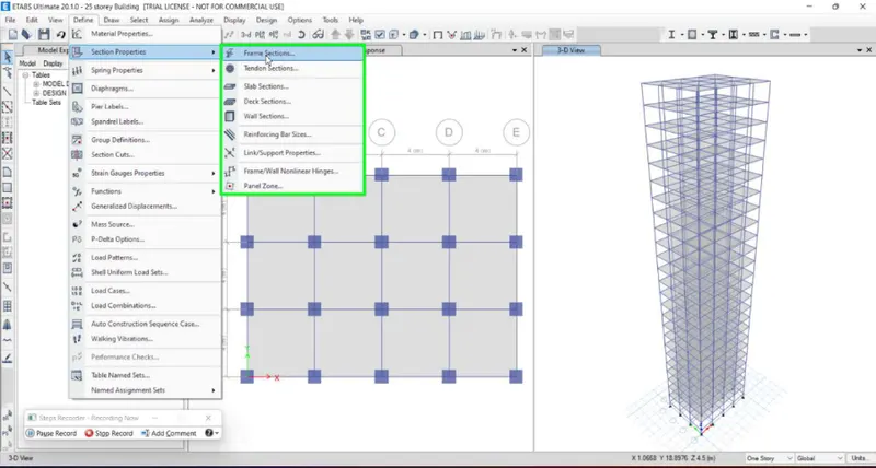
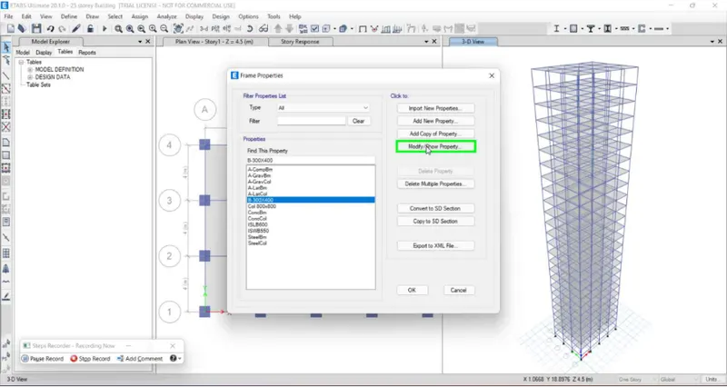
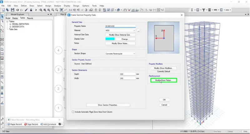
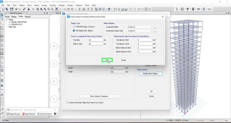
Define>Section Properties Drop Down (tool bar)> Frame Properties> Modify/Show Property... (button)> Modify/Show Rebar... (button)
Using the Frame Properties tools the Beam of size 300x400mm created and the rebar property are assigned.
Step:5

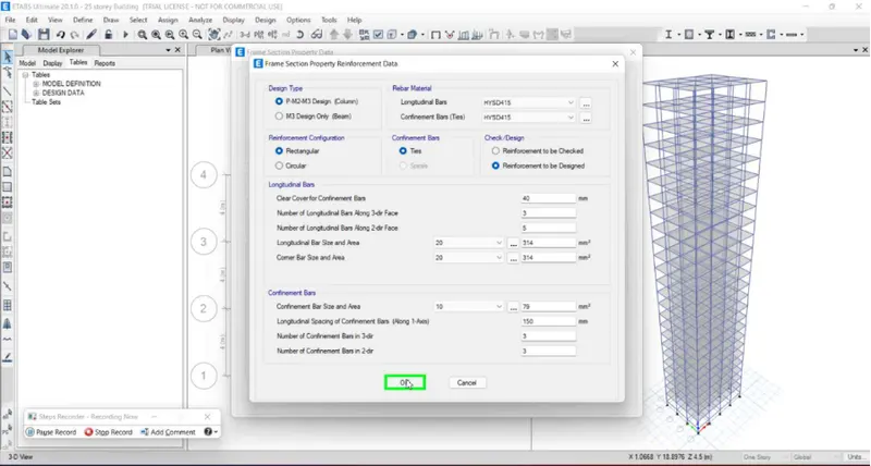
Define>Section Properties Drop Down (tool bar)> Frame Properties> Modify/Show Property... (button)> Modify/Show Rebar... (button)
Using the Frame Properties tools the Column of size 800x800mm created and the rebar property also assigned.
Step:6
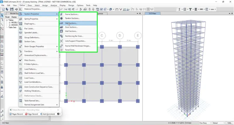
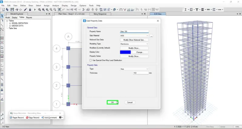
Define>Section Properties Drop Down (tool bar)> Slab Properties> Modify/Show Property... (button)>Modelling type>Membrane
Using the Slab Properties tools the slab size 150mm created and the modelling type is assigned as Membrane type.
Step 7:
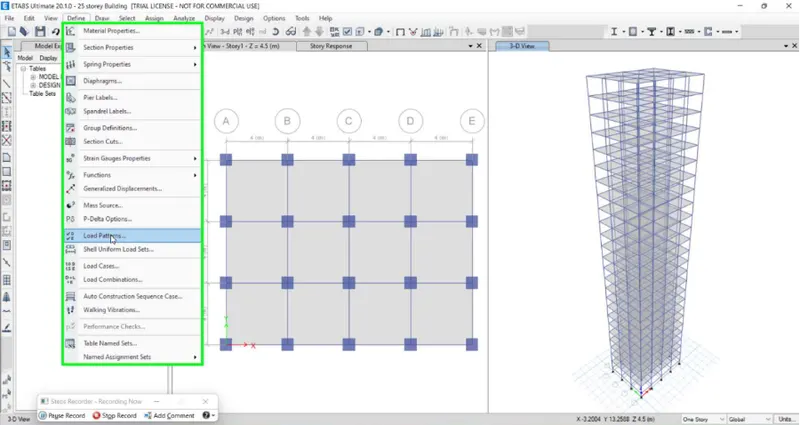
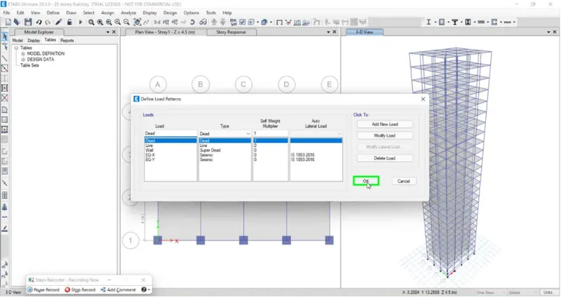
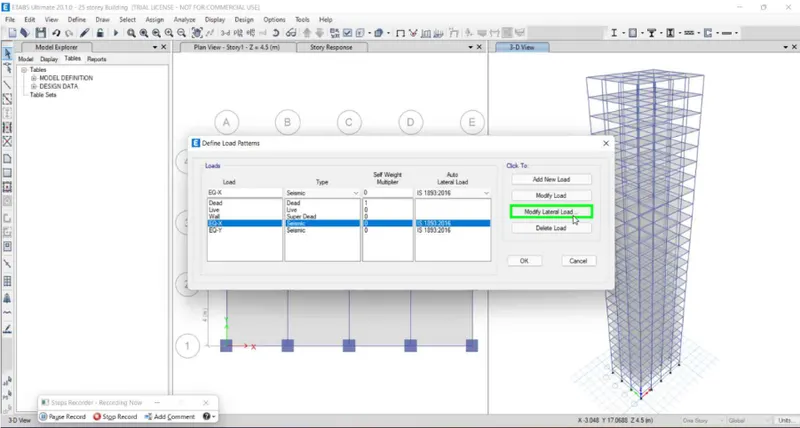
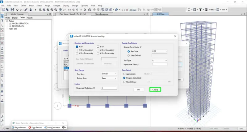
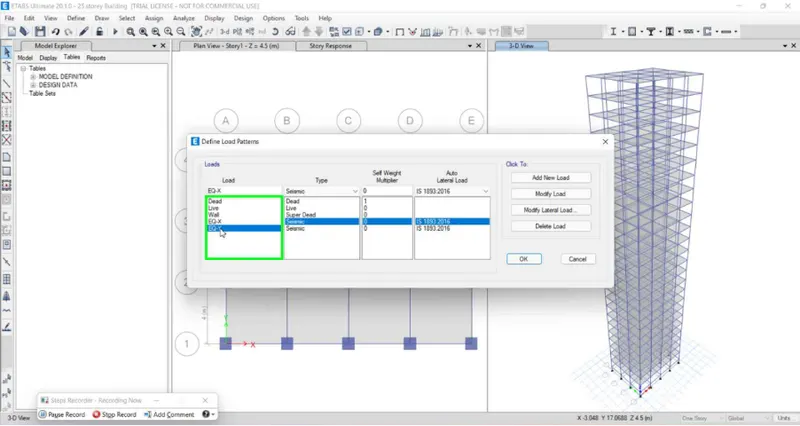
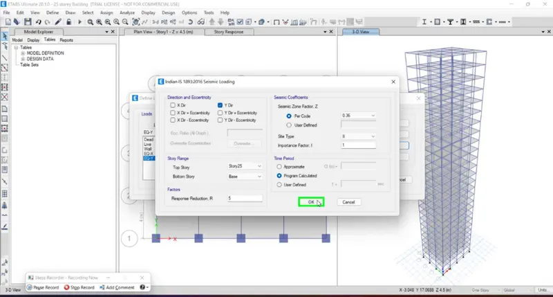
Define Dropdown (tool bar)> Define Load Patterns> Modify Lateral Load... (button)> Indian IS 1893:2016 Seismic Loading
The load patterns for gravity load and lateral loads are defined as per the IS 1893-Codal provision.
Step 8:
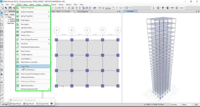
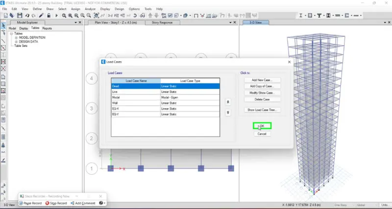
Define Dropdown (tool bar)> Load Cases
Using the define load cases the Dead load, Live load, imposed load (wall load) and lateral load cases are defined.
Step:9
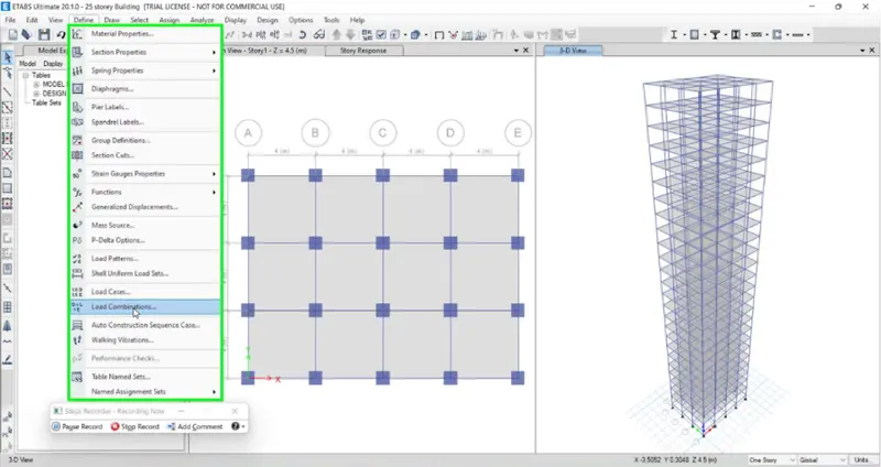
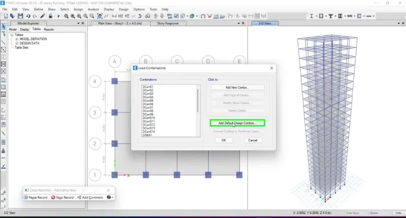
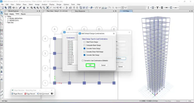
Define Dropdown (tool bar)> Load Combinations >Add Default Design Combos... (button)> Concrete Frame Design (check box)> Concrete Slab Design (check box)
Using the Load combination tool bar required combinations can be generated automatically by clicking the Add Default Design Combos... (button)
Step:10
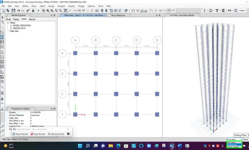
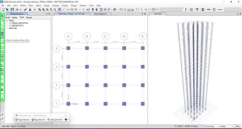
Using All Stories (list item), select all storey>Quick draw Column
By selecting all storey, column creating in master storey will be replicated to all storey. And the column locations are assigned.
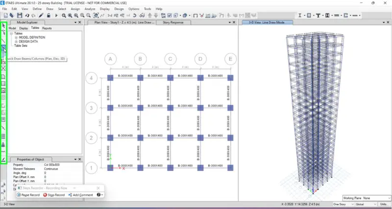
Using All Stories (list item), select all storey>Quick draw beams
By selecting all storey, Beams creating in master storey will be replicated to all storey. And the beams locations are assigned.
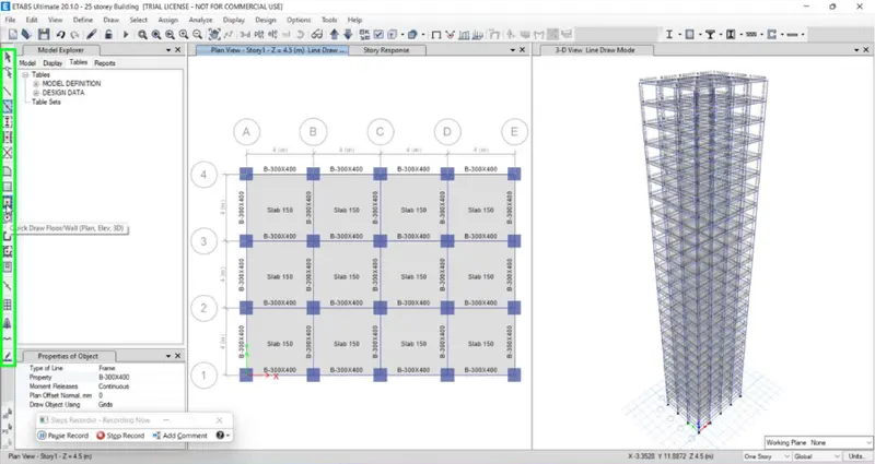
Using All Stories (list item), select all storey>Quick draw floors
By selecting all storey, framing creating in master storey will be replicated to all storey. And the floor locations are assigned. In all storey the floors are created except plinth level.
Step:11
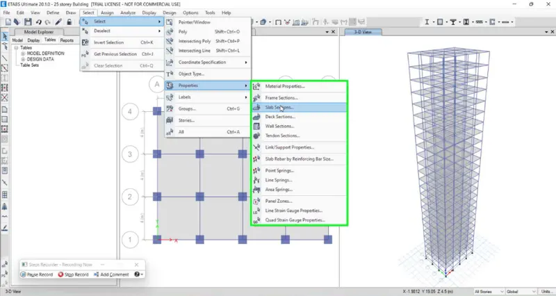
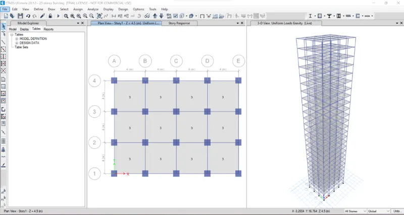
Select Dropdown (tool bar)> Properties Dropdown (tool bar)> "Slab 150 (list item)" in "Select by Slab
Assign Loads Dropdown (tool bar)> Shell Loads Dropdown (tool bar)> Shell Load Assignment - Uniform
By selecting all floors, uniform floor load for Live load 3kN/m2 is assigned in all floor levels.
Step:12
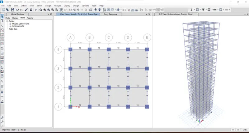
Select Dropdown (tool bar)> Properties Dropdown (tool bar)> "Beam 300x450 type" in "Select by frame
Assign Loads Dropdown (tool bar)> Frame Loads Dropdown (tool bar)> Distributed load
After selecting all beam using select by type, then assigning 10kN wall load in all floors including parapet wall in terrace as per given data.
Step:13
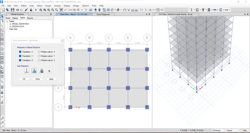
Assign>joint>Restrains>pinned
Using the plan selection menu go to the base level and assign the pinned support to the base of the column in base level.
Step:14
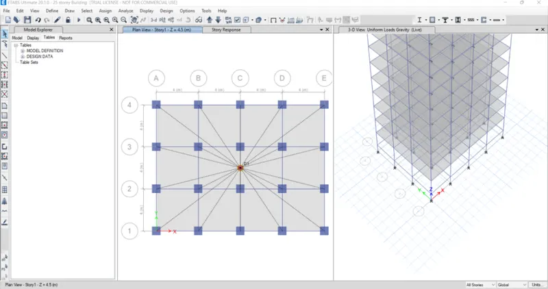
Select Dropdown (tool bar)> Properties Dropdown (tool bar)> "Slab 150 (list item)" in "Select by Slab
Assign>Shell>Diaphragms
By selecting all the floors and then assigning the Diaphragms, for assigning the centre of mass.
Step:15
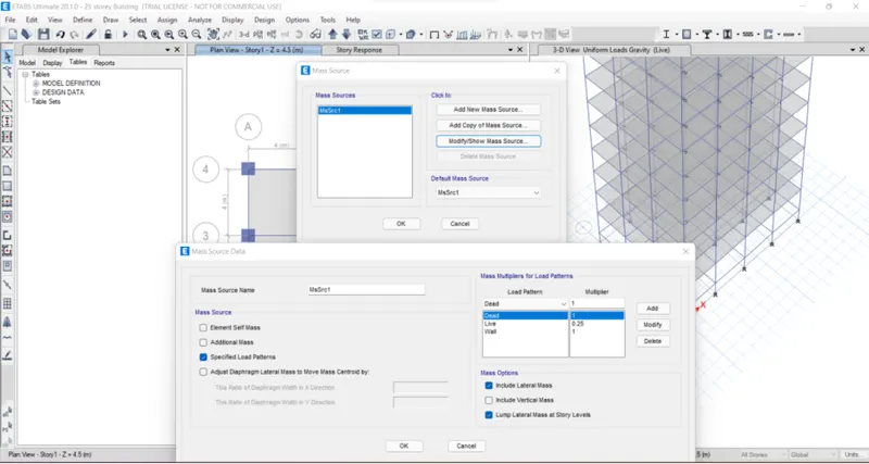
Define>Mass source>Modify/show mass source
Mass source of the building is assigned to calculate the base shear of the building is assigned. Where 100% dead load and imposed load applied and 25% of live load is considered as per the IS codal provisions.
Step:16
Analyze>Check model
To check the model whether any errors and warnings are there and rectify the error if any.
Step:17
Analyze>Run analsysis
After the model run, checked the BMD & SFD of the system and the deflection of the building for the correct behaviour.
Step:18
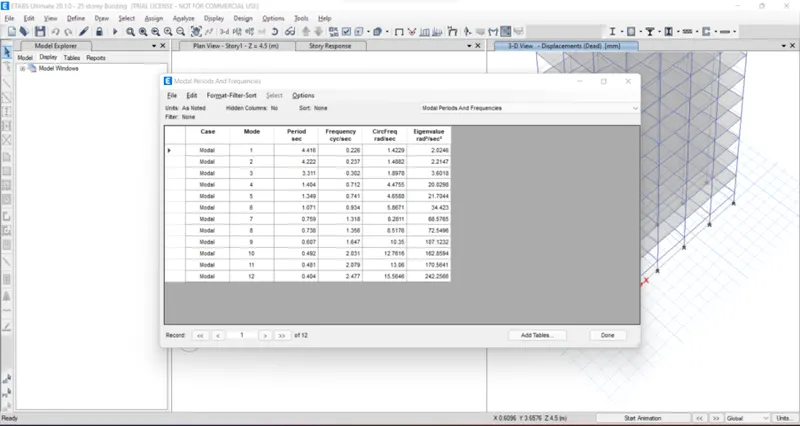
Display tool bar>Show tables>Analysis results drop down>Structural output>Modal information>Modal periods & Frequencies
For Fundamental Mode-1 Y & X direction values obtained from the table is
Translation X-Direction,Tx1=4.416
Translation Y-Direction Ty1=4.22 which is similar to the checking value.
(translational fundamental natural period of vibration in both the x and y direction is approximately: Tx1= 4.4 second Ty1= 4.2 second)
Step:19
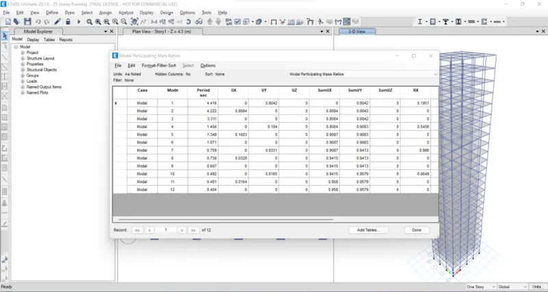
Display tool bar>Show tables>Analysis results drop down>Structural output>Modal information>Modal participation mass ratios
In the above table, Model-1 translation & Torsional Degree of freedom,
For Natural time period,
Tx1=4.222sec
Ty1=4.416sec
Txy1=3.311sec
Torsional irregularity:
This shows that the torsional mode time period 3.311 is lesser than the X and Y direction time period as per the IS Code-1893-2016-part-1-Table-5
Mass irregularity:
The mass participation ratio for 3 modes,
Tx1=0.8042
Tx2=0.8084
Tx3=0
Sum of mode mass ratios for the 1&2 mode is greater than 65% of building mass as pe the Etabs analysis as per IS code 1893-2016-Part-1-Table-6-Clause-7.
The Fundamental natural period difference is not greater than 10%, and does not satisfy the minimum requirements.
Step:20
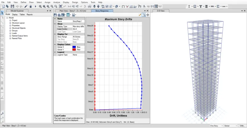
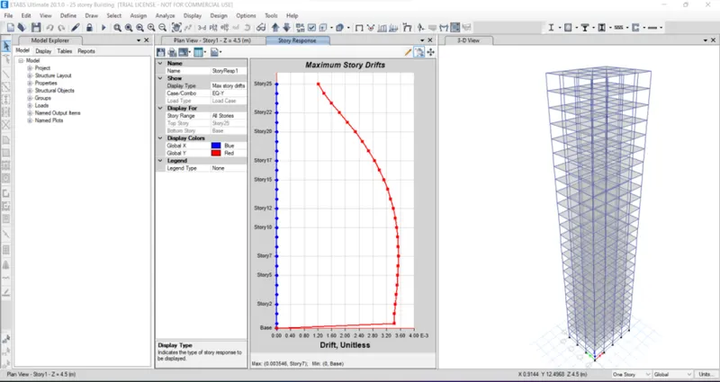
Display>Storey response plot>Display type (Max story drift)>Case(Eqy)
As p0er IS code 1893-2016-Clasue7.11.1.1, max inter storey drift is to limit below 0.004 between each storey height. (for base shear with no gravity loads)
Etabs result values of both EQ-X & EQ-Y direction the inter storey drift value
is below 4x10E-3.
Conclusion:
Modelling and analysis is done for the 25storey building for the required specifications.
All the requirements are satisfied as per the IS standard. Except the Fundamental natural period difference is not greater than 10%, criteria.