Modelling and simulation of flow through a flowbench
Aim: To create a 3D model of a flow bench and run flow analysis and examine how mass flow rate depends on the valve lift.
Theory:
Valve lift determines the mass flow rate in the combustion chamber. As the valve lift increases the mass flow rate also increases. The best way to visualize this is using the flow bench technique. This project helps to visualize how the mass flow rate increases as the valve lift increases.
Procedure:
- Firstly, started designing the engine valve geometry
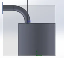
- The main important step before starting the flow simulation is to constrain the values of the valve.
- Then created a new flow simulation and provided the boundary conditions for the problem
- Used total pressure BC at the inlet and static pressure BC at the outlet.
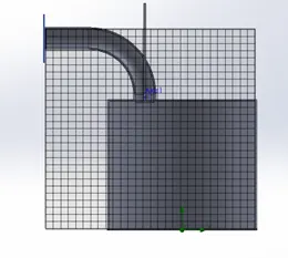
- Refined the mesh using local mesh at throat and valve geometry to get more refined results.
- Inserted the necessary goals and plots required for the analysis
Results:
- As the grid size decreases and the number of grids increase the accuracy of the results also increases. But increasing the number of grids also results in heavy computational time. So, the grid sizing needs to be chosen according to the analysis. In this project the main analysis is for the valve lift i.e., the main emphasis needs to be on the valve and throat reason. For this reason, I have created a local mesh at the region of the throat for better accuracy of the results and overall, less computational time.
velocity contours for different valve lifts
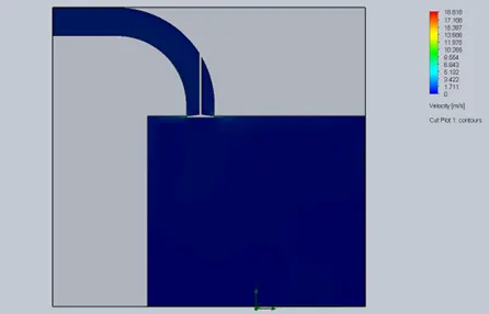
Valve lift at 0.0015m
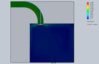
Valve lift at 0.00195m
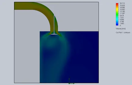
Valve lift at 0.00375
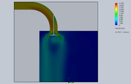
Valve lift at 0.00735
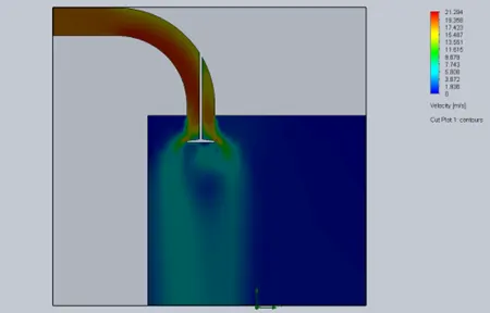
Valve lift at 0.00915
- From the above results as the valve lift increases the velocity of the flow increases and the mass flow rate also increase.
|
Valve Lift |
Mass flow rate |
|
0.00015 |
-0.0925 |
|
0.00195 |
-0.8429 |
|
0.00375 |
-1.1283 |
|
0.00555 |
-1.2983 |
|
0.00735 |
-1.3772 |
|
0.00915 |
-1.4139 |
- The negative sign represents that the flow is exiting from the outlet
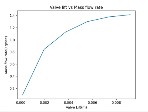
The above graph represents the relationship between the valve lift and the Mass flow rate which we have discussed before. From the results, it is easy to visualise how the velocity and the mass flow rate increases as the valve lift increases.