Micro-Controllers
Target:-
- To know about the communication of the HEVs with each other.
- write pseudocode about the speed performance
- explains about the microprocessor.
Objective:-
- What is the need for communication within the charger, battery pack, and motor drive?
- Pseudocode is an informal way of programming description that does not require any strict programming language syntax or underlying technology considerations. It is used to create an outline or a rough draft of a program and summarise a program's flow.
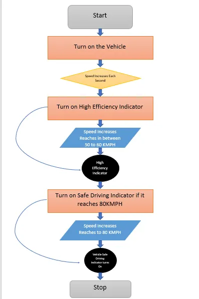
Write a pseudo code for displaying speed on the digital dashboard as per the below conditions.
Update displayed speed every second, Turn on high-efficiency indicator between 50 to 60 kmph, Turn on safe drive indicator above 80 kmph
- a.) What are the factors affecting the selection of microprocessors/microcontrollers?
b.) Explain the architecture of an 8-bit microcontroller(8051 or any other type can be considered). List the applications for the same.
c.) Explain the different types of transmission(serial communication) modes with the help of real-time examples.
Theory:-
- BSM
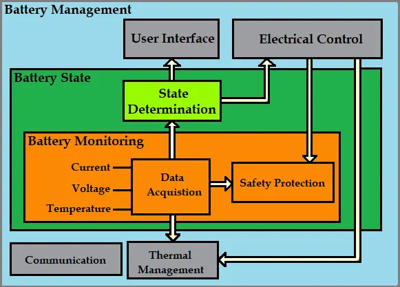
The communication between the battery, charger and motor drive is also known as the battery management system. Communication is one the most essential part of the HEVs as we all know that the battery is consisting of many cells and they are very highly or densely packed with each other and normally in thr case of HEVs they are having a higher energy density as much as 100-265Wh/kg, so it is much more important to know the importance of BMS.
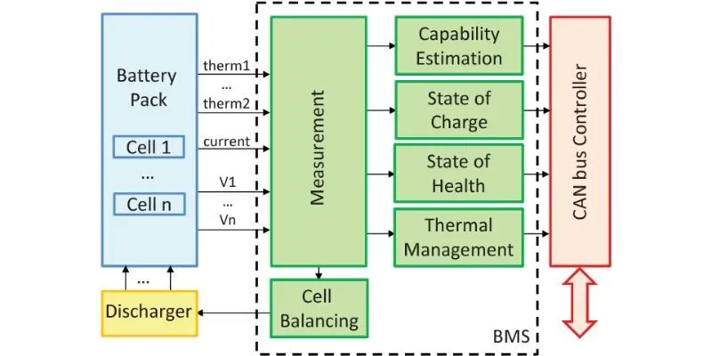
In BMS there are so many things are covered like measurement of battery which means the capability of the battery is been estimated, it helps in calculation of the state of charge and as well as the health with all this there are also thermal issues which are generally more problematic to the whole system and this is the major disadvantage of the battery-operated vehicle so there should also be thermal management for the cooling of the system. So, everything has to do between them so it is required for the communication between the battery, charge and the motor drive.
Battery thermal management systems can be either passive or active, and the cooling medium can either be air, liquid, or some form of phase change. Air cooling is advantageous in its simplicity. Such systems can be passive, relying only on the convection of the surrounding air, or active, utilizing fans for airflow. Commercially, the Honda Insight and Toyota Prius both utilize active air cooling of their battery systems. The major disadvantage of air cooling is its inefficiency. Large amounts of power must be used to operate the cooling mechanism, far more than active liquid cooling. The additional components of the cooling mechanism also add weight to the BMS, reducing the efficiency of batteries used for transportation.
Liquid cooling has a higher natural cooling potential than air cooling as liquid coolants tend to have higher thermal conductivities than air. The batteries can either be directly submerged in the coolant or the coolant can flow through the BMS without directly contacting the battery. Indirect cooling has the potential to create large thermal gradients across the BMS due to the increased length of the cooling channels. This can be reduced by pumping the coolant faster through the system, creating a tradeoff between pumping speed and thermal consistency.
Electric vehicles run on very high voltage lithium-ion battery packs. Lithium-ion batteries have a higher energy density (100-265 Wh/kg) than other battery chemistries. These batteries come with the risk of catching fire under unusual circumstances. It is imperative to operate the EV batteries in pre-defined safe limits to ensure the safety of the user as well as the vehicle.
With the help of communication, BMS is responsible for the thermal management of the battery and monitors its temperature continuously. If required, BMS can adjust cooling and trigger other safety mechanisms to seize operations and minimize risk. E.g. Hyundai Kona Electric, if overheating of the battery pack is detected by the BMS, the vehicle’s power is automatically limited and the car is put in full-safe mode.
Overcharging of lithium-ion cells can also lead to thermal runaway and potentially an explosion. BMS continuously monitors the voltage of the pack as well as individual battery cells and controls the supply of the current to avoid overcharging. BMS can enforce the limits of the maximum charge or discharge according to temperature.
Through communication, BMS is responsible for optimising the performance of the battery pack. Lithium-ion batteries perform best when their State of Charge (SOC) is maintained between the minimum and maximum charge limits defined in the battery profile. Overcharging as well as deep discharging degrades the capacity of the battery, thereby shortening its life. At the time of charging BMS determines how much current can safely go in & communicates the same to the EVSE (Electric Vehicle Supply Equipment or the charger). During discharge of the battery, BMS would communicate to the motor controller to avoid cell voltages reaching too low. Vehicles can show corresponding alert to the user to charge the battery pack. The BMS also controls the recharging of the battery pack by generated energy through regenerative braking.
Individual cells in the battery pack can develop differences in capacity with time, which amplify with each charge/discharge cycle. This imbalance limits the amount of energy that can be derived from the battery also how much the battery pack can be charged. Cell balancing is needed to maintain the cells at equal voltage levels and maximize the capacity utilisation of the battery pack.
Measurement of the individual cell voltages by BMS indicates their relative balance and acts as a pointer to how much charge equalization is required. The BMS performs cell balancing by draining excess energy from cells that are more charged than others, through active and passive balancing techniques.
With the help of communication technology, BMS uses the collected data points (temperature, voltage, current) to estimate the State of Charge (SOC) & State of Health (SOH) of the battery pack. The SOC refers to the available energy in the battery & determines how far the vehicle can go before needing to charge. The SOH determines the current condition of the battery as compared to its original capacity and indicates the battery’s suitability for the application. Both SOC & SOH are presented as percentages. It also checks for anomalies in the parameters and behaviour of the cells and the battery pack. It stores the error codes and logs diagnostic information that helps fix any issues with the battery. BMS can either take necessary corrective actions or trigger failsafe mechanisms to preserve the health of the pack.
With the help of communication techniques, BMS is responsible for communicating with other ECUs in the vehicle. It relays the necessary data about the battery parameters to the motor controller to ensure the smooth running of the vehicle. In the case of AC charging the BMS communicates with the onboard charger to monitor and control the charging of the battery pack. For DC charging the communication link is directly established between the EVSE and the BMS. BMS communicates the required output voltage and current levels to the EVSE. & sends instructions to start and stop the charging process.
- the answer is in the solution
- the answer is as follows
-
The processing components used for embedded devices can be divided into two broad categories; Microcontrollers and Microprocessors.
Microcontrollers are small computing devices on a single chip that contain one or more processing cores, with memory devices embedded alongside programmable special and general-purpose input and output (I/O) ports. They are used especially in applications where only specific repetitive tasks need to be performed. Microprocessors on the other hand are general-purpose computing devices that incorporate all the functions of the central processing unit on a chip but do not include peripherals like memory and input and output pins like the microcontroller.
Although manufacturers are now changing a lot of things that are blurring the line between microcontrollers and microprocessors like the use of memory on chips for microprocessors and the ability of microcontrollers to connect to external memory, key differences still exist between these components and the designer will need to choose the best between them for a particular project.
Some of the factors in the design specification that needs to be considered before choosing between a microcontroller and a microprocessor are described below.
-
Processing Power:- Processing power is one of the main (if not the main) things to consider when selecting between a microcontroller and a microprocessor. It’s one of the main factors that tilt use for microprocessors. It is measured in DMIPS (Dhrystone Million of Instructions Per Seconds) and represents the number of instructions a microcontroller or microprocessor can process in a second. It is essentially an indication of how fast a device can complete a task assigned to it.
One other main implication of processing power that affects the choice between microprocessors and microcontrollers is the complexity or simplicity of things like User interfaces. It is a desirable thing these days to have colourful and interactive GUIs even for the most basic of applications. Most libraries used in creating user interfaces like QT require processing power as much as 80 – 100 DMIPS and the more animations, images and other multimedia contents to be displayed, the more the required processing power. they are generally more expensive compared to microcontrollers and will be overkill when used in certain solutions, for example using a 500 DMIPS microprocessor to automate a light bulb will make the overall cost of the product higher than normal and could ultimately lead to its failure in the market.
-
Interfaces:-The interface to be used to connect different elements of the product is one of the factors to be considered before choosing between a microcontroller and a microprocessor. It is important to ensure the processing unit to be used as the interfaces required by the other components.
From a connectivity and communications standpoint, for instance, Most microcontrollers and Microprocessors possess the interfaces required to connect to communication devices but when high-speed communication peripherals like the super speed USB 3.0 interface, multiple 10/100 Ethernet ports or Gigabit Ethernet port are required, things tilt in the direction of the Microprocessor as the interface required to support these are generally only found on them because they are more capable of handling and processing the large amounts of data and the speed at which those data are transferred.
The Impact of the protocols used for these interfaces on the amount of memory required for the firmware should be confirmed as they tend to increase memory requirements. It’s a general rule of thumb that a microprocessor-based design, be adopted for applications that require high-speed connectivity with a large amount of data being exchanged especially when the system involves the use of an operating system.
-
Memory:-These two data processing devices handle memory and data storage differently. Microcontrollers for instance come with embedded, fixed memory devices while microprocessors come with interfaces to which memory devices can be connected. Two major implications of this are;Cost --> The microcontroller becomes a cheaper solution since it does not require the use of an additional memory device while the microprocessor becomes an expensive solution to be adopted due to these additional requirements.
-
Limited Memory --> The fixed memory on the microcontroller makes the amount of data that can be stored on it limited. This is a situation not applicable to processors since they are usually connected to external memory devices. A good example of when this limitation can be a problem is when developing firmware for the device. Adding Additional kilobytes to the code size may require a change in the microcontroller to be used but if the design were based on a processor, we will only need to change the memory device. Thus Microprocessors offer more flexibility with memory. There are several other factors based on the memory to be considered, one of them is the start-up (boot) time. The Microprocessors for instance stores the firmware on external memory (Usually an external NAND or Serial Flash memory) and boot, the firmware is loaded into the DRAM of the processor. While this takes place within a couple of seconds, it might not be ideal for certain applications. The microcontroller on the other takes less time. Power
Power:- A final point to consider is power consumption. While Microprocessors have low power modes, these modes are not as many as the ones available on a typical MCU and with the external components required by a microprocessor-based design, it is slightly more complex to achieve low power modes. Asides from the low power modes, the actual amount of power consumed by an MCU is a whole lot lower than what a microprocessor consumes, because the larger the processing capability, the more the amount of power required to keep the processor up and running.
Microcontrollers, therefore, tend to find applications where ultra-low power processing units are required such as remote controls, consumer electronics and several smart devices where the design emphasis is on the longevity of battery life. They are also used where highly deterministic behaviour is needed.
Microprocessors on the other hand are ideal for industrial and consumer applications that require an operating system, are computation-intensive and require high-speed connectivity or a user interface with lots of media information.
-
-
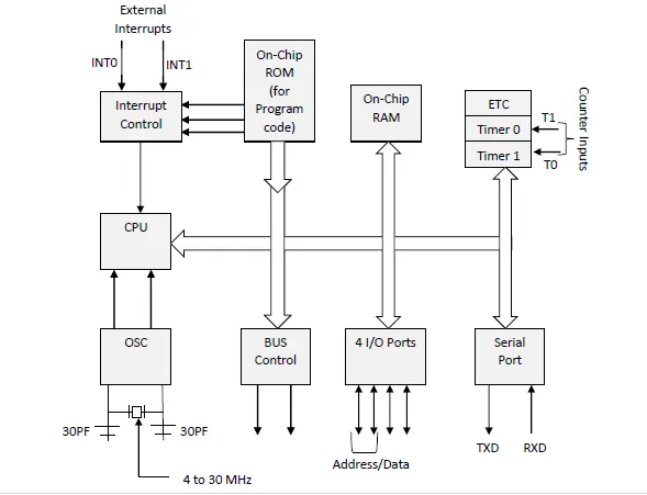
8051 microcontroller is designed by Intel in 1981. It is an 8-bit microcontroller. It is built with 40 pins DIP (dual inline package), 4kb of ROM storage and 128 bytes of RAM storage, 2 16-bit timers. It consists of are four parallel 8-bit ports, which are programmable as well as addressable as per the requirement. An on-chip crystal oscillator is integrated into the microcontroller having a crystal frequency of 12 MHz.
In the following diagram "1" the system bus connects all the support devices to the CPU. The system bus consists of an 8-bit data bus, a 16-bit address bus and bus control signals. All other devices like program memory, ports, data memory, serial interface, interrupt control, timers, and the CPU are all interfaced together through the system bus.
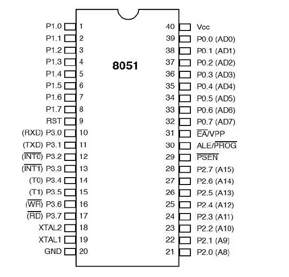
The pin diagram of the 8051 microcontroller looks as follows −
-
Pins 1 to 8 − These pins are known as Port 1. This port doesn’t serve any other functions. It is an internally pulled up, bi-directional I/O port.
-
Pin 9 − It is a RESET pin, which is used to reset the microcontroller to its initial values.
-
Pins 10 to 17 − These pins are known as Port 3. This port serves some functions like interrupts, timer input, control signals, serial communication signals RxD and TxD, etc.
-
Pins 18 & 19 − These pins are used for interfacing an external crystal to get the system clock.
-
Pin 20 − This pin provides the power supply to the circuit.
-
Pins 21 to 28 − These pins are known as Port 2. It serves as an I/O port. Higher-order address bus signals are also multiplexed using this port.
-
Pin 29 − This is PSEN pin which stands for Program Store Enable. It is used to read a signal from the external program memory.
-
Pin 30 − This is an EA pin that stands for External Access input. It is used to enable/disable external memory interfacing.
-
Pin 31 − This is ALE pin which stands for Address Latch Enable. It is used to demultiplex the address-data signal of the port.
-
Pins 32 to 39 − These pins are known as Port 0. It serves as an I/O port. Lower order address and data bus signals are multiplexed using this port.
-
Pin 40 − This pin is used to provide a power supply to the circuit.
8051 microcontrollers have 4 I/O ports each of 8-bit, which can be configured as input or output. Hence, a total of 32 input/output pins allow the microcontroller to be connected with the peripheral devices.
Pin configuration, i.e. the pin can be configured as 1 for input and 0 for output as per the logic state.
Input/Output (I/O) pin − All the circuits within the microcontroller must be connected to one of its pins except the P0 port because it does not have pull-up resistors built-in.
Input pin − Logic 1 is applied to a bit of the P register. The output FE transistor is turned off and the other pin remains connected to the power supply voltage over a pull-up resistor of high resistance.
Port 0 − The P0 (zero) port is characterized by two functions −
When the external memory is used then the lower address byte (addresses A0A7) is applied to it, else all bits of this port is configured as input/output.
When the P0 port is configured as an output then other ports consisting of pins with a built-in pull-up resistor connected by its end to 5V power supply, the pins of this port have this resistor left out.
Input Configuration
If any pin of this port is configured as an input, then it acts as if it “floats”, i.e. the input has unlimited input resistance and in-determined potential.
Output Configuration
When the pin is configured as an output, then it acts as an “open drain”. By applying logic 0 to a port bit, the appropriate pin will be connected to the ground (0V) and applying logic 1, the external output will keep on “floating”.
To apply logic 1 (5V) on this output pin, it is necessary to build an external pullup resistor.
-
Port 1
P1 is a true I/O port as it doesn’t have any alternative functions as in P0, but this port can be configured as general I/O only. It has a built-in pull-up resistor and is completely compatible with TTL circuits.
-
Port 2
P2 is similar to P0 when the external memory is used. Pins of this port occupy addresses intended for the external memory chip. This port can be used for a higher address byte with addresses A8-A15. When no memory is added then this port can be used as a general input/output port similar to Port 1.
-
Port 3
In this port, functions are similar to other ports except that logic 1 must be applied to the appropriate bit of the P3 register.
-
Pins Current Limitations
When pins are configured as an output (i.e. logic 0), then the single port pins can receive a current of 10mA.
When these pins are configured as inputs (i.e. logic 1), then built-in pull-up resistors provide very weak current but can activate up to 4 TTL inputs of LS series.
If all 8 bits of a port are active, then the total current must be limited to 15mA (port P0: 26mA).
If all ports (32 bits) are active, then the total maximum current must be limited to 71mA.
Interrupts are the events that temporarily suspend the main program, pass the control to the external sources and execute their task. It then passes the control to the main program where it had left off.
8051 has 5 interrupt signals, i.e. INT0, TFO, INT1, TF1, RI/TI. Each interrupt can be enabled or disabled by setting bits of the IE register and the whole interrupt system can be disabled by clearing the EA bit of the same register.
-
-
Data Transmission mode defines the direction of the flow of information between two communication devices. It is also called Data Communication or Directional Mode. It specifies the direction of the flow of information from one place to another in a computer network.
In the Open System Interconnection(OSI) Layer Model, the Physical Layer is dedicated to data transmission in the network. It mainly decides the direction of data in which the data needs to travel to reach the receiver system or node.
So, in this blog, we will learn about different data transmission modes based on the direction of exchange, synchronization between the transmitter and receiver, and the number of bits sent simultaneously in a computer network.
The data transmission modes can be characterized in the following three types based on the direction of exchange of information:
- Simplex
- Half-Duplex
- Full Duplex
The data transmission modes can be characterized in the following two types based on the synchronization between the transmitter and the receiver:
- Synchronous
- Asynchronous
The data transmission modes can be characterized in the following two types based on the number of bits sent simultaneously in the network:
- Serial
- Parallel
Now, let us study these various data transmission modes in the computer network one by one.
According to the Direction of Exchange of Information:
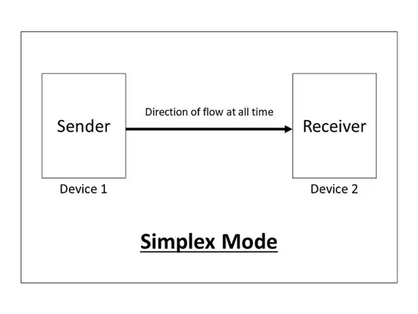
1. Simplex
Simplex is the data transmission mode in which the data can flow only in one direction, i.e., the communication is unidirectional. In this mode, a sender can only send data but can not receive it. Similarly, a receiver can only receive data but can not send it.
This transmission mode is not so popular because we cannot perform two-way communication between the sender and receiver in this mode. It is mainly used in the business field as in sales that do not require any corresponding reply. It is similar to a one-way street.
For Example, Radio and TV transmission, keyboard, mouse, etc.
2. Half-Duplex
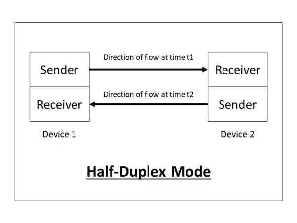
Half-Duplex is the data transmission mode in which the data can flow in both directions but in one direction at a time. It is also referred to as Semi-Duplex. In other words, each station can both transmit and receive the data but not at the same time. When one device is sending the other can only receive and vice-versa.
In this type of transmission mode, the entire capacity of the channel can be utilized for each direction. Transmission lines can carry data in both directions, but the data can be sent only in one direction at a time.
This type of data transmission mode can be used in cases where there is no need for communication in both directions at the same time. It can be used for error detection when the sender does not send or the receiver does not receive the data properly. In such cases, the data needs to be transmitted again by the receiver.
For Example, Walkie-Talkie, Internet Browsers, etc.
3. Full-Duplex
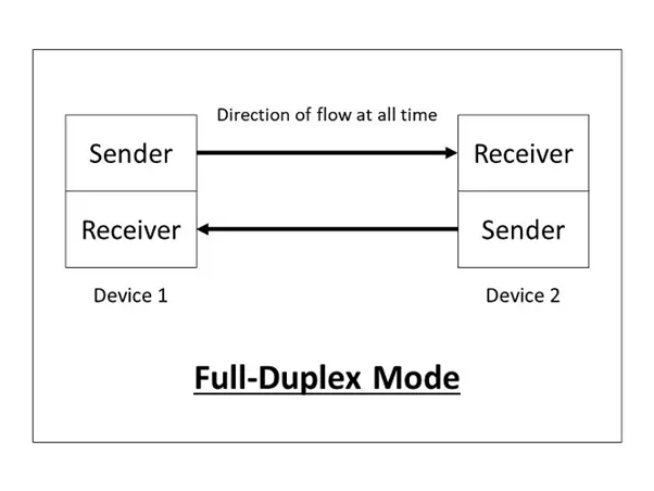
Full-Duplex is the data transmission mode in which the data can flow in both directions at the same time. It is bi-directional in nature. It is two-way communication in which both the stations can transmit and receive the data simultaneously.
Full-Duplex mode has double bandwidth as compared to the half-duplex. The capacity of the channel is divided between the two directions of communication. This mode is used when communication in both directions is required simultaneously.
For Example, a Telephone Network, in which both the persons can talk and listen to each other simultaneously.
According to the synchronization between the transmitter and the receiver:
1. Synchronous
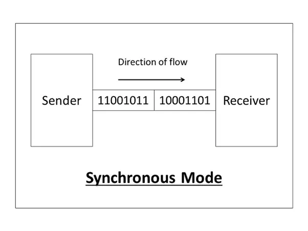
The Synchronous transmission mode is a mode of communication in which the bits are sent one after another without any start/stop bits or gaps between them. Actually, both the sender and receiver are paced by the same system clock. In this way, synchronization is achieved.
In a Synchronous mode of data transmission, bytes are transmitted as blocks in a continuous stream of bits. Since there is no start and stop bits in the message block. It is the responsibility of the receiver to group the bits correctly. The receiver counts the bits as they arrive and groups them into eight bits unit. The receiver continuously receives the information at the same rate that the transmitter has sent it. It also listens to the messages even if no bits are transmitted.
In synchronous mode, the bits are sent successively with no separation between each character, so it becomes necessary to insert some synchronization elements with the message, this is called "Character-Level Synchronization".
For Example, if there are two bytes of data, say(10001101, 11001011) then it will be transmitted in the synchronous mode as follows:
For Example, communication in CPU, RAM, etc.
2. Asynchronous
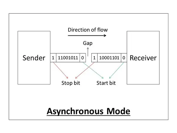
The Asynchronous transmission mode is a mode of communication in which a start and the stop bit is introduced in the message during transmission. The start and stop bits ensure that the data is transmitted correctly from the sender to the receiver.
Generally, the start bit is '0' and the end bit is '1'.Asynchronous here means 'asynchronous at the byte level', but the bits are still synchronized. The time duration between each character is the same and synchronized.
In an asynchronous mode of communication, data bits can be sent at any point in time. The messages are sent at irregular intervals and only one data byte can be sent at a time. This type of transmission mode is best suited for short-distance data transfer.
For Example, if there are two bytes of data, say(10001101, 11001011) then it will be transmitted in the asynchronous mode as follows:
For Example, Data input from a keyboard to the computer.
According to the number of bits sent simultaneously in the network:
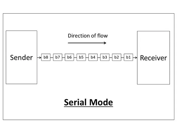
1. Serial
The Serial data transmission mode is a mode in which the data bits are sent serially one after the other at a time over the transmission channel.
It needs a single transmission line for communication. The data bits are received in synchronization with one another. So, there is the challenge of synchronizing the transmitter and receiver.
In serial data transmission, the system takes several clock cycles to transmit the data stream. In this mode, the data integrity is maintained, as it transmits the data bits in a specific order, one after the other.
This type of transmission mode is best suited for long-distance data transfer, or the amount of data being sent is relatively small.
For Example, Data transmission between two computers using serial ports.
2. Parallel
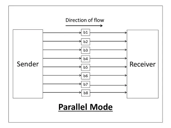
The Parallel data transmission mode is a mode in which the data bits are sent parallelly at a time. In other words, there is a transmission of n-bits at the same time simultaneously.
Multiple transmission lines are used in such modes of transmission. So, multiple data bytes can be transmitted in a single system clock. This mode of transmission is used when a large amount of data has to be sent in a shorter duration of time. It is mostly used for short-distance communication.
For n-bits, we need n-transmission lines. So, the complexity of the network increases but the transmission speed is high. If two or more transmission lines are too close to each other, then there may be a chance of interference in the data, degrading the signal quality.
For Example, Data transmission between computer and printer.
-
Solution:-
2.
 |
Conclusion:-
- BSM is very much important for the Vehicle because it is like the blood which is useful as per our body same like communication is essential.
- using the pseudocode we can write it in different languages
-
Several other factors exist and serve as determinants for choosing between these two platforms and all fall underperformance, capability and budget but the overall selection becomes easier when a proper systems pre-design is in place and the requirements clearly stated. Microcontrollers are mostly used in solutions with a very tight BOM budget and with stringent power requirements while Microprocessors are used in applications with huge computation and performance requirements.
Reference:-
- https://www.tutorialspoint.com/microprocessor/microcontrollers_8051_architecture.htm
- https://circuitdigest.com/article/selecting-between-a-microcontroller-and-microprocessor