MBD Simulation on IC Engine Valve Train
AIM: To study the motion analysis of IC Engine valve train using SOLIDWORKS MOTION.
OBJECTIVES:
- Design all the components
- Assembly all the components
- Perform motion analysis on the assembly
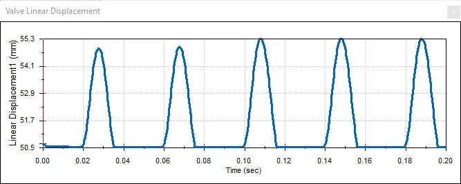
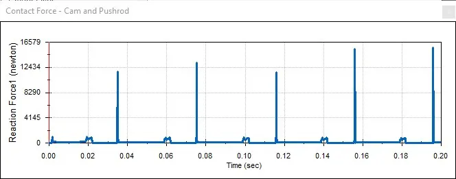
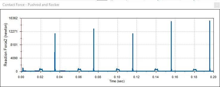
- Obtain plots for Valve Lift & the contact force between Cam and Push Rod, Pushrod and Rocker Arm, Rocker Arm and Valve
- Compare plots and draw a conclusion
THEORY:
Valvetrain
A valvetrain or valve train is a mechanical system that controls the operation of the intake and exhaust valves in an internal combustion engine. The intake valves control the flow of air/fuel mixture (or air alone for direct-injected engines) into the combustion chamber, while the exhaust valves control the flow of spent exhaust gasses out of the combustion chamber once combustion is completed.
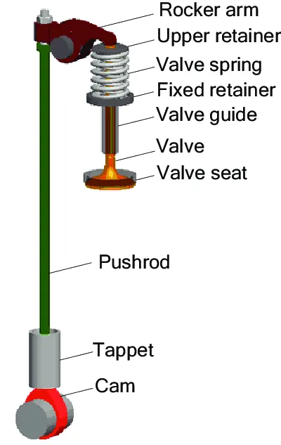
The valvetrain consists of all the components responsible for transferring the rotational movement of the camshaft into the opening and closing of the intake and exhaust valves. Typical components are listed below in order from the crankshaft to the valves.
Camshaft
The timing and lift profile of the valve opening events are controlled by the camshaft, through use of a carefully shaped lobe on a rotating shaft. The camshaft is driven by the crankshaft and— in the case of a four-stroke engine— rotates at half the speed of the crankshaft.
Motion is transferred from the crankshaft to the camshaft most commonly by a rubber timing belt, a metallic timing chain or a set of gears.
Pushrod
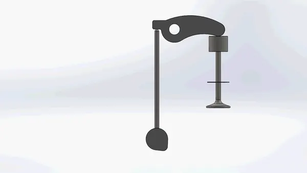
Pushrods are long, slender metal rods that are used in overhead valve engines to transfer motion from the camshaft (located in the engine block) to the valves (located in the cylinder head). The bottom end of a pushrod is fitted with a lifter, upon which the camshaft makes contact. The camshaft lobe moves the lifter upwards, which moves the pushrod. The top end of the lifter pushes on the rocker arm, which opens the valve.
Rocker arm/bucket tappet
Depending on the design used, the valves are actuated by a rocker arm, finger or bucket tappet. Overhead camshaft engines use fingers or bucket tappets, upon which the cam lobes contact. Overhead valve engines use rocker arms, which are actuated by a pushrod and pivot on a shaft or individual ball studs in order to actuate the valves.
Valves
Most modern engines use poppet valves type, although sleeve valves, slide valves and rotary valves have also been used at times. Poppet valves are typically opened by the camshaft lobe or rocker arm, and closed by a coiled spring called a valve spring.
Cam Lift
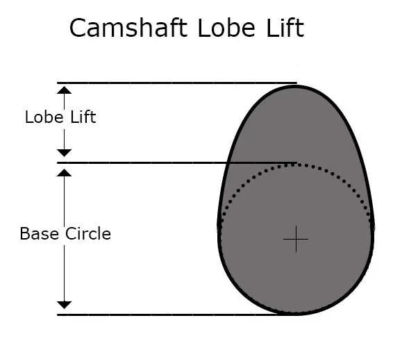
This is the distance the cam lobe rises away from the base circle of the camshaft. It is the distance the lifter will move. It is also called "lobe lift." Some camshaft manufacturers list this value.
GOVERNING EQUATION:
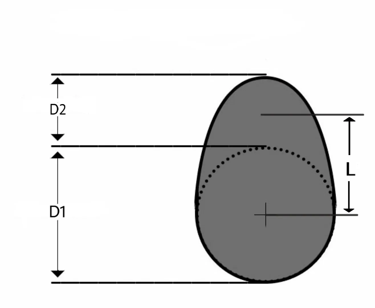
`"Cam lift=(L-D1/2)+D2/2"`
Where,
D1 is the diameter of the bigger circle
D2 is the diameter of the smaller circle
L is the distance between the centre of the two-circle mentioned above
PROCEDURE:
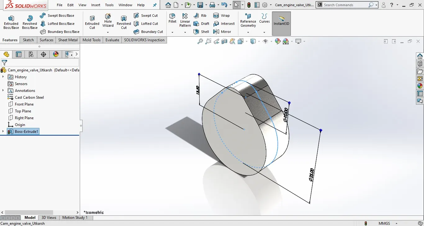
Cam:
Case 1 (Cam lift = 3.5 mm)
Calculation,
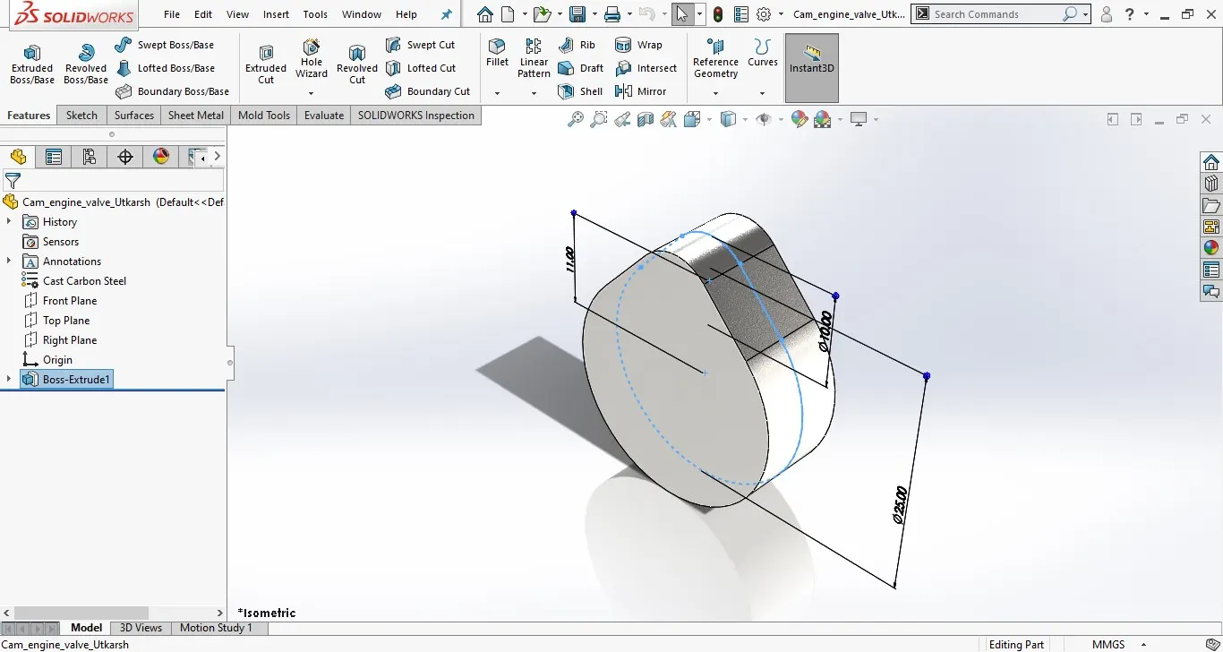
D1 =25 mm, D2 =10 mm, L1 =?
3.5 = (L1-12.5) +5
L1 = 11 mm
Case 2 (Cam lift = 6 mm)
Calculation,
D1 = mm, D2 = mm, L1 =?
6 = (L2-12.5) +5
L2 = 13.5 mm
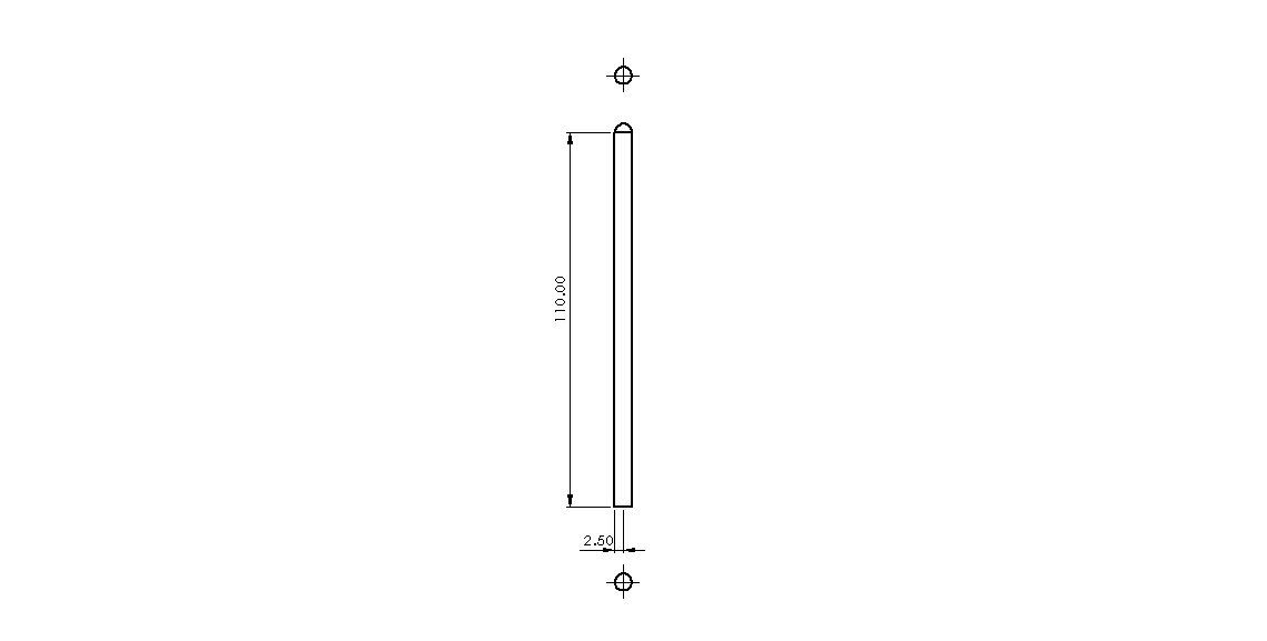
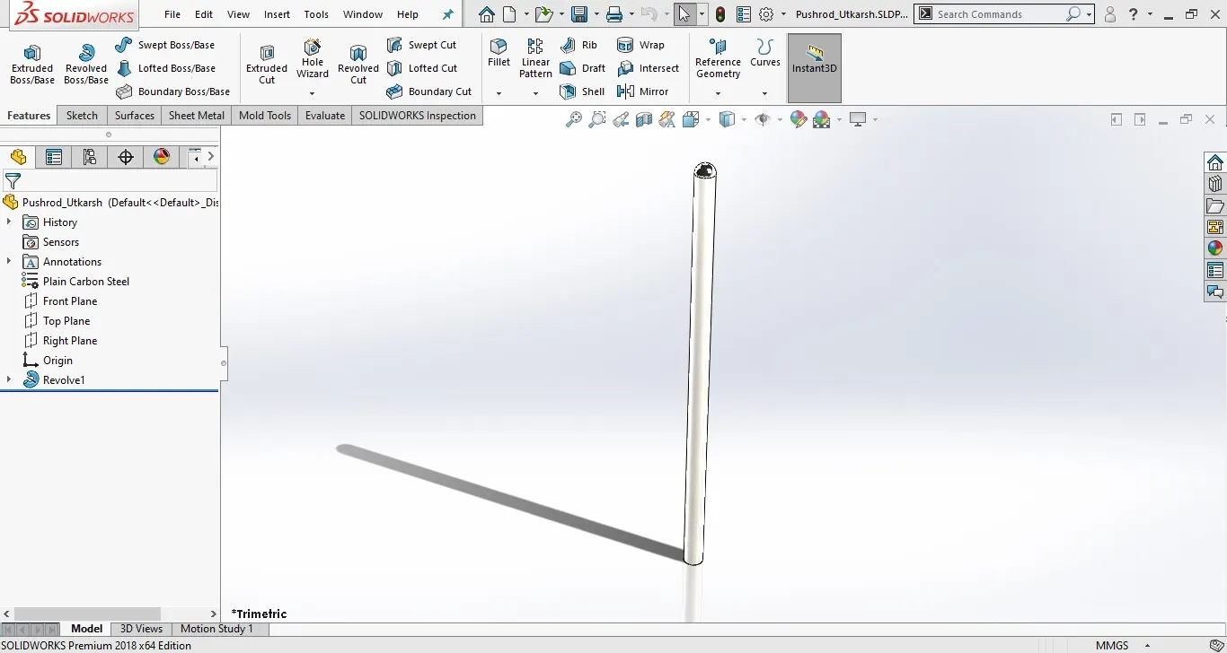
Pushrod:
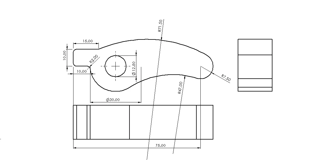
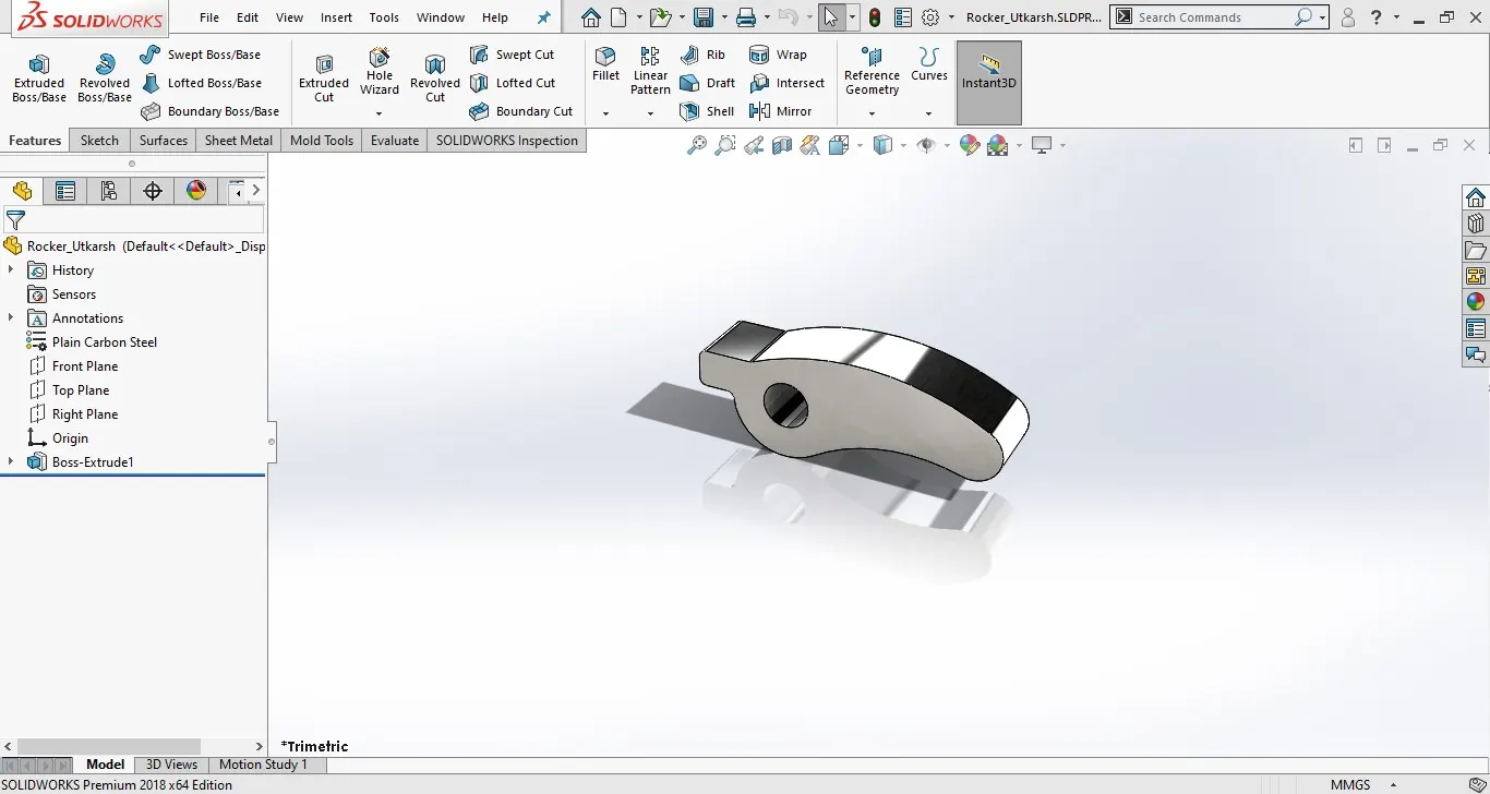
Rocker:
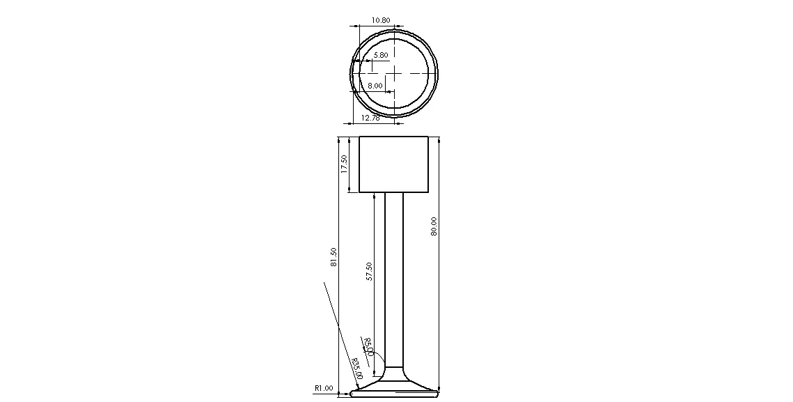
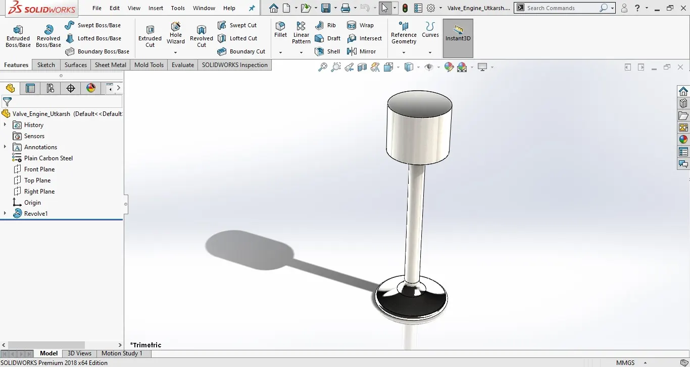
Valve:
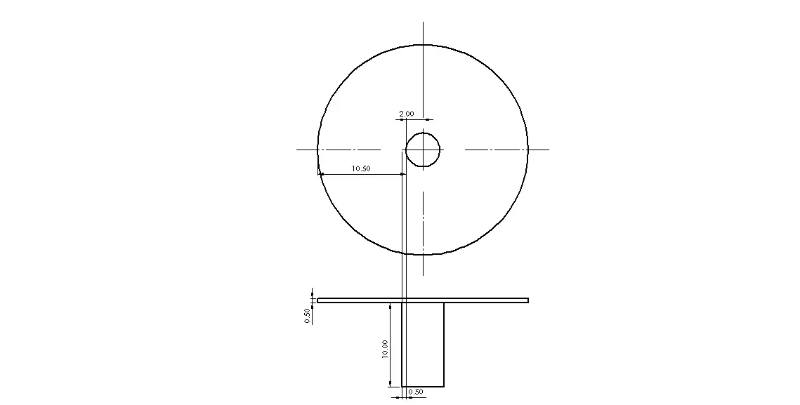
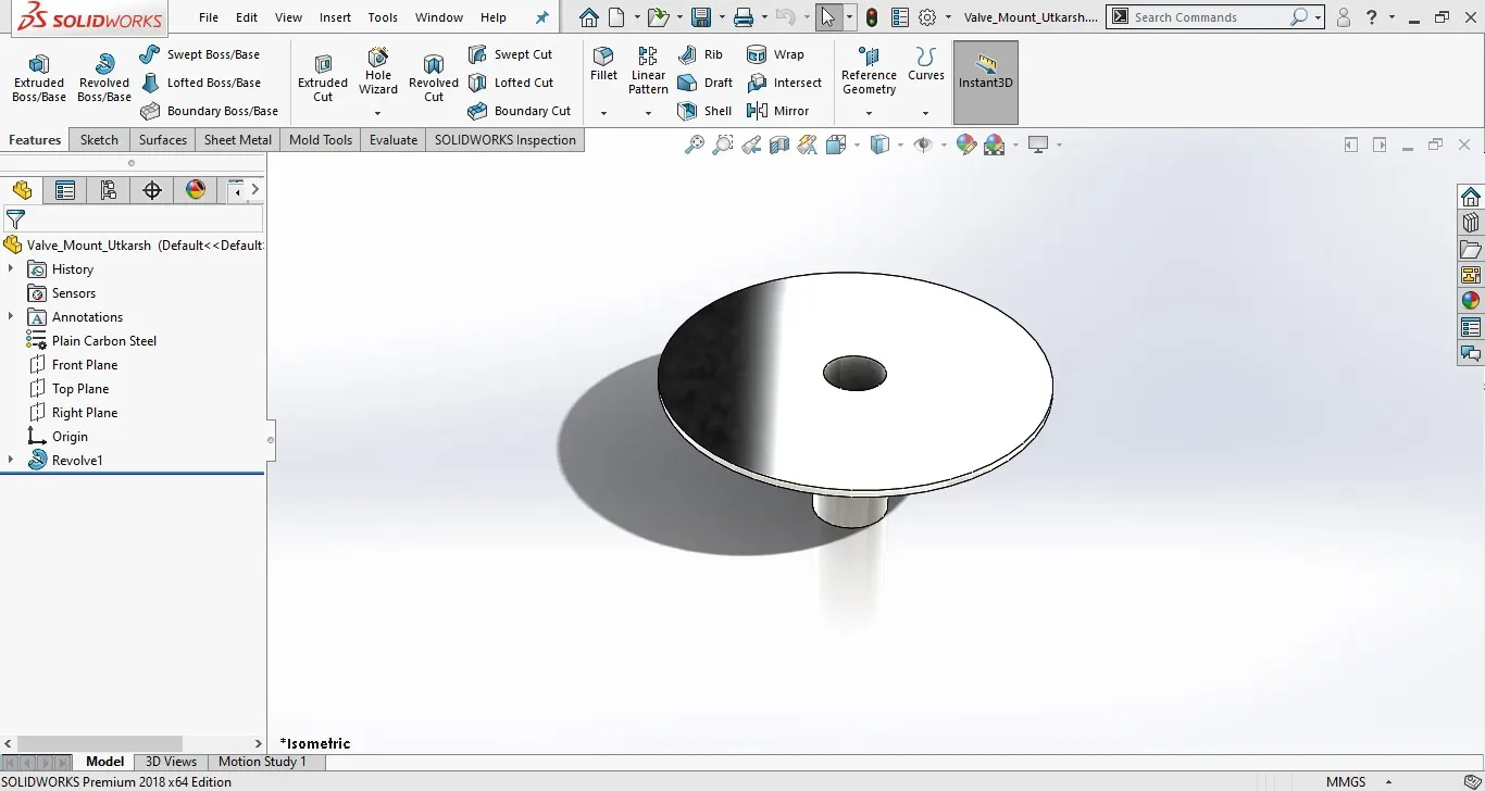
Valve mount:
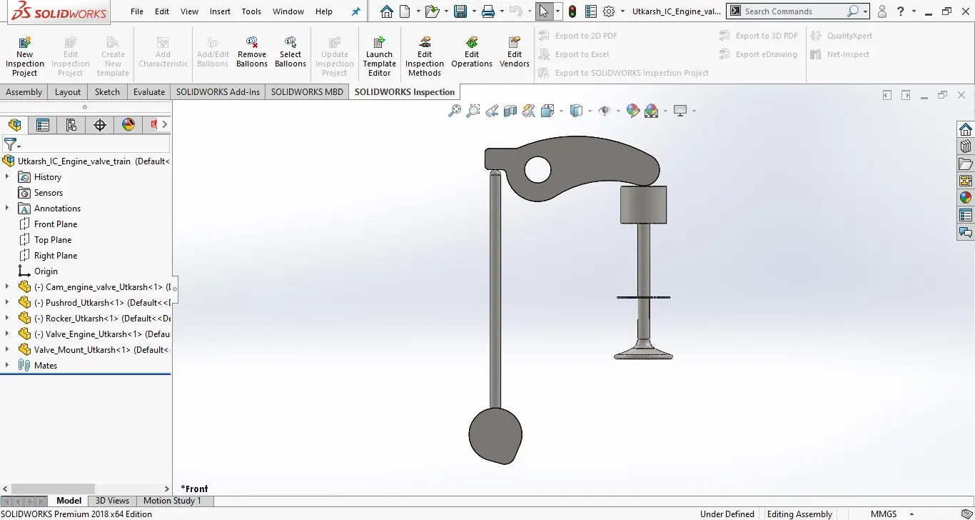
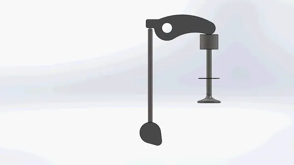
Assembly:
First load all the components of the assembly then provide the following mates:
Rocker hole axis with the assembly right plane
Rocker hole axis with the assembly top plane
Valve mounts front plane with the assembly front plane
Cam front plane with the assembly front plane
Pushrod axis with the assembly front plane
Valve axis with the assembly front plane
Valve mount axis with the assembly front plane
Pushrod axis with the assembly right plane with a distance of 20mm
Cam axis with the assembly right plane with a distance of 20mm
Valve mount axis with the assembly right plane with a distance of 50mm
Valve mount top face with the assembly top plane with 60mm
Valve axis with valve mount axis
Cam axis with the assembly top plane with a distance of 125mm
Rocker front plane with assembly front plane
For Case 1 -
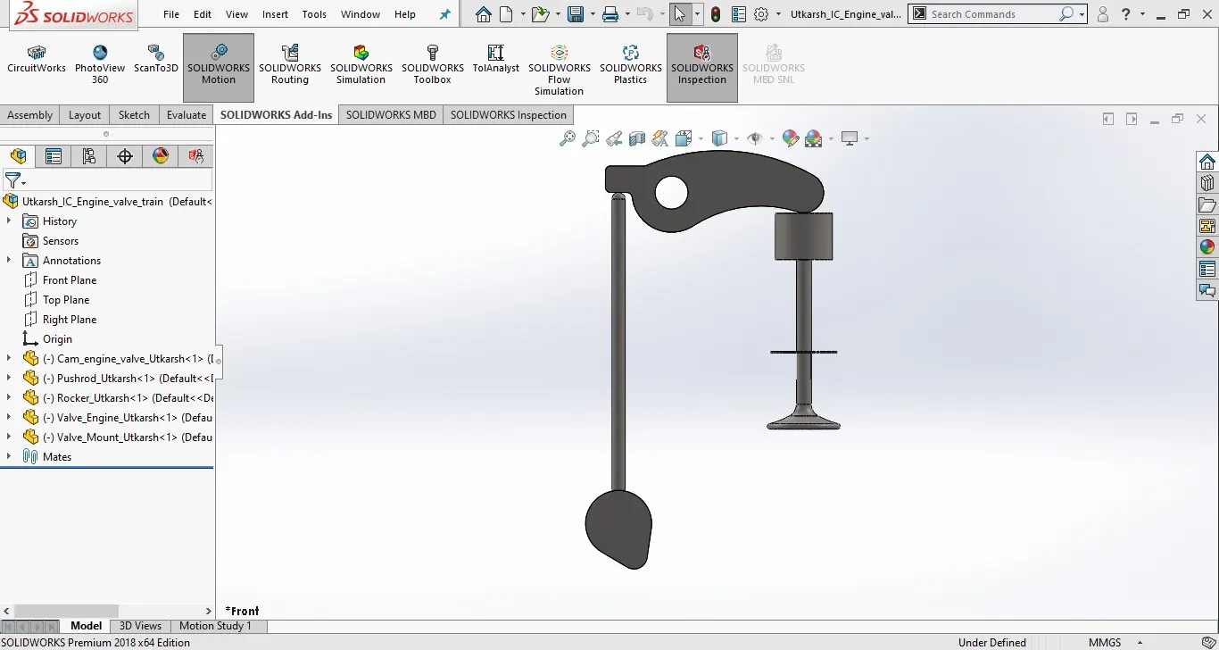
For Case 2 –
Motion Analysis:
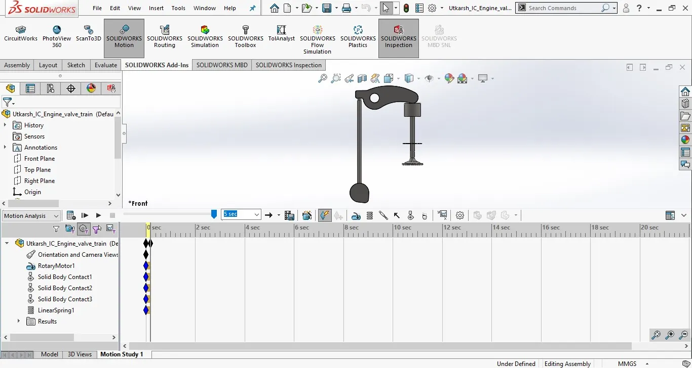
First, enable MOTION ANALYSIS from SOLIDWORKS ADD-INS ribbon then select motion study. From the bottom left corner drop-down options select motion analysis.
In motion study preferences enter the value of 7200 in fps and select use precise contact option.
Insert motor on cam axis with 1500 rpm.
Insert spring by clicking on the spring option. Select the lower face of the valve and upper face of valve mount, give 10mm spring constant and free length of 45mm.
Establish contact between cam and pushrod, pushrod and rocker, rocker and valve.
Select results and plots->displacement/velocity/acceleration->linear displacement->magnitude->top face of valve. For forces between components select results and plots->forces->contact forces-> magnitude->select faces of cam and pushrod, pushrod and rocker arm, rocker arm and valve. For rocker arm plots with respect to X direction select results and plots->forces->contact forces-> X-direction->select rocker arm and valve.
Set analysis time to 0.2 sec as it will take a lot of time.
Select all components (by pressing Ctrl+A), right-click and select edit material properties. From there select Cast Carbon Steel.
Finally, click on calculate button.
RESULT:
Case 1: Cam lift = 3.5 mm
Valve lift
Contact force between cam and pushrod
Contact force between pushrod and rocker arm
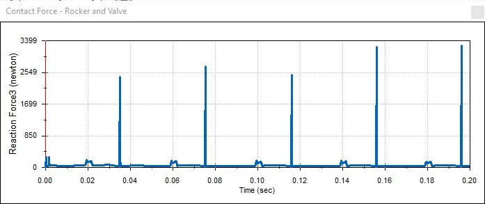
Contact force between Rocker arm and valve with respect to magnitude
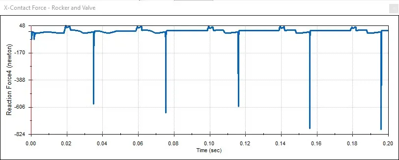
Contact force between Rocker arm and valve with respect to X direction
Case 2: Cam lift = 6 mm
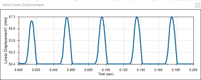
Valve lift
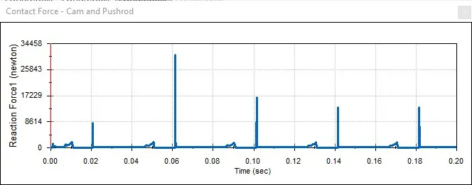
Contact force between cam and pushrod
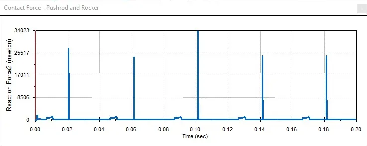
Contact force between pushrod and rocker arm
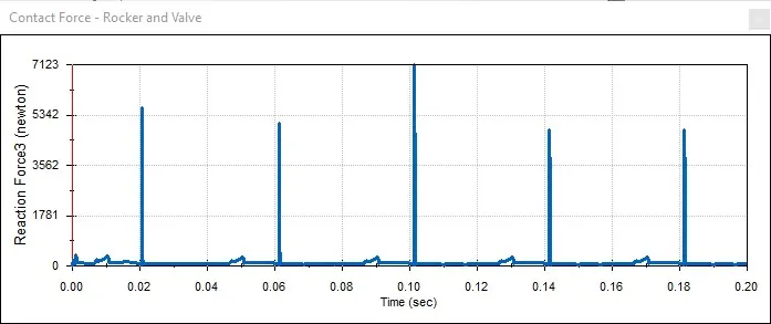
Contact force between Rocker arm and valve with respect to magnitude
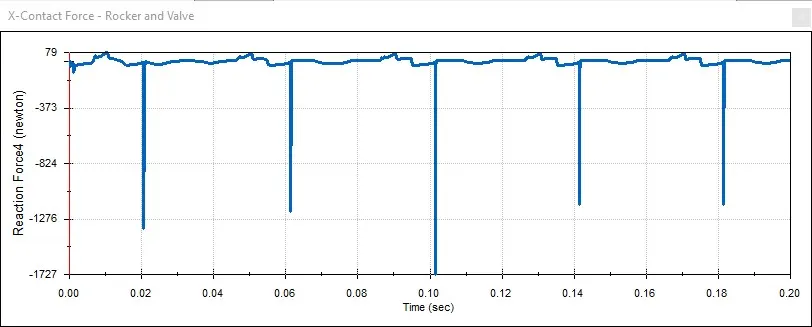
Contact force between Rocker arm and valve with respect to X direction
CONCLUSION:
From the above study, the following points are concluded:
i) On increasing the cam lift, the valve lift also gets increased i.e valve lift is directly proportional to cam lift.
ii) The valve lift is directly dependent on the cam & rocker arm profile. This clearly defines the relation between valve lift and cam-rocker arm profile.
iii) The contact forces between the parts also increases on increasing the cam lift. Since more cam lift stores more potential energy.
iv) The contact force between the rocker arm & valve varies in reference to x-direction & magnitude. Since, the magnitude is the resultant of all the forces acting at a particular point, the plot in reference with magnitude is representing the overall forces acting in between the rocker arm & valve. While the plot in reference with x-direction represents forces acting only in the x-direction. So, it is very less in comparison with magnitude. Moreover, the force acting in the x-direction is only the frictional force.
REFERENCES:
https://www.speedwaymotors.com/the-toolbox/camshaft-specifications-and-terminology/28647
https://help.summitracing.com/app/answers/detail/a_id/4699/~/camshaft-lift
LINKS: