MBD Simulation on IC Engine Valve Train
- AIM -
To carry out a motion analysis of a cam in block IC engine valve train using SOLIDWORKS MOTION.
- OBJECTIVES -
1.Run simulation using below paameters
- cam lif = 3.5mm , cam speed = 1500RPM , material = cast carbon steel
- cam lif = 6 mm , cam speed = 1500RPM , material = cast carbon steel
2. To obtain valve lift
3. To determine contact forces between the following
- Cam and Push rod.
- Push rod and Rocker arm.
- Rocker arm and Valve.
4. Explain why the contact force between thw Rocker arm and valve varies while measuring for the x-direction and measuring for magnitude.
- THEORY -
The cam in block valve train layout of piston engines is one where the camshaft is placed within the cylinder block usally besided and slightly above the crankshaft in a straight engine or directly above the crankshaft in the V of a V engine.This contrasts woth an overhead camshaft design which places the camshafts within the cylinder head and drive valve directly or through short rocker arms.
The valvetrain consists of all the components responsible for transferiing the rotational movement of the cam shaft into the opening and closing of the intake and exhaust valves. Typical components are listed below in order from the crankshaft to valves.
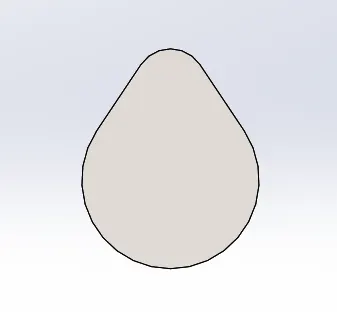
- CAM
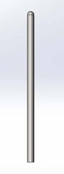
2. PUSH ROD
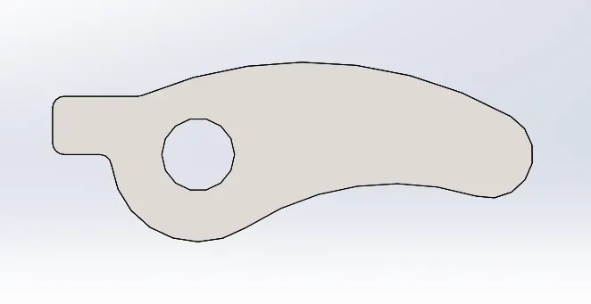
3. ROCKER ARM
4. VALVE
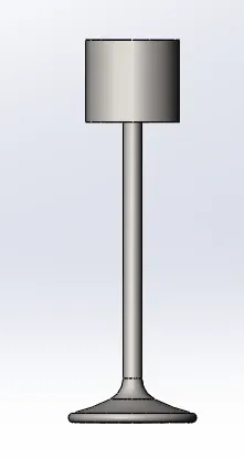
5. VALVE STEM
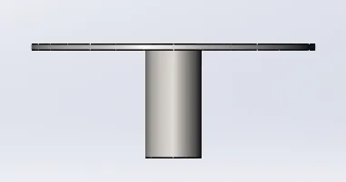
ASSEMBLY
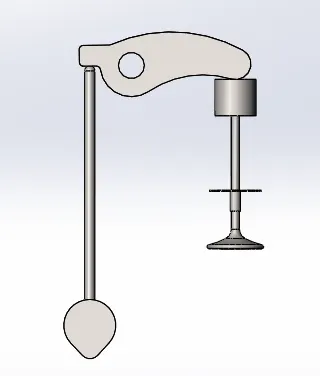
MBD Simulation setup for the two different cam lift conditions:
For the motion analysis study the following to be applied
- Rotating motor is applied to the cam with 1500RPM and direction of rotation.
- All contacts are defined between the components of IC engine valve train mechanism.
- Simulation is then run and results of valve linear displacement, Contact forces in both the cases.
RESULTS AND PLOTS
CASE - 1 for 3.5mm cam lift
Spring parameters - freelength - 45mm , 10 N/mm
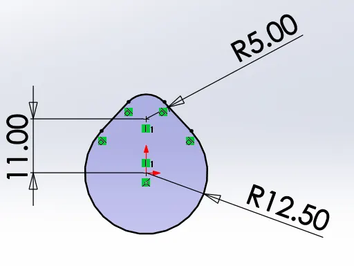
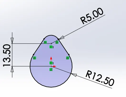
The cam lift is related with the formula
CAM LIFT = (L - R1)+ R2 the model is reflected as same to attain 3.5 mm cam lift.
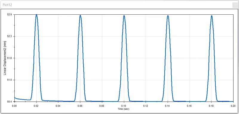
LINEAR DISPLACEMENT OF VALVE (valve lift)
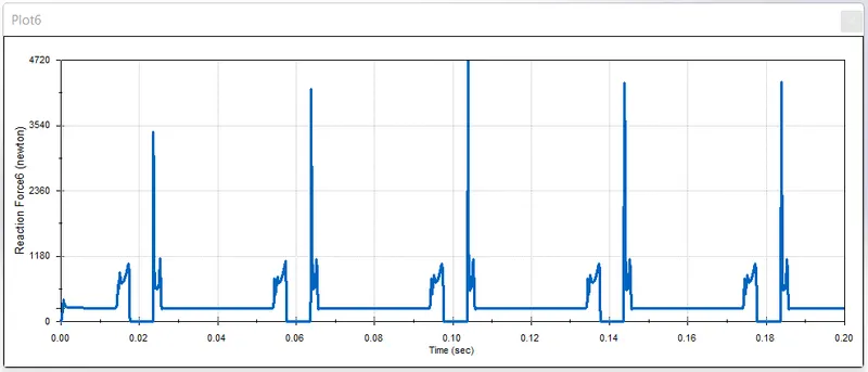
Contact force between cam and pushrod
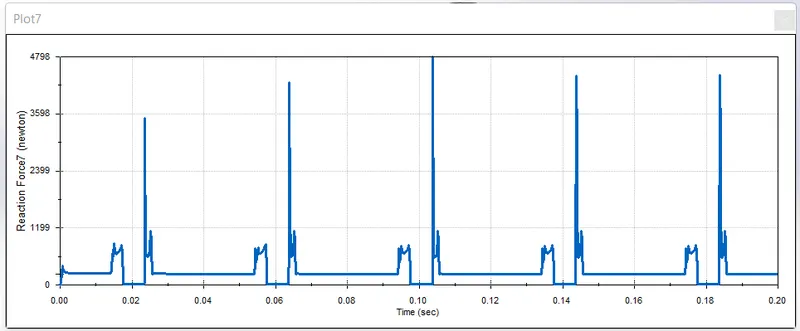
Contact force between pushrod and rocker arm
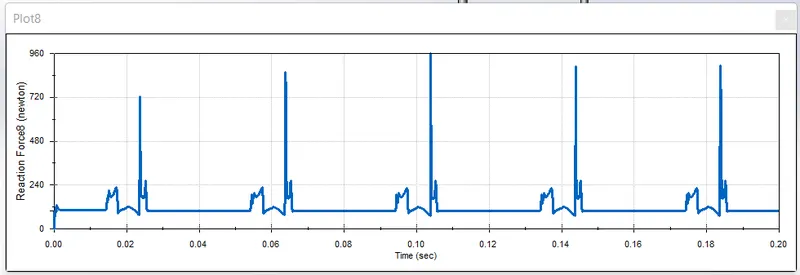
Contact force between rocker arm and Valve
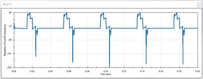
The contact force along x-direction between the valve and rocker arm ranges 56N to -226N. the negative value represents the rocker arm pushing the valve and positive value represents the valve pushing the rocker arm due to spring action.
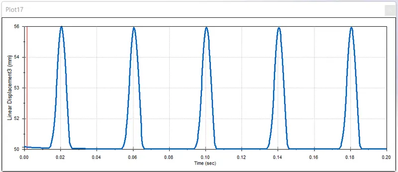
CASE - 2 for 6mm cam lift
LINEAR DISPLACEMENT OF VALVE (valve lift)
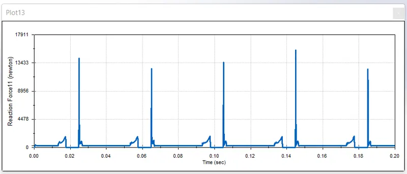
Contact force between cam and pushrod
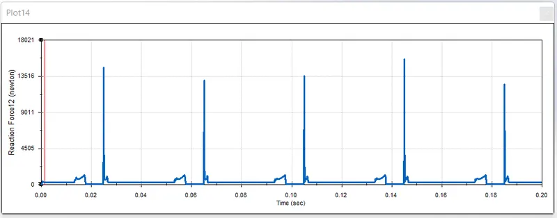
Contact force between pushrod and rocker arm
Contact force between rocker arm and valve
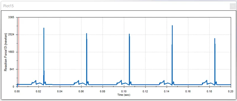
Contact force between rocker arm and valve (X-direction)
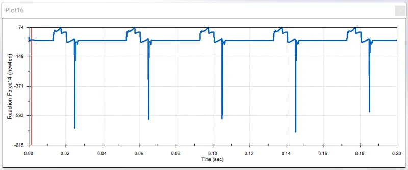
Actually when we study the motion of the rocker arm and the valve we can see that the rocker arm moves in an arc in the x-y plane. The valve moves in linearly along the Y axis The motion of the rocker arm has two components x and y. The magnitude of the rocker arm only pushes the valve downwards but the x-axis gives us only teh friction force between the rocker arm and the valve.Hence,both the values are different.
- Animation links :
CASE-1 : https://youtu.be/y0u3wQfdCpw
CASE-2 : https://youtu.be/KDKU7lX04dw
- OBSERVATIONS :
- The contact forces between all the components follow similar pttern and the forces are maximum at the highest cam lift.
- The valve lift depends on the canm lift and length of rocker arm.While we change the cam lift value in each case the valve lift also increases accordingly.