MBD Simulation on IC Engine Valve Train
AIM:
Analise contact forces and valve lift on engine valve mechanism.
|
S.no |
CAM Lift (mm) |
Speed (RPM) |
Material |
|
1 |
3.5 |
1500 |
Cast Carbon Steel |
|
2 |
6 |
1500 |
Cast Carbon Steel |
EXPLAIN ABOUT THE ENTIRE MOTION STUDY SETUP:
Calculation:
Given R1=12.5 mm, R2=5 mm.
Camlift=(L-R1) +R2
Case 1: if cam lift is 3.5 mm
3.5=(L-12.5) + 5
L= 11 mm
Case 2: if cam lift is 6 mm
6=(L-12.5) + 5
L= 13.5 mm
Design:
These are the five parts required to build our mechanism.
- Cam
- Push Rod
- Rocker Arm
- Valve
- Valve Mount
Cam:
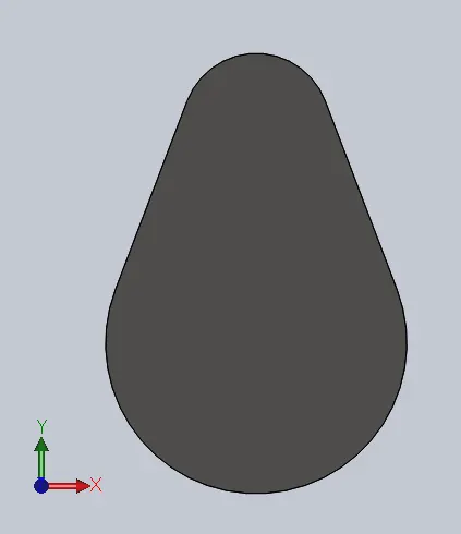
Case 1: draw two circles which are aligned vertically and the center to center distance of 11 mm the upper circle diameter of 10 mm and the lower circle diameter of 25 mm. click ‘L’ and draw two lines joining the circles which acts like tangent and now by the help of power trim we need to remove unwanted curves and extrude the sketch on midplane to a width of 10 mm. Save the part file as cam1.
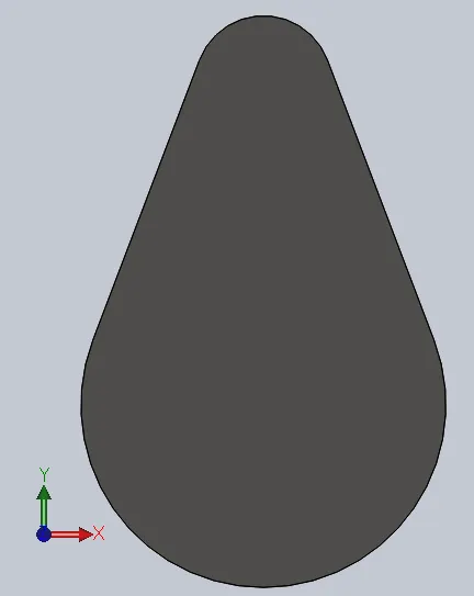
Case 2: draw two circles which are aligned vertically and the center to center distance of 13.5 mm the upper circle diameter of 10 mm and the lower circle diameter of 25 mm. click ‘L’ and draw two lines joining the circles which acts like tangent and now by the help of power trim we need to remove unwanted curves and extrude the sketch on midplane to a width of 10 mm. Save the part file as cam2.
Push Rod:
Select the front plane click on sketch and click “L” and draw a vertical line passing through the origin and a horizontal line of 2.5 mm and a vertical line parallel to the previous one of length 110 mm now draw a 3-point arc between both lines and the center must be aligned on larger line and the radius of 2.5 mm. now by the help of revolve we extrude.

Rocker Arm:
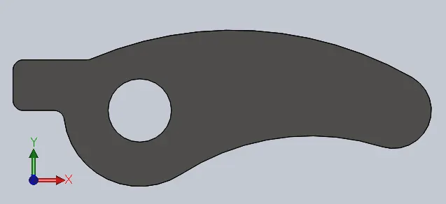
Select the front plane click on sketch and click “L” and draw a horizontal line of length 15 mm and a vertical line passing through the origin of length 10 mm and a horizontal line passing through the origin of length 10 mm now draw two concentric circles in such a way that the center is aligned horizontally to the origin and the outer circle is coincident with the 10 mm horizontal line the diameter of the outer circle is 30 mm and the inner circle diameter is 12.5 mm. now draw two a 3 point curve one above the origin of radius 71.5 mm which is coincident to the outer circle and another bellow origin of radius 47 mm and now draw a 3 point arc of radius 7.5 mm the previous curves are having a tangential mate with the arc the distance from the origin to the center of the arc is 75 mm. Click on the trim to remove unwanted edges and fillet at the curves of radius 2 mm. now extrude the sketch on the midplane to a width of 20 mm.
Valve:
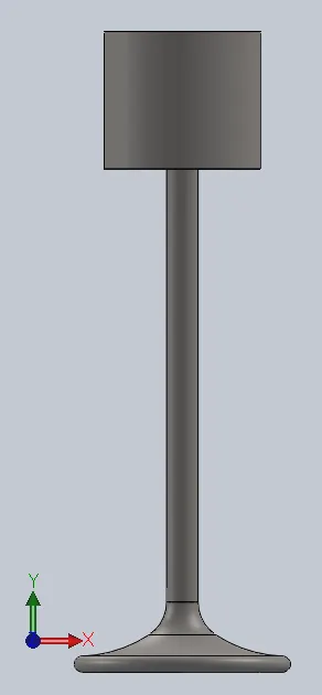
Select the front plane click on sketch and click “L” and draw a vertical line from the origin to a length 80 mm and a horizontal line to left of length 10 mm and a vertical line to downwards of length 17.5 mm and a horizontal line of length 8 mm to right and a vertical line of length 57.5 mm downwards. Now draw two 3-point curves one above the origin of radius 35 mm and another at the left side of the origin of radius 45 mm. now draw a 3-point arc of radius 1 mm joining the curve of 35 mm draw a horizontal line of length 5.8 mm joining 3-point arc and the curve passing through the origin and the distance between the origin to the end of a horizontal line is 12.78 mm. now revolve extrude the valve on the line passing through the origin.
Valve Mount:
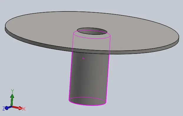
Select the front plane click on sketch and click “L” draw a construction line passing through the origin and draw a vertical line at a distance of 2.02 mm from the origin and a horizontal line to left of length 10.5 mm and a vertical line to downwards of length 0.5 mm and a horizontal line of to right and a vertical line of length 10 mm downwards and horizontal line to the right of length 0.5 mm. now revolve extrude the sketch along the construction line.
ASSEMBLY:
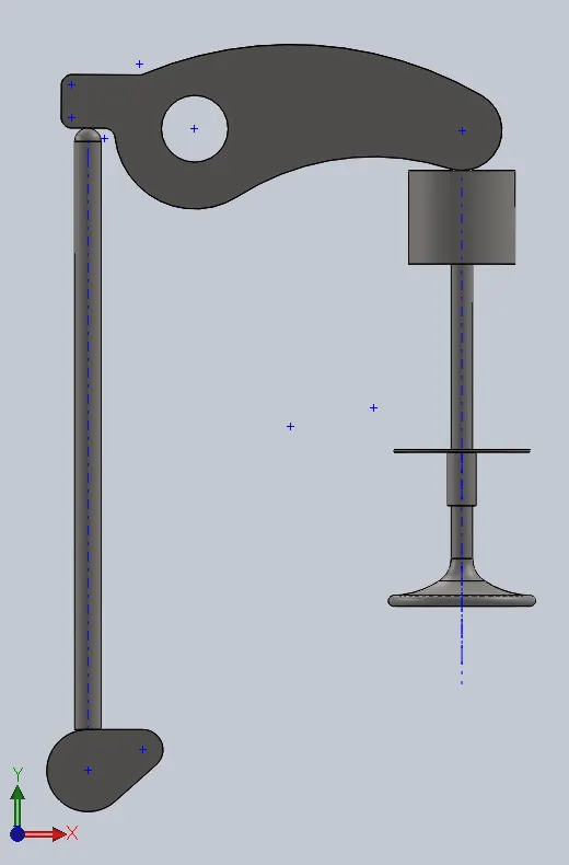
There are two assemblies but there is only one difference between the two Case 1 and case 2 is only in the design of the cam and it is only a cam lift. We import cam 1 in case 1 and cam 2 in case 2 of assembly.
Click on new and select assembly, go to files click on ‘Make assembly from parts’ and select all the parts and import them now right-click on the first part we imported and click on a fix to move the part freely in the space.
Click on mate and select axis of the rocker arm and top plane of assembly for coincident mate, select front plane of the rocker arm and front plane of assembly for coincident mate, select front plane of cam and front plane of assembly for coincident mate, the select axis of the pushrod and front plane of assembly for coincident mate, the select axis of the valve and front plane of assembly for coincident mate, the select axis of valve mount and front plane of assembly for coincident mate, select the axis of the push rod and the right plane of assembly to a distance mate of 20 mm, select the axis of cam and the right plane of assembly to a distance mate of 20 mm, select the axis of valve mount and the right plane of assembly to a distance mate of 50 mm to the right side of the assembly, select the top surface of valve mount and top plane of assembly to a distance mate of 60 mm, select the axis of the valve and valve mount to coincident mate, select the axis of cam and top plane of assembly to distance mate of 120.061 mm.
Assembly 1: Assembly 2:

MULTIBODY ANALYSIS:
The MBD analysis for both case is the same.
Select the axis on the cam and click on the motor to the input of 1500 rpm, select all parts for solid contact and select all the parts and right-click and select material and click on edit material and select cast carbon steel. Click on spring and select linear spring and select the edge of the valve and valve mount to place a spring between them with a load of 10 N/m2 and a free length of 34.7 mm. click on gravity and select ‘Y’ direction. Go to settings and change fps to 7200 and use precise contact. Now to change the simulation duration right-click on the key and select edit-key time and give simulation time to 1 second and click on ok. Now click on calculate to run the analysis.
RESULTS AND EXPLANATION:
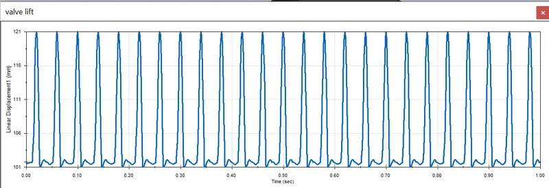
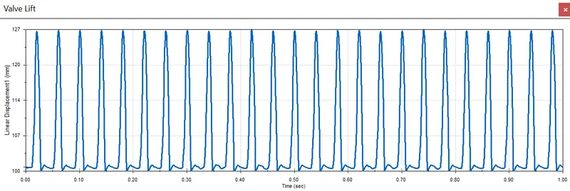
Valve lift:
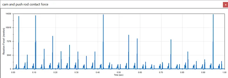
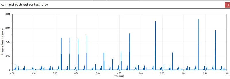
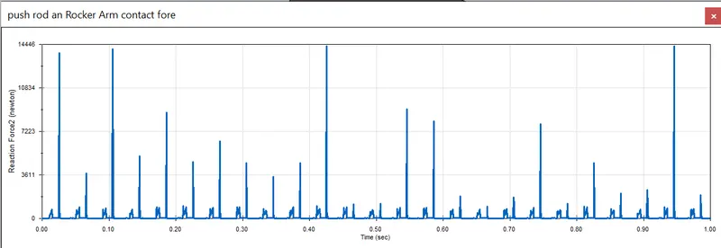
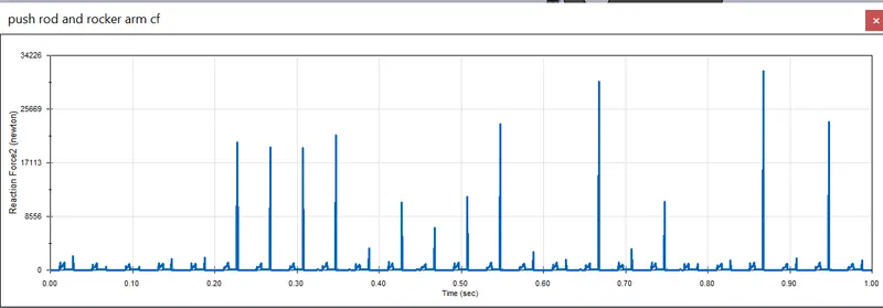
Contact forces between:
- Cam and Pushrod:
case 1:
case 2:
- Pushrod and Rocker arm:
case 1:
case 2:
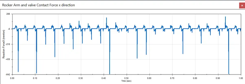
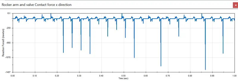
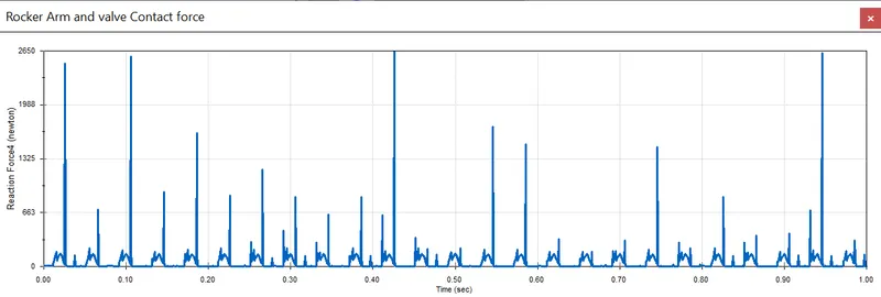
- Rocker arm and valve:
case 1 in x-direction:
case 2 in x-direction:
case 1 Magnitude:
case 2 Magnitude:
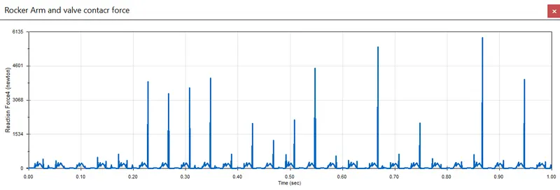
The magnitude of contact force is high than the force in x direction.
The contact force between the Rocker arm and valve varies while measuring with respect to the X direction and measuring with respect to magnitude is because the rocker arm is in osilatery motion over x axis.