MBD Simulation on IC Engine Valve Train
Aim: To model and perform motion analysis on Valve Train
Introduction:
A valvetrain is a component that is designed to open and close the intake and exhaust valves so that air/fuel mixture can enter and leave the combustion chamber as gases.
Nowadays, engines are designed with overhead cam assemblies which are known as an overhead camshaft. It is located near the top of the engine.
Unlike the ones that locate the camshaft lower in the engine and use push rods to move the valve assemblies. This valvetrain layout is called Cam-in-block.
Components of a Valve Train:
a. Valve
b. Rocker Arm
c. Cam
d. Push Rod
e. Stem
Modelling and Assembly
1. Using the given part file, create models of each component and save it seperately.
2. Now import them in an assembly and assign mates to them.
3. Using measure tool, measure distances in rocker arm and piston to assign distance mates properly.
4. Using option 'physical dynamics' in move components, choose the starting position of the motion analysis.
5. Create a motion study and select 'Motion Analysis'.
Motion Analysis
For Motion Analysis, we will consider two cases:
| Sl.No | CAM Lift (mm) | Speed (RPM) | Material |
| 1 | 3.5 | 1500 | Cast Carbon Steel |
| 2 | 6 | 1500 |
Cast Carbon Steel |
For each case, we have to calculate the distance between the centres and accordingly alter the Cam component for each case.
Formula used :
Cam Lift= (L-R1) + R2
Radius of big circle = R1 = 12.5mm
Radius of small circle = R2 = 5mm
Calculations:
CASE I:
Cam Lift= (L-R1) + R2
3.5= L-12.5+5
L=11mm
CASE II:
Cam Lift= (L-R1) + R2
6= L-12.5+5
L=13.5mm
Motion Study:
1. Add a motor to axis of the cam with speed 1500 rpm
2. Add solid contacts between the components
3. Add a spring between Valve and Stem with values 10N/mm and length= 45mm. The spring should be compressed.
4. Now change frame rate settings to 9000 fps and enable precise contact.
5. Start motion calculation and get the outputs.
Outputs:
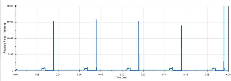
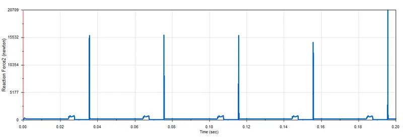
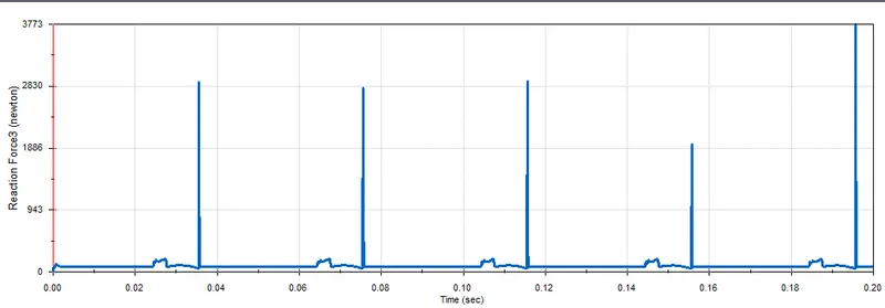
CASE I:
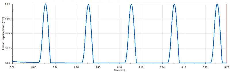
Cam Lift = 3.5 mm
Valve Lift (Linear Displacement) vs Time
Contact Force between Cam and Push Rod vs Time
Contact Force between Push Rod and Rocker Arm vs Time
Contact Force between Valve and Rocker Arm vs Time
CASE II:
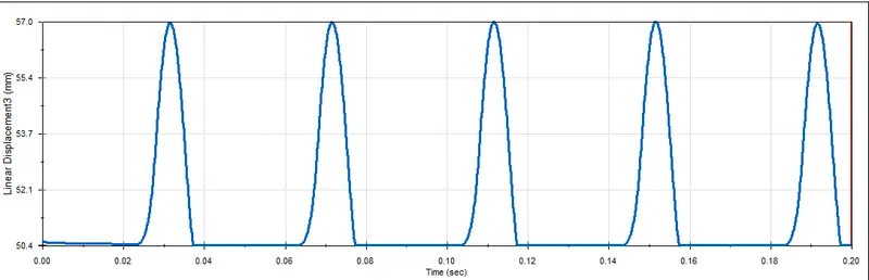
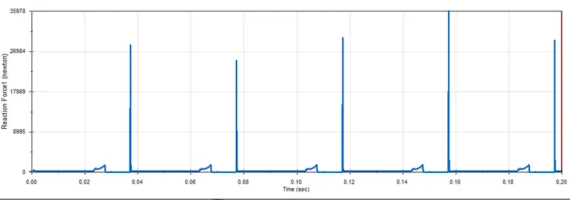
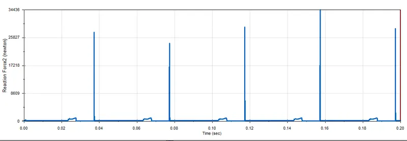
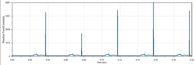
Cam Lift= 6mm
Valve Lift (Linear Displacement) vs Time
Contact Force between Cam and Push Rod vs Time
Contact Force between Push Rod and Rocker Arm vs Time
Contact Force between Valve and Rocker Arm vs Time
Observation and Results:
1. There is a difference between the graphs of contact force between the Rocker arm and valve with respect to the X direction and magnitude.
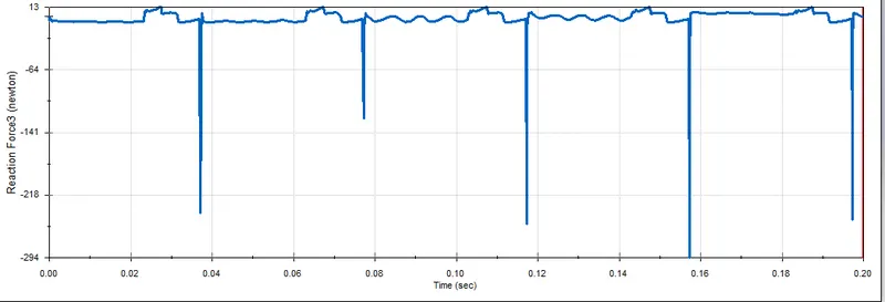
This is because, along the X direction, the force measured is the frictional force when the rocker arm slides over the valve. Whereas, magnitude measures the total contact force from the spring as well as the frictional force. The direction is reversed because it takes the sum of when the rocker arm slides and then slides back over.
2. By increasing the Cam lift, the contact forces and valve lift increase and more air-fuel mixture can enter the IC Engine cylinder.
Drive Link:
https://drive.google.com/drive/folders/1abXBSkRQBo72R06mFuAMP3wmZ1AGogw8?usp=sharing