MBD Simulation on IC Engine Valve Train
Aim :- MBD Simulation on IC Engine Valve Train using Solidworks.
Objective :- To create a 3D model of IC engine valve train using solidworks of cam lift 3.5mm and 6mm respectively. Plot the graph of linear displacement of the valve and contact force between the components in each of the two cases.
Software :- Solidworks 2019
Theory :- A valvetrain or valve train is a mechanical system that controls operation of the intake and exhaust valves in an internal combustion engine.The intake valves control the flow of air/fuel mixture (or air alone for direct-injected engines) into the combustion chamber, while the exhaust valves control the flow of spent exhaust gasses out of the combusion chamber once combustion is completed.
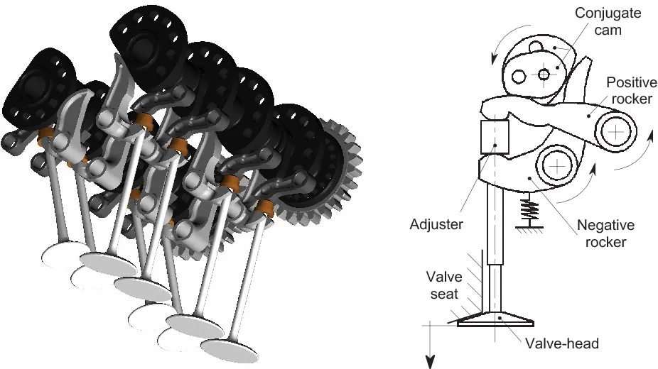
Components :-
1.Cam :-A cam is a rotating or sliding piece in a mechanical linkage used especially in transforming rotary motion into linear motion
2. Push Rod:-A metal rod transmitting the reciprocating motion that operates the valves of an internal-combustion engine having the camshaft in the crankcase.
3.Rocker Arm:- A rocker arm is an oscillating lever that conveys radial movement from the cam lobe into linear movement at the poppet valve to open it.
4.Valve:- Valves are mechanical components used in internal combustion engines to allow or restrict the flow of fluid or gas to and from the combustion chambers or cylinders during engine operation.
5.Valve Stem:- A valve stem is provided to guide the valve in the proper direction
Assembly :- Now assemble the created components of engine valve train as shown in the figure.
There are two case in the given assembly
Formula to calculate cam lift :https://drive.google.com/file/d/1HYeX2n6wKf_phWrOLGxUlQeJPmaaww9x/view?usp=sharing
Case 1 : Where Cam lift is 3.5mm
Calculate the distance between the two circles in cam by using the formula given above.
Case 2 : Where Cam lift is 6mm
Calculate the distance between the two circles in cam by using the formula given above.
Now, Place a motor of 1500 RPM cam in the both cases. Place a distance of 125mm from the top plane of the assembly to the axis of the cam.
Plots :-
1.Case 1 :- Cam lift :3.5mm
1.Linear Displacement of the valve
2. Contact Force between cam & push rod
3. Contact force between Push rod and rocker arm
4. Contact Force between rocker arm and valve
2.Case 2 :- Cam lift :6mm
1.Linear Displacement of the valve
2. Contact Force between cam & push rod
3. Contact force between Push rod and rocker arm
4.Contact Force between rocker arm and valve
Comparision :- Compairing the contact force between rocker arm and valve in magnitude and towards X direction.
Contact force between rocker arm and valve in magnitude:
Contact force between rocker arm and valve towards X direction:
Explaination :- Contact force between the rocker arm and valve in magnitude gives the net contact force through all the direction. In addition the contact force between rocker arm and valve with respect to X direction gives the contact force only through the X direction. As th valve is moving upward and downward direction through the x axis we can observe positive and negative values in the graph and not in the graph of magnitude.
Result :- The following is the youtube link given below which is the simulation of the IC Engine Valve Train .
The following is the Google Drive link of the assembly files
https://drive.google.com/drive/folders/1d1z3nxllGKMYKBKWQQhIN9dpk1ueVEim?usp=sharing