MBD Simulation on a Piston Assembly
AIM:
To perform motion analysis on piston assembly. The motion analysis is going to be carried out in three different conditions,
|
S.no |
Wrist Pin Offset ` |
Crank Speed (Rpm) |
|
1 |
"0" mm |
2000 |
|
2 |
10 mm Positive |
2000 |
|
3 |
10 mm Negative |
2000 |
EXPLAIN ABOUT THE ENTIRE MOTION STUDY SETUP:
DESIGN:
We have to design a total of 5 components in this piston assembly and they are
- Piston
- Connecting rod
- Endcap
- Wrist pin
- Crank
Piston:
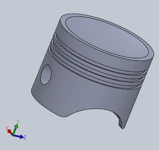
It is a cylindrical component with rings and holes on it. Open a new part file and select the front plane Go to sketch and click on the line command to draw some lines from the origin and a three-point arc according to the given dimensions and then use revolve command to extrude the cylinder and now click on the front plane and draw a rectangle of length 2.5 mm and height 5 mm and it is placed at 5 mm above the origin at the right side of the piston and create a vertical construction line passing through the origin. And now click on revolve cut now we had made a ring on the cylinder then click on the linear pattern in features and select top plane and the distance between the rings is 10 mm and the number rings is 3. click on the front plane and draw a circle of diameter 25.4 mm which is placed vertically to the origin at a distance of 40 mm and go to features and click on extrude cut and select midplane or through all both sides check for the direction to cut and click ok. Now select the right plane and click on sketch draw a three-point arc with a radius of 45 mm and center to the arc length of 42 mm and go to features and click on extrude cut select through all both sides and check for direction of cut and click ok and apply 10 mm fillet to all four corners.
Connecting Rod:
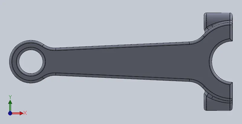
Select the front plane to click on sketch and draw two concentric circles the inner circle is of diameter 25.4 mm and the outer circle is at an offset distance of 10 mm and draw another two concentric circles at a distance of 212.5 mm, the inner circle is of diameter 43.75 mm and the outer circle is at an offset distance of 20 mm the centers of both the circles are aligned horizontally with respect to the origin. Draw a construction line passing through both the centers. Now click ‘L’ and draw a line joining both outer circles the distance between the smaller circle and the line is 14.1 mm and the distance between the larger circle and the line is 21.45 mm, apply a fillet of 20 mm on the corners and by the help of mirror command mirror the line with respect to constriction line. Now click ’L’ and draw a line in the bigger concentric circle joining the outer circle and now use trim command select power trim and remove unnecessary lines and extrude over midplane of length 30 mm. Now click on the face of the bigger concentric circle and draw a circle at the edge of diameter 20 mm and aligned vertically with origin extrude it of length 30 mm and mirror it with respect to the top plane. Now click on sketch on the same face and draw a circle of diameter 11.25 mm at the same center as the previous circle and extrude cut it to a length of 30 mm and mirror it over the top plane. And now apply a fillet of 2.7 mm on all the edges.
End Cup:
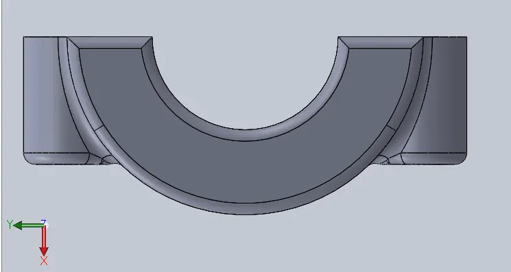
Select the front plane click on sketch and draw two concentric circles the inner circle is of diameter 43.75 mm and the outer circle is at an offset distance of 20 mm click ‘L’ and draw a line joining the inner and outer circle at the center and click on trim and select power trim and remove the other half of the circle and click on extrude over midplane of length 30 mm. Now click on the face of the bigger concentric circle and draw a circle at the edge of diameter 20.5 mm and aligned vertically with origin extrude it of length 30 mm and mirror it with respect to the top plane. Now click on sketch on the same face and draw a circle of diameter 11.25 mm at the same center as the previous circle and extrude cut it to a length of 30 mm and mirror it over the top plane. And now apply a fillet of 2.7 mm on all the edges.
Wrist Pin:
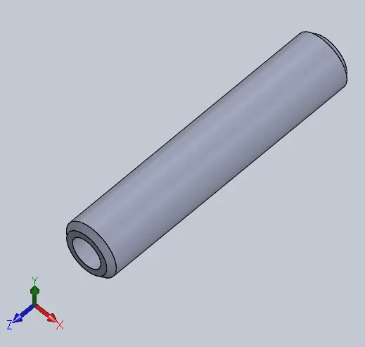
It is a hollow cylinder with a length of 127 mm and an outer circle diameter of 25.5 mm and the inner circle is an offset distance of 5.5 mm. go to fillet click on the chamfer of length 2.5 mm and 45o.
Crank:
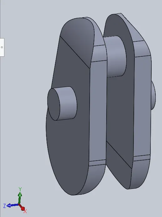
Select the front plane click on sketch and draw two three-point curves the smaller one above the origin and the bigger one below. The smaller curve is placed at a distance of 45 mm and has aligned vertically with the origin and click ‘L’ and draw a line joining small and big curves of length 120 mm. The dimensions of the smaller curve of radius 50 mm and the distance between two endpoints of the curve which are aliened horizontal to each other are 80 mm and the dimensions of the bigger curve of radius 60 mm and the distance between two endpoints of the curve which are aliened horizontal to each other are 120 mm and apply a fillet of radius 25mm on the edges then extrude the sketch for the length of 20 mm. Now click on the face and draw a circle of diameter 43.75 mm and place the circle above the origin aligned vertically at a distance of 50 mm and extrude it to the length of 16 mm. Now click on the opposite face of the crank and draw a circle of diameter 35 mm as its center as the origin and extrude it to the length of 20 mm. Select the right plane click on sketch and draw a three-point curve at top of the crank with given dimensions and extrude cut the sketch through all on both sides and then repeat this process for the bottom side. Now we use the mirror command to over the surface of the circle extrusion of diameter 43.75 mm and mirror the entire half crank.
ASSEMBLY:
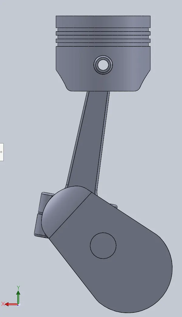
First, we import the crank and remove its restriction and we use coincident mate for the crank axis to the top and right plane of the assembly. Now we use distance mate for the front plane of the crank to the front plane of the assembly.
Second, we import connecting rod and end cup, click on the axis’s of both 30 mm extrude holes to coincident mate, and select both trimmed surfaces to coincident mate. Now select the axis of the crank and axis of connecting rod to coincident mate and a distance mate of 1mm between the surfaces of connecting rod and crank.
Third, we import piston and wrist pin perform coincident mates one by selecting both their respective axis and two for their respective front plane. Now select the front plane of connecting rod and piston to coincident mate.
Forth, perform a coincident mate between the piston right plane and assembly right plane to restrict the rotary motion to only vertical linear motion.
“THIS FOURTH STEP IS TRUE FOR CASE 1 BUT IT WILL BE SLIGHTLY DIFFERENT FOR OTHER CASES.”
MOTION STUDY:
Go to solid works add-ins and click on solidworks motion study and click on motion study 1 and select motion study. Now click on the motor and select the crank axis and give 2000 rpm as input, click on contacts and select solid contact between all the five parts and give dry steel as their material and set the gravity to ‘y’ direction. Go to motion analysis settings and give 2000 fps and precision contact as final inputs.
RESULTS AND EXPLANATION:
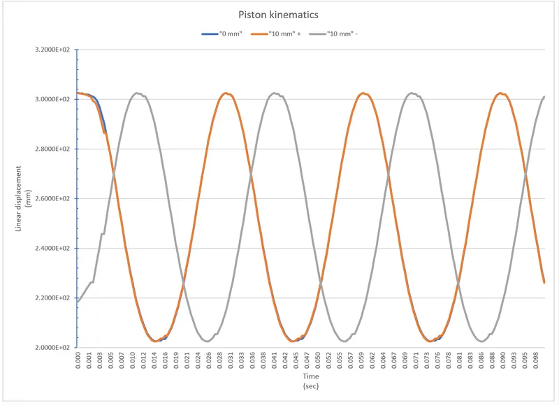
"0 mm" "10 mm" positive "10 mm" negtive
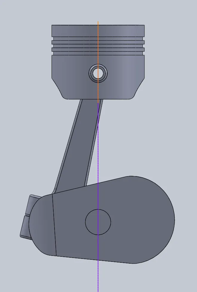
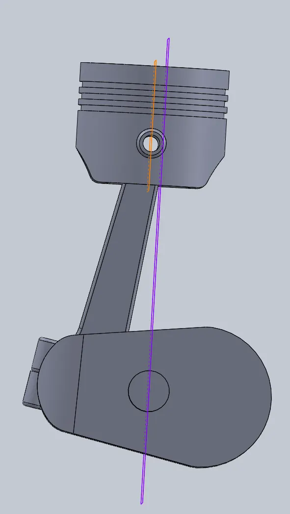
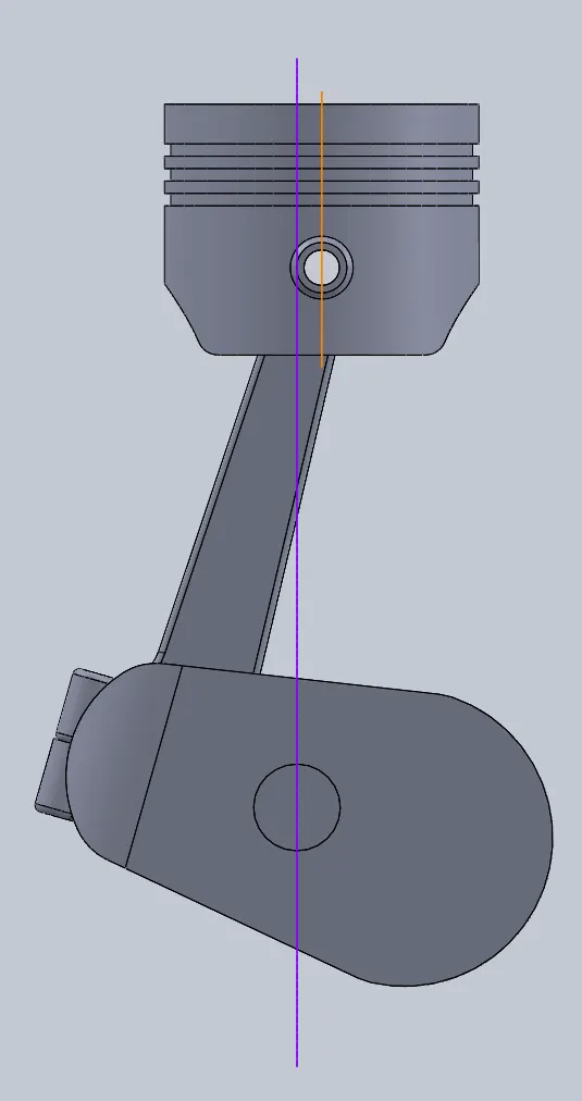
Case 1: "0" mm with 2000 rpm.
This is a case when both the piston axis and crank axis are aligned.
Case 2: 10 mm Positive with 2000 rpm.
This is a case when both the piston axis and crank axis are offset by 10 mm to the left side.
Case 3: 10 mm Negative with 2000 rpm.
This is a case when both piston axis and crank axis are offset by 10 mm to the right side.
the linear displacement in all the 3 cases is the same because the piston has traveled 7 from top dead center to bottom dead center in 1 sec in all the cases