MATLAB program for plotting PV diagram of otto cycle one of the air standard cycles.
AIM :
Write a MATLAB program for plotting PV diagram of otto cycle one of the air standard cycles.
THEORY:
Air Standard Cycle: The cycle in which air is used as a working substance is called an air standard cycle.
Otto cycle is an air-standard cycle that approximates the processes in petrol or diesel engines. It is based on constant volume heat addition (combustion) and heat rejection processes, and isentropic compression and expansion. It is named after Nikolaus A. Otto, who built a successful four-stroke engine in 1876 in Germany using a cycle proposed by Frenchman Beau de Rochas in 1862.
Adiabatic process: An adiabatic process is one in which no external heat enters or leaves the system under consideration.
Isentropic process: an isentropic process is an idealized thermodynamic process that is both adiabatic and reversible. The work transfers of the system are frictionless, and there is no transfer of heat or matter.entropy is constant during the process.
PROCESS OF OTTO CYCLE:
Otto cycle consists of 4 different process
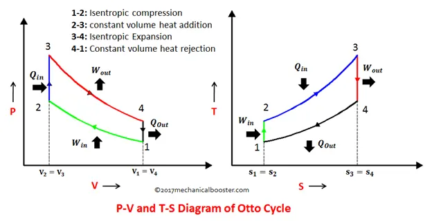
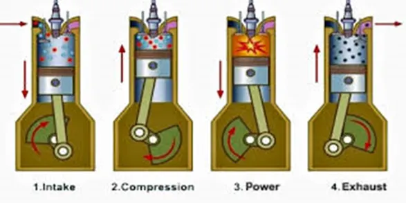
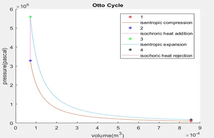
- Process 1–2 is an adiabatic (isentropic) compression of the charge as the piston moves from the bottom dead center (BDC) to top dead center (TDC).
- Process 2–3 is a constant-volume (isochoric )heat transfer to the working gas from an external source while the piston is at top dead center. This process is intended to represent the ignition of the fuel-air mixture and the subsequent rapid burning. the piston moves from the top dead center (TDC) to the bottom dead center (BDC) .
- Process 3–4 is an adiabatic (isentropic) expansion (power stroke). the piston moves from the bottom dead center (BDC) to the top dead center (TDC) .
- Process 4–1 completes the cycle by a constant-volume (isochoric )process in which heat is rejected from the system, while the piston is at the bottom dead center the piston moves from the top dead center (TDC) to the bottom dead center (BDC).
TERMS USED :
TDC - top dead center
BDC - bottom dead center
Stroke - distance between TDC and BDC
Vc - combustion chamber volume(m^3)
Vs - swept volume(m^3)
Vt - total volume cylinder(m^3)
d - bore diameter of the cylinder
l - stroke of the cylinder
P = Pressure (N/m^2)
V = Volume (m^3)
T = Temperature (Kelvin)
γ = ratio of specific heats for the fluid.
R = Ratio of length of connecting rod to crankpin radius
(A)crank pin radius = stroke length/2
FORMULA :
Total volume cylinder:
It refers to the total volume of the cylinder in which (otto cycle) takes place,
Total cylinder volume = Vc + Vs
Where, Vc - Clearance Volume
Vs - Swept volume.
Volume swept:
v=(3.14)/4*d^2*l
Stroke volume:
Stroke volume is the difference between a total cylinder volume and the clearance volume.
vs = total cylinder volume-clearance volume
Clearance volume :
The clearance volume is a volume between the cylinder head and the piston top when the piston is at the top dead center (TDC). It can also be defined as the volume of a cylinder that is not swept by the piston.
v_c = v_s/(cr-1)
Compression ratio:
A compression ratio is defined as the sum of the volume clearance and the volume swept by the volume clearance. It expressed by the equational form as,
Cr = V swept+V clearance/ V clearance
Adiabatic process
PV^γ=Constant
where,
P = Pressure of the system;
V = Volume of the system;
γ = gamma, the ratio of specific heats for the fluid.
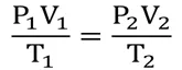
Combined gas law – This law is stated as the volume of a given amount of gas is proportional to the ratio of its temperature and pressure.
Thermal efficiency:
EQUATION TO TRACE VOLUME:

CODE EXPLANATION:
- Firstly, we define inputs like bore, stroke, connecting rod, compression ratio, gamma, and temp and pressure at state point 1 and temperature at state point 3.
- By using governing equation and ideal gas equation we can find the other value of pressure, temp, and volume at different state points.
- But, in this way, we get only four values of pressure and volume which isn't enough and we get a straight line instead of curves at both adiabatic compression and expansion.
- Therefore We have to use a different formula that plots all the points as crank angle changes.
- We define a function[v] called engine kinematics where wer have defined a funvction to calculate clearance volume swept volume and actual volume at different crank angle .
- In the main code, we call this function and find the different values of volume at different angles for compression and expansion.
- we get accurate values of pressure, temp, and volume at different state points from 1 to 4.
OUTPUT GRAPH:
EFFICIENCY:
RESULT AND CONCLUSION:
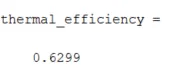
- The thermal efficiency(air standard efficiency ) was found to be 62.99%.
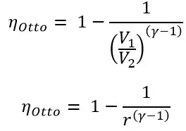
- Hence, air standard efficiency depends only on the compression ratio.
- Therefore for a high compression ratio, air standard efficiency is high.
Main program
clear all
close all
clc

%input
gamma = 1.4
t3 = 2300              %in Kelvin


%state variables
p1 = 101325           %in Pa
t1 = 500              %in Kelvin

%engine geomentric parameters
bore = 0.1;            %in metres
stroke = 0.1;          %in metres
conrod = 0.15;         %in metres
cr = 12;

%calculating the swept volume and the clearance volume

v_swept = (pi/4)*bore^2*stroke;    %in m^3
v_clearance = v_swept/(cr-1);       %in m^3
v1 = v_swept+v_clearance
v2 = v_clearance

%state variables at state point 2
%p2v2^gamma = p1v1^gamma
%p2 = p1*(v1/v2)^gamma = p1*cr^gamma
p2 = p1 *cr^gamma;

%p1v1/t1 = p2v2/t2 | %t2 = p2*v2*t1/(p1*v1)
t2 = p2*v2*t1/(p1*v1);

%creation of voulme and pressure arrays
constant_c =p1*v1^gamma;
v_compression = engine_kinematics(0.1,0.1,0.15,12,180,0)
p_compression = constant_c./v_compression.^gamma;

%state variables at state point 3
v3 = v2

%p3v3/t3 = p2v2/t2  p3 = p2*t3/t2
p3 = p2*t3/t2;

constant_c =p3*v3^gamma;
v_expansion = engine_kinematics(0.1,0.1,0.15,12,0,180)
p_expansion = constant_c./v_expansion.^gamma;

%state variable at state point 4
v4 = v1

%p3v3^gamma = p4v4^gamma  p4 = p3(v3/v4)^gamma
p4 = p3*(v3/v4)^gamma;
t4 = p4*v4*t3/(p3*v3);

%thermal efficieny
thermal_efficiency = 1-[(1/cr^(gamma - 1))]

%Plotting
figure(1)
hold on
colour = [rand rand rand];
plot(v1,p1,'*','color','r')
plot(v_compression,p_compression)
plot(v2,p2,'*','color','b')
plot([v2 v3],[p2 p3],'color',colour)
plot(v3,p3,'*','color','g')
plot(v_expansion,p_expansion)
plot(v4,p4,'*','color','k')
plot([v4 v1],[p4 p1],'color',colour)
title("Air Standard Cycle: Otto Cycle")
legend("1","isentropic compression","2","isochroric heat addition","3","isentropic expansion","4","isochoric heat rejection")
title("Otto Cycle")
xlabel('volume(m^3)')
ylabel('pressure(pascal)')
Program for engine_kinematics function:
function [V] = engine_kinematics(bore, stroke, con_rod, cr ,start_crank, end_crank)

a = stroke/2;                     %in metres
r = con_rod/a;                    %in metres

v_swept = pi/4*bore^2*stroke;     %swept volume in m^3
v_c = v_swept/(cr-1);             %clearance volume in

%a linearly spaced vector of theta
%it would be used to create volume array and then pressure array

theta = linspace(start_crank,end_crank,100);

term1 = 0.5*(cr-1);
term2 = r+1 - cosd(theta);
term3 = (r^2 - sind(theta).^2).^0.5;

V =(1 + term1*(term2-term3)).*v_c;   %Volume at an angle theta


end