AutoCAD_Creation of Layout_Week 10
Challenge 1:
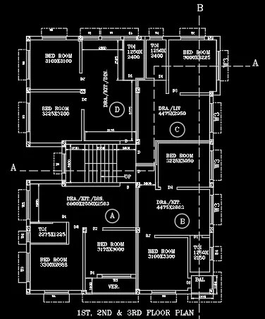
AIM: To draft the floor plan of the house and creating viewports and plot using AutoCAD
PROCEDURE:
- Open AutoCad
- Selecting metric system
- Command UN(units) and selecting decimals with precision of 0
- Command LIMITS and having limit of (0,0) in lower left corner and (10000,10000) in upper right corner
- Command ZOOM and selecting All
Commands used:
XLINE
- XLINE horizontal and vertical is used to start the drawing initally
OFFSET
- OFFSET is used to offset the external walls to 250mm and internal walls to 125mm
- OFFSET is used to offset the Bedroom to 3300mm horizontal and 2888mm vertical
- OFFSET is used to offset the Toilet to 2275mm horizontal and 1225mm vertical
- OFFSET is used to offset the Dra./Kit./Din. to 6600/2563mm horizontal and 2550 vertical
- OFFSET is used to offset the Stairs to 4400 horizontal from right offsetted bedroom and 2400 vertical
- OFFSET is used to offset the Bedroom to 3225 horizontal and 3200 vertical
- OFFSET is used to offset the Bedroom to 3100 horizontal and 3100 vertical
- OFFSET is used to offset the Dra./Kit./Din. to 3250 horizontal and 3775 vertical in the lower portion of the room and 2550 horizontal and 2525 vertical in upper portion of the room
- OFFSET is used to offset the Toilets to 1250 horizontal and 2400 vertical
- OFFSET is used to offset the Bedroom to 3000 horizontal and 3225 vertical
- OFFSET is used to offset the Dra./Liv. to 4475 horizontal and 2950 vertical
- OFFSET is used to offset the Corridor of 1000 vertical from the staircase right end
- OFFSET is used to offset the Bedroom to 3225 horizontal and 3050 vertical
- OFFSET is used to offset the Dra./Kit. to 4475mm horizontal and 2863mm vertical
- OFFSET is used to offset the Toilet to 1250mm horizontal and 2150mm vertical
- OFFSET is used to offset the Bedroom to 3100mm horizontal and 3300 vertical
- OFFSET is used to offset the Balcony to 1375mm horizontal and 1150 vertical
- OFFSET is used to offset the staircase thread to 250mm for 8 thread
- OFFSET is used to offset the Verandah to 1000mm vertical
- OFFSET is used to offset the wall to 62.5 mm 2 times to make a internal wall of dimension 125mm through out the length of the plan
- OFFSET is used to offset the different lines to specified offsetting distance
TRIM
- TRIM is used to trim the unwanted lines
PLINE
PLINE is used to draw the Column size of 250X300mm and placing it in its major axis and minor axis at the appropriate distance
LINE
- LINE is used to draw the line in the Window, Doors, Staircase and lines at required spaces and the projections of the windows at a distance of 150mm throughout
DIMLINEAR
- DIMLINEAR is used to dimension the size of the room
HATCH
- HATCH is used to hatch the column of size 250X300 by selecting the AR-CONC and changing the scale to 0.5
Annotate Tab
- In Annotate Tab ---->Modify dimension style---->Text and Style
- Changing the style from ISO25 to romanc.shx----> Set current----->Apply
TEXT
- TEXT is used to indicate the different windows like W1,W2, W3, W4 and W with height of 150mm and angle 90 degree in the vertical plane and angle of 0 degree in the horizontal plane
- TEXT is used to indicate the different windows like D1,D2 and D with height of 150mm and angle 90 degree in the vertical plane and angle of 0 degree in the horizontal plane
- TEXT is used to write the dimensions and names of the different rooms specified in the plan with height 200mm and angle 0 degree
- TEXT is used to indicate the different segment of the plan like A, B, C and D with height of 250mm and angle of 0 degree in the horizontal plane
- TEXT is used to write the 1ST, 2ND,3RD FLOOR PLAN with height 400mm and angle o degree
CIRCLE
- CIRCLE is used to encircle the different segment of the plan in a circle
LINETYPE
- LINETYPE is to change the Continuous line to Dash line and changing the scale to 20 for the projections from the windows
- LINETYPE is to change the Continuous line to Dash line and changing the scale to 30 for indicating the Section:-AA and Section:-BB in horizontal and vertical direction respectively
ERASE
- ERASE is used to erase the unwanted lines which cannot be trimmed using Trim Command
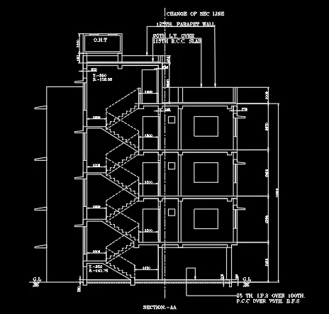
Elevation Of Section:-AA
XLINE
- XLINE horizontal and vertical is used to start the drawing initally with the projections of the wall from the Plan
OFFSET
- OFFSET is used to offset 150mm from Ground Level
- OFFSET is used to offset the Ground floor to 2450mm vertically
- OFFSET is used to offset the 1ST,2ND and 3RD floorto 2850mm vertical
- OFFSET is used to offset the Parapet wall to 1000mm vertical
- OFFSET is used to offset the Stairs to Terrace to 2500 vertical
- OFFSET is used to offset the Parapet wall to place the Over Head Tank to 450mm vertical and 600mm from stairs ceiling
- OFFSET is used to offset the ceiling to 125mm below each floor
- OFFSET is used to offset the Starting thread of the stairs from the wall at a distance of 1200mm for 1ST, 2ND and 3RD FLOOR
- OFFSET is used to offset the Starting thread of the stairs from the wall at a distance of 1450mm for GROUND FLOOR
PLINE
- PLINE is used to draw the Thread of 250mm and riser of 143.75mm of stairs in the ground floor
- PLINE is used to draw the Thread of 250mm and riser of 158.33mm of stairs in the 1ST, 2ND and 3RD floor
- PLINE is used to draw the Windows and Doors of assumed sizes
LINE
- LINE is used to draw the line in the Windows of the wall and the projections of the windows called as Chejjas at a distance of 150mm throughout the floors on both the sides with the inclined line on the upper phase
- LINE is used to draw the beam projections of the building at the suitable places where columns are placed
- With keeping Ortho OFF LINE is used to draw the Hand railings of the stairs
- With keeping Ortho OFF LINE is used to draw the symbol of G.L
LINETYPE
- LINETYPE is used to change the Continuous line to Dash line and changing the scale to 20 for the staircase
- LINETYPE is used to change the Continuous line to Longdash and short dash line and changing the scale to 30
RECTANGLE
- RECTANGLE is used to draw the Over head tank with its width 1200mm and offsetting it with 125mm
DIMLINEAR
- DIMLINEAR is used to dimension the size of the wall, stairs landing space and floor height
Annotate Tab
- In Annotate Tab ---->Modify dimension style---->Text and Style
- Changing the style from ISO25 to romanc.shx----> Set current----->Apply
TEXT
- TEXT is used to write the O.H.T with height 250mm and angle o degree
- TEXT is used to write the Section:-AA with height 300mm and angle 0 degree
MLEADERSTYLE
- Keeping arrow head size of 250 and maximum leader points to 5 and 2 and changing the text style to romanc
MLEADER
- MLEADER is used to write the description of the building
Layout
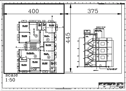
- Layout----> Page setup manager-----> New--------> Floor plan
- Printer/plotter-----> DWG to PDF.pc3-----> paper size-----> ISO A1(841.00x594.00)
- Layout----> Template----> Tutorials- mArch.dwt
- Insert Layout------> Layout name-----> ISO A1 layout----> ok
Mview
- mv-------> Selecting rectangle of size of 400 and 445
- mv-------> Selecting rectangle of size of 375 and 445
- ms-------> Working in the model space
- ps--------> Working in the paper space
- selecting scale in the respective mv of 1:50
ATTEDIT
- Attedit is used to edit the attributes that are created and giving the appropriate values for the Templates
Result
Challenge 2:
Aim: To draft the floor plan of the house and creating viewport and plots using AutoCAD
Procedure:
- Open AutoCad
- Selecting metric system
- Command UN(units) and selecting decimals with precision of 0
- Command LIMITS and having limit of (0,0) in lower left corner and (10000,10000) in upper right corner
- Command ZOOM and selecting All
Commands used:
XLINE
- XLINE horizontal and vertical is used to start the drawing initally
LINE
- LINE is used to draw the line in the Window and Doors at required spaces
OFFSET
Sketching below counter plan
- OFFSET is used to offset the external walls to 230mm
- OFFSET is used to offset the Working platform 1 for 1000, 600, 450, 300, 900, 945 and 35 respectively in horizontal direction
- OFFSET is used to offset the Working platform 1 for 600mm vertically
- OFFSET is used to offset the Working platform 2 for 35, 900, 450, 900, 450, 450, 450, 560 and 35 respectively in horizontal direction
- OFFSET is used to offset the Working platform 2 for 600mm vertically
- OFFSET is used to offset the 700 mm from right wall horizontally and 900 mm vertically for snack counter
- OFFSET is used to offset 12mm on both sides to the main offsetted line to dimension it center to center
Sketching above counter plan
- OFFSET is used to offset the external walls to 230mm
- OFFSET is used to offset the Working platform 1 for 35, 965, 600, 2595 and 35 respectively in horizontal direction
- OFFSET is used to offset the Working platform 1 for 600 and 350 mm in vertical direction
- OFFSET is used to offset the Working platform 2 for 35, 450, 900, 900, 900, 1010 and 35 respectively in horizontal direction
- OFFSET is used to offset the Working platform 2 for 350mm in vertical direction
- OFFSET is used to offset 12mm on both sides to the main offsetted line to dimension it center to center
PLINE
- PLINE is used to draw the fridge, Micro oven, Hob, sink and Chimney both in below and above counter plan
DDptype
- Changing the points to visible points to divide the line
DIVIDE
- Dividing the 2595 line into 3 equal parts
DIMBREAK
- DIMBREAK is used to break the dimensions which are crossing each other in snack counter 900mm dimension line is breaked from 450mm line
TRIM
- TRIM is used to trim the unwanted lines
CIRCLE
- CIRCLE is used to draw the Sink hole, Snack counter ,hob and Chimney
ARC
- ARC is used to draw the doors with Start,Center and End
LINETYPE
- LINETYPE is to change the Continuous line to Dash line and changing the scale to 20
Annotate Tab
- In Annotate Tab ---->Modify dimension style---->Text and Style
- Changing the style from ISO25 to Romanc.shx----> Set current----->Apply
DIMLINEAR
- DIMLINEAR is used to dimension the working platform 1 and 2
DIMCONTINUE
- DIMCONTINUE is used to dimension quickly using after DIMLNEAR command for working platforms
TEXT
- TEXT is used to write the name of the electronic items at the specified location like Fridge, Micro oven etc
- TEXT is used to write the dimensions of different compartment like A1 to A15
ERASE
- ERASE is used to erase the unwanted lines which cannot be trimmed using Trim Command
Layout
- Layout----> Page setup manager-----> New--------> Kitchen plan
- Printer/plotter-----> DWG to PDF.pc3-----> paper size-----> A4(210.00x297.00)
Mview
- mv-------> Selecting 4
- ms-------> Working in the model space
- ps--------> Working in the paper space
- selecting scale in the respective mv of 1:1 and 1:2
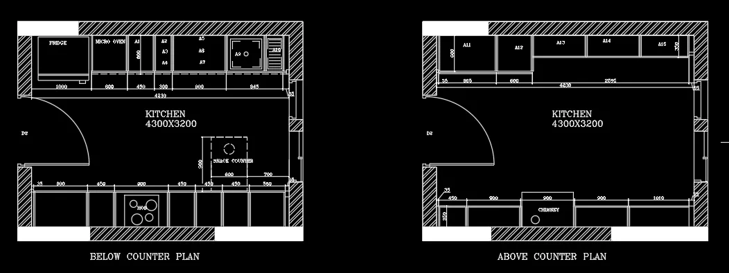
Result
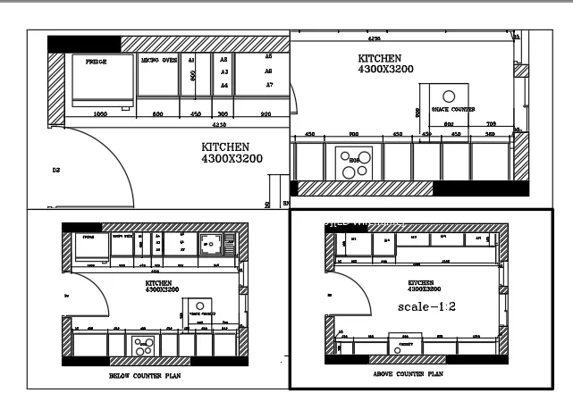
Challenge 3
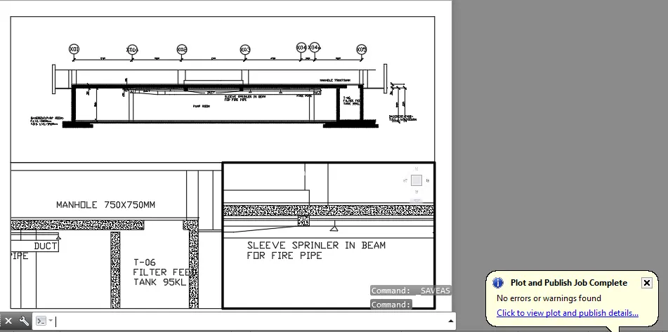
AIM: To draft the floor plan of the Industrial building and creating viewports and plot using AutoCAD
PROCEDURE:
- Open AutoCad
- Selecting metric system
- Command UN(units) and selecting decimals with precision of 0
- Command LIMITS and having limit of (0,0) in lower left corner and (10000,10000) in upper right corner
- Command ZOOM and selecting All
Commands used:
PLINE
- PLINE is used to draw the sectional view of industrial building
LINETYPE
- LINETYPE is to change the Continuous line to Dotted line and changing the scale to 20
RECTANGLE
- RECTANGLE is used to draw the ducts
LINE
- LINE is used to draw the line in the ducts of industrial building
Annotate Tab
- In Annotate Tab ---->Modify dimension style---->Text and Style
- Changing the style from ISO25 to Romanc.shx----> Set current----->Apply
DIMLINEAR
- DIMLINEAR is used to dimension the size of building from G.L
TEXT
- TEXT is used to write the PUMP ROOM with height 250mm and angle o degree
- TEXT is used to write the BASEMENT with height 300mm and angle 0 degree
HATCH
- HATCH is used to hatch area by solid
- HATCH is used to hatch area by AR-CONC
MLEADERSTYLE
- MLEADERSTYLE-----> content----> mleader type-----> Block----> source block---->circle
MLEADER
- MLEADER is used to leader the vertical lines as X01,X01a,X02,X03,X04,X04a and X05
Layout
- Layout----> Page setup manager-----> New--------> Kitchen plan
- Printer/plotter-----> DWG to PDF.pc3-----> paper size-----> A4(210.00x297.00)
Mview
- mv-------> Selecting 3-------> above
- ms-------> Working in the model space
- ps--------> Working in the paper space
- selecting scale in the respective mv of 1:100 and 1:30
PLOT
- Plot---->Printer/plotter-----> DWG to PDF.pc3-----> paper size-----> A4(210.00x297.00)
- Save in the desired folder
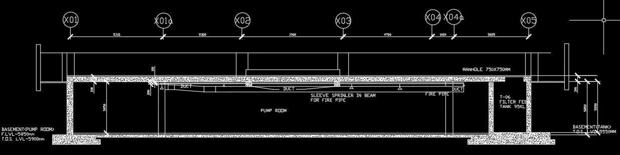
Result