AutoCAD_Layout of Kitchen Cabinet, Elevation of a Residential Building and Industrial Building section_Week 9
Challenge 1
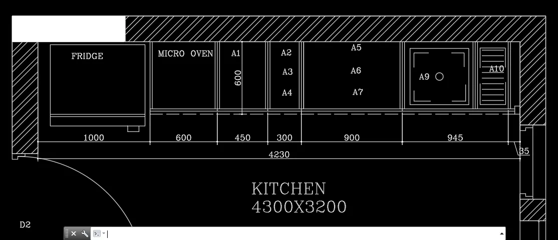
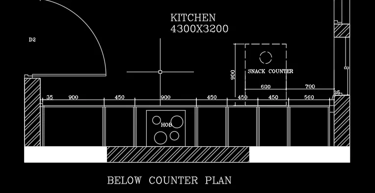
KITCHEN PLAN
Aim: To draft the floor plan of the Kitchen and hatching it using AutoCAD
Procedure:
- Open AutoCad
- Selecting metric system
- Command UN(units) and selecting decimals with precision of 0
- Command LIMITS and having limit of (0,0) in lower left corner and (10000,10000) in upper right corner
- Command ZOOM and selecting All
Commands used:
XLINE
- XLINE horizontal and vertical is used to start the drawing initally
LINE
- LINE is used to draw the line in the Window and Doors at required spaces
OFFSET
Sketching below counter plan
- OFFSET is used to offset the external walls to 230mm
- OFFSET is used to offset the Working platform 1 for 1000, 600, 450, 300, 900, 945 and 35 respectively in horizontal direction
- OFFSET is used to offset the Working platform 1 for 600mm vertically
- OFFSET is used to offset the Working platform 2 for 35, 900, 450, 900, 450, 450, 450, 560 and 35 respectively in horizontal direction
- OFFSET is used to offset the Working platform 2 for 600mm vertically
- OFFSET is used to offset the 700 mm from right wall horizontally and 900 mm vertically for snack counter
- OFFSET is used to offset 12mm on both sides to the main offsetted line to dimension it center to center
Sketching above counter plan
- OFFSET is used to offset the external walls to 230mm
- OFFSET is used to offset the Working platform 1 for 35, 965, 600, 2595 and 35 respectively in horizontal direction
- OFFSET is used to offset the Working platform 1 for 600 and 350 mm in vertical direction
- OFFSET is used to offset the Working platform 2 for 35, 450, 900, 900, 900, 1010 and 35 respectively in horizontal direction
- OFFSET is used to offset the Working platform 2 for 350mm in vertical direction
- OFFSET is used to offset 12mm on both sides to the main offsetted line to dimension it center to center
PLINE
- PLINE is used to draw the fridge, Micro oven, Hob, sink and Chimney both in below and above counter plan
DDptype
- Changing the points to visible points to divide the line
DIVIDE
- Dividing the 2595 line into 3 equal parts
DIMBREAK
- DIMBREAK is used to break the dimensions which are crossing each other in snack counter 900mm dimension line is breaked from 450mm line
TRIM
- TRIM is used to trim the unwanted lines
CIRCLE
- CIRCLE is used to draw the Sink hole, Snack counter ,hob and Chimney
ARC
- ARC is used to draw the doors with Start,Center and End
LINETYPE
- LINETYPE is to change the Continuous line to Dash line and changing the scale to 20
Annotate Tab
- In Annotate Tab ---->Modify dimension style---->Text and Style
- Changing the style from ISO25 to Romanc.shx----> Set current----->Apply
DIMLINEAR
- DIMLINEAR is used to dimension the working platform 1 and 2
DIMCONTINUE
- DIMCONTINUE is used to dimension quickly using after DIMLNEAR command for working platforms
HATCH
- HATCH is used to hatch area by Solid
- HATCH is used to hatch area by ANS132
TEXT
- TEXT is used to write the name of the electronic items at the specified location like Fridge, Micro oven etc
- TEXT is used to write the dimensions of different compartment like A1 to A15
ERASE
- ERASE is used to erase the unwanted lines which cannot be trimmed using Trim Command
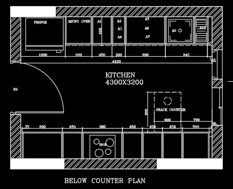
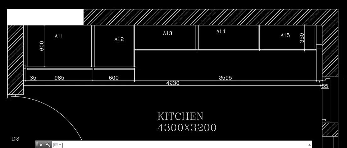
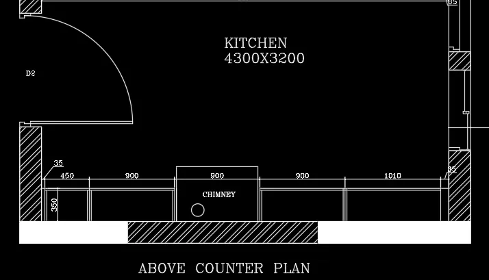
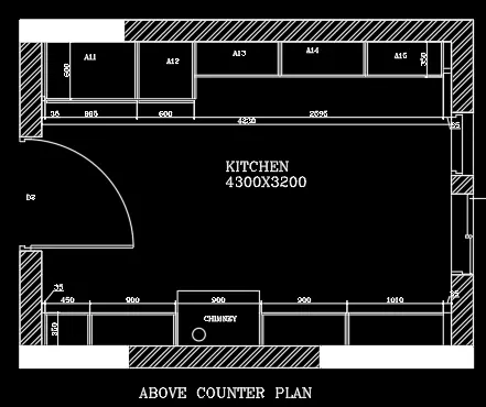
Result
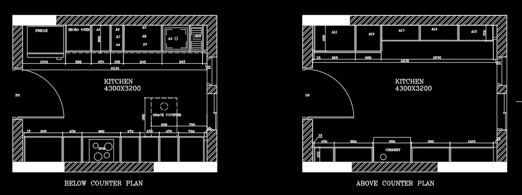
Challenge 2
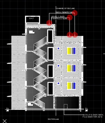
Elevation Of Section:-AA
Aim: To draft the Elevation of the floor plan and hatching it using AutoCAD
Procedure:
- Open AutoCad
- Selecting metric system
- Command UN(units) and selecting decimals with precision of 0
- Command LIMITS and having limit of (0,0) in lower left corner and (10000,10000) in upper right corner
- Command ZOOM and selecting All
Commands used:
XLINE
- XLINE horizontal and vertical is used to start the drawing initally with the projections of the wall from the Plan
OFFSET
- OFFSET is used to offset 150mm from Ground Level
- OFFSET is used to offset the Ground floor to 2450mm vertically
- OFFSET is used to offset the 1ST,2ND and 3RD floorto 2850mm vertical
- OFFSET is used to offset the Parapet wall to 1000mm vertical
- OFFSET is used to offset the Stairs to Terrace to 2500 vertical
- OFFSET is used to offset the Parapet wall to place the Over Head Tank to 450mm vertical and 600mm from stairs ceiling
- OFFSET is used to offset the ceiling to 125mm below each floor
- OFFSET is used to offset the Starting thread of the stairs from the wall at a distance of 1200mm for 1ST, 2ND and 3RD FLOOR
- OFFSET is used to offset the Starting thread of the stairs from the wall at a distance of 1450mm for GROUND FLOOR
PLINE
- PLINE is used to draw the Thread of 250mm and riser of 143.75mm of stairs in the ground floor
- PLINE is used to draw the Thread of 250mm and riser of 158.33mm of stairs in the 1ST, 2ND and 3RD floor
- PLINE is used to draw the Windows and Doors of assumed sizes
LINE
- LINE is used to draw the line in the Windows of the wall and the projections of the windows called as Chejjas at a distance of 150mm throughout the floors on both the sides with the inclined line on the upper phase
- LINE is used to draw the beam projections of the building at the suitable places where columns are placed
- With keeping Ortho OFF LINE is used to draw the Hand railings of the stairs
- With keeping Ortho OFF LINE is used to draw the symbol of G.L
LINETYPE
- LINETYPE is used to change the Continuous line to Dash line and changing the scale to 20 for the staircase
- LINETYPE is used to change the Continuous line to Longdash and short dash line and changing the scale to 30
RECTANGLE
- RECTANGLE is used to draw the Over head tank with its width 1200mm and offsetting it with 125mm
DIMLINEAR
- DIMLINEAR is used to dimension the size of the wall, stairs landing space and floor height
Annotate Tab
- In Annotate Tab ---->Modify dimension style---->Text and Style
- Changing the style from ISO25 to romanc.shx----> Set current----->Apply
TEXT
- TEXT is used to write the O.H.T with height 250mm and angle o degree
- TEXT is used to write the Section:-AA with height 300mm and angle 0 degree
HATCH
- HATCH is used to hatch area by Solid
- HATCH is used to hatch area by AR-BRSTD for wall
- HATCH is used to hatch area by selecting gradient of double colour to window
- HATCH is used to hatch area by AR-CONC to staircase
- HATCH is used to hatch area by selecting gradient of single colour for Door
MLEADERSTYLE
- Keeping arrow head size of 250 and maximum leader points to 5 and 2 and changing the text style to romanc
MLEADER
- MLEADER is used to write the description of the building
Result
Challenege 3
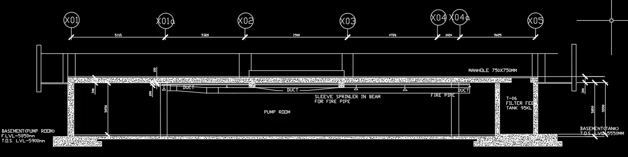
Aim: To draft the Industrial floor plan and hatching it using AutoCAD
Procedure:
- Open AutoCad
- Selecting metric system
- Command UN(units) and selecting decimals with precision of 0
- Command LIMITS and having limit of (0,0) in lower left corner and (10000,10000) in upper right corner
- Command ZOOM and selecting All
Commands used:
PLINE
- PLINE is used to draw the Sectional view of the Industrial Building
LINE
- LINE is used to draw the line in the Ducts of the Industrial building
LINETYPE
- LINETYPE is used to change the Continuous line to Dotted and changing the scale to 20
RECTANGLE
- RECTANGLE is used to draw the ducts
DIMLINEAR
- DIMLINEAR is used to dimension the size of the Building from the G.L
Annotate Tab
- In Annotate Tab ---->Modify dimension style---->Text and Style
- Changing the style from ISO25 to romanc.shx----> Set current----->Apply
TEXT
- TEXT is used to write the PUMP ROOM with height 250mm and angle o degree
- TEXT is used to write the BASEMENT With Height 250mm and angle 0 degree
HATCH
- HATCH is used to hatch area by Solid
- HATCH is used to hatch area by AR-CONC
MLEADERSTYLE
- MLEADERSTYLE-----> content----> mleader type-----> Block----> source block---->circle
MLEADER
- MLEADER is used to leader the vertical lines as X01,X01a,X02,X03,X04,X04a and X05
Result