Introduction to REVIT concepts
AIM : To learn basic concepts of REVIT software
INTRODUCTION :
Revit is a building information modeling software from autodesk which is used in architectural design, structural engineering, MEP engineering and construction. This software is user friendly and used to to make 3D design, analysis, optimization and real visualization accurately.
Benefits of revit
- Realtime 3D modelling programme
- Evaluates performance
- Optimization
- Sustainability
- Parametric design
Revit in various disciplines
- Architectural design - To visualize the project with different design solutions
- Structural engineering - To model 3D reinforcement designs and conduct structural analysis
- MEP engineering - MEP stands for mechanical, electrical and plumbing and revit is used to model building systems and analyse its performance. Example - Duct and pipe system modeling, HVAC and electrical system design, duct/pipe sizing and pressure calculators, conduit and cable modeling etc
- Construction - To make preconstruction decisions which helps to minimise constructability risks and documentation of concrete designs
Collaboration tools in revit offers to work all these users simultaneously
Limitations
Revit avoids duplicate elements and creates no repetition.
Revit avoids uncertainity in modeling.
QUESTION 1
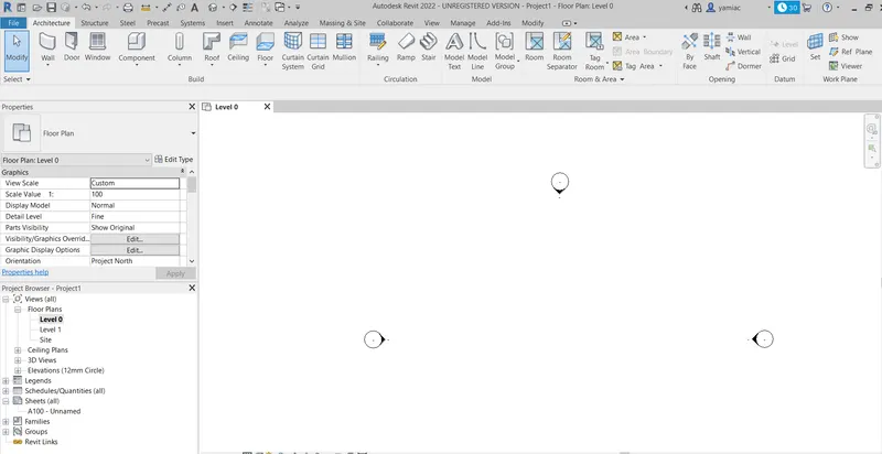
AIM : To create a new project (Structural / Architectural / Construction template ) and name the project appropriately
PROCEDURE :
- Open REVIT software
- Click on new
- Select template
- Architectural template is selected
(OR)
- Click on file and select new
- Select project
- Select template
- Architectural template is selected
RESULT : New file is created
QUESTION 2
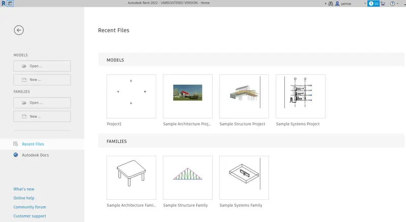
AIM : To save the new project file and open using icons from file toolbar
PROCEDURE :
- Save the file as "Project1"
- Close the file and open by clicking on project1 in models saved
RESULT : Project file is saved
QUESTION 3 :
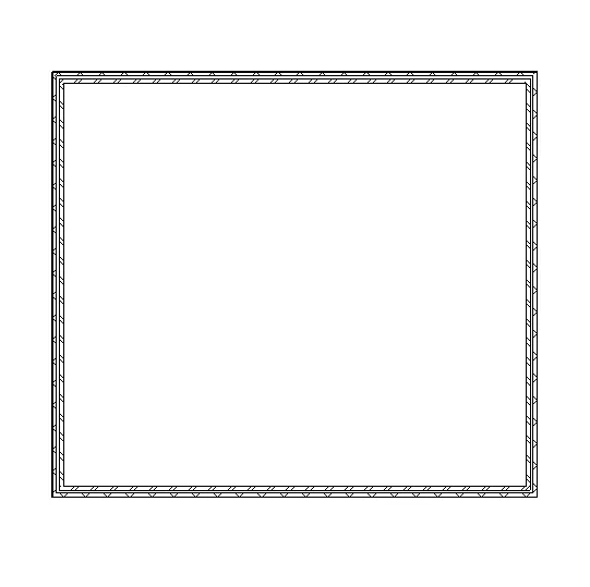
AIM : To create a rectangular layout of walls of about 40’-0” X 35’-0”
PROCEDURE :
- In project1, set units by typing "UN"
- Select length and select units to feet
- Click on architecture tab
- Click on wall tool
- Now click on screen
- Move the cursor towards left and enter distance 40'
- Next continue to move the cursor upwardsand enter distance 35'
- And the continue to move the cursor towards left and enter distance 40'
- Close the wall by clicking on starting point
RESULT : 40' X 35' wall is created
QUESTION 4 :
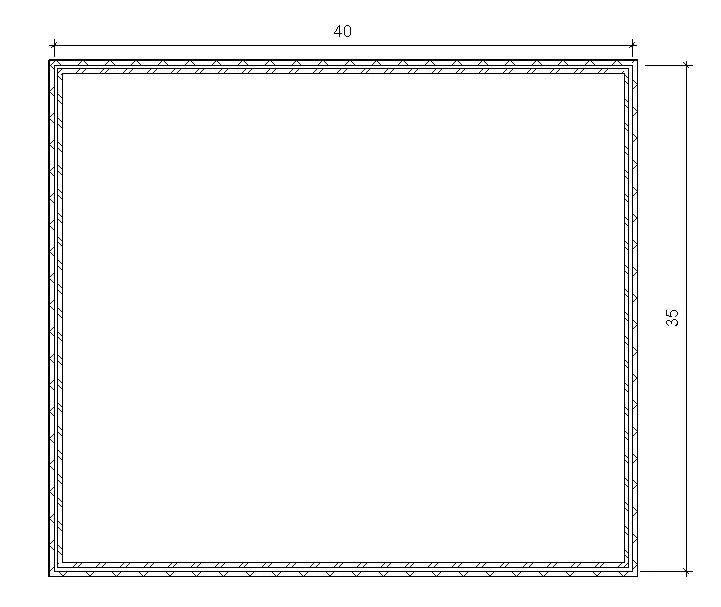
AIM : To add dimensions to wall using aligned option
PROCEDURE :
- In project1, click on annotate tab
- Click on aligned tool
- Mention dimensions of wall
RESULT : Dimensions of the wall is marked
QUESTION 5 :
AIM : To create different wall types using properties browser
PROCEDURE :
- Open project1, select any side of the wall created
- Go to properties browser which is present at left side and select different types of walls
RESULT : Different walls are assigned
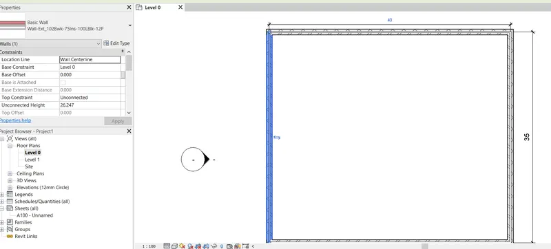
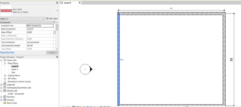
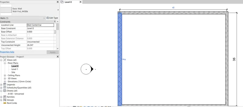
QUESTION 6 :
AIM : To create a 3D view of the wall and save the view with the appropriate name
PROCEDURE :
- Open project1
- Click on view tab
- Click on 3D view
- Save the view as wall
RESULT : 3D View is created
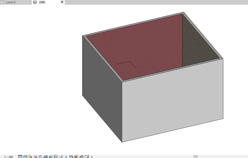
QUESTION 7 :
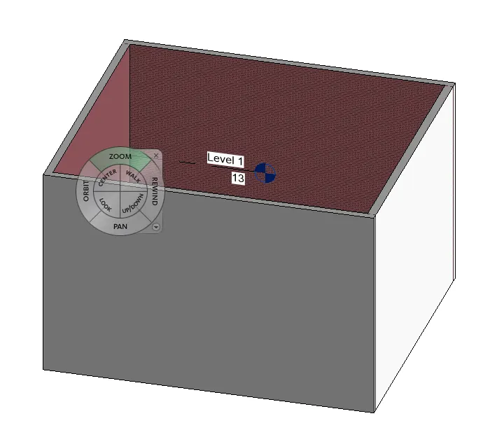
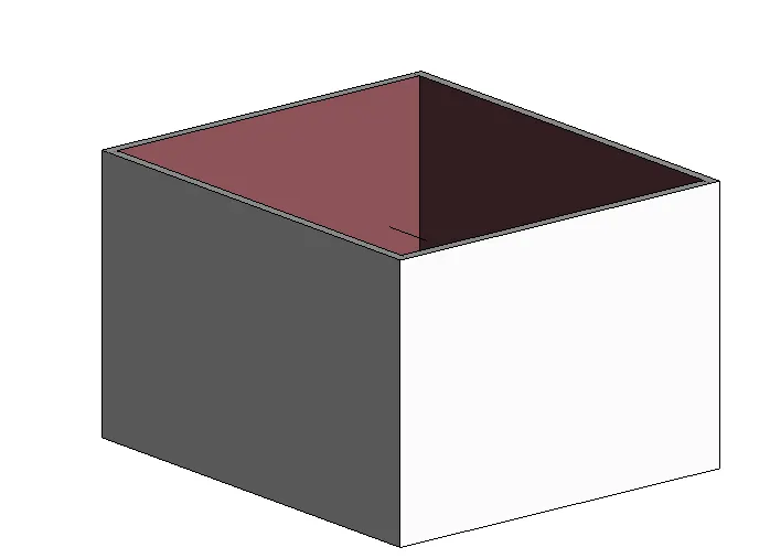
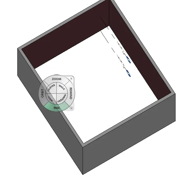
AIM : To navigate through the 3D model using the view cube
PROCEDURE :
- Open project1
- Click on full navigation wheel tool present on the right side
- Click on orbit / pan and rotate wall in different directions
RESULT : Navigation of wall in different directions
QUESTION 8 :
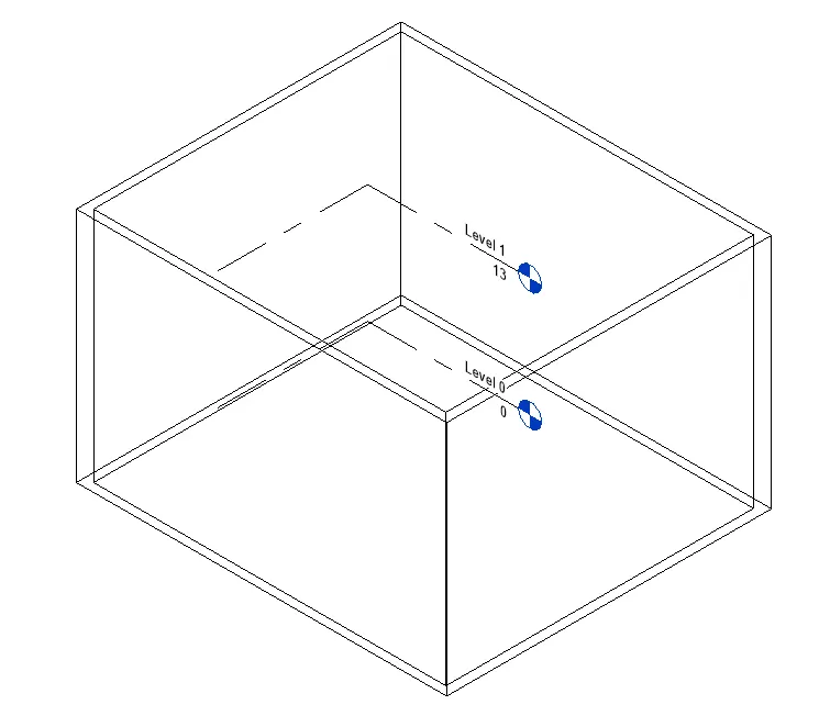
AIM : To switch model to shaded, realistic, hidden lines options present in visibility settings
PROCEDURE :
- Open project1
- Click on visual styles present at bottom of the screen
- Change to different styles such as : wireframe/hiddenline/shaded/consistent colours/realistic
- Save each view
RESULT : Different visual styles are created
Wireframe
Hiddenline
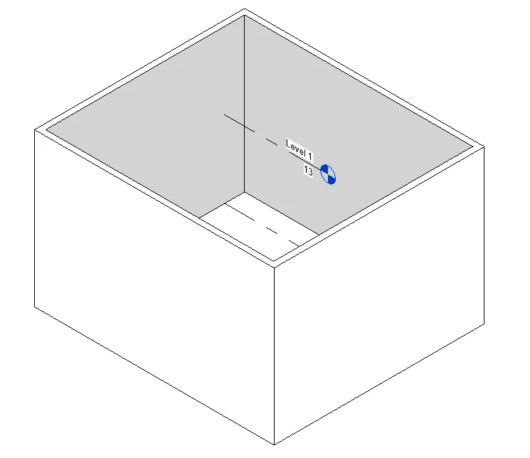
Shaded
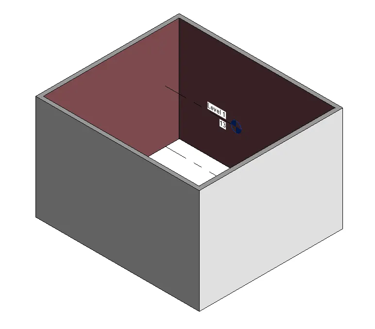
Consistent colours
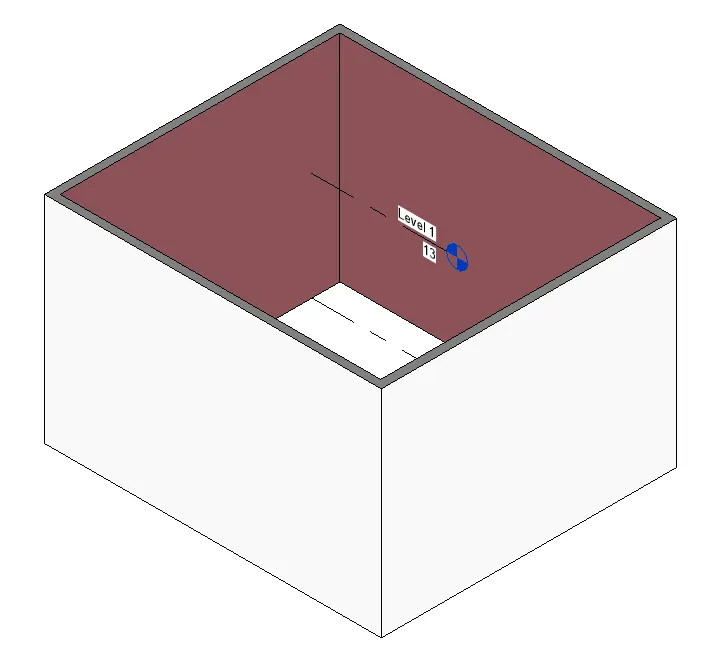
Realistic
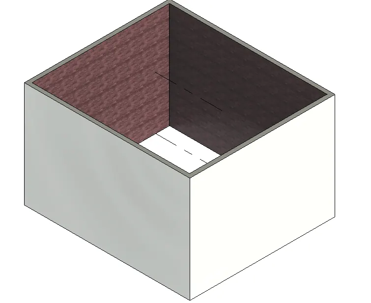
QUESTION 9 :
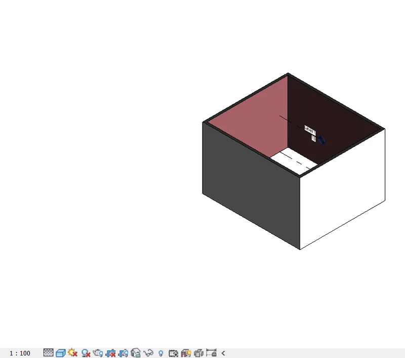
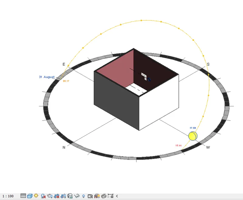
AIM : To turn the sun path on and off to view shadings in the layout created
PROCEDURE :
- Open project1
- Click on sun symbol present beside visual style
- Turn on the sun path
- Go to sun settings and select still, Press ok
RESULT : With and Without sunpath view created
Without sunpath
With sun path
QUESTION 10 :
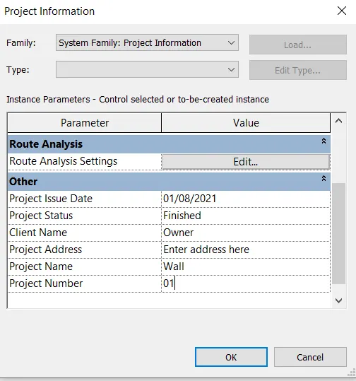
AIM : To create project name, and project issue date using manage toolbars
PROCEDURE :
- Open project1
- Click on manage toolbar
- Click on project information
- Enter Project issue date as : 01/08/2021
- Enter Project status as : Finished
- Enter Project name : Wall
- Enter project no : 01
- Press ok
RESULT : Project information is created
QUESTION 11 : What is the Analyze toolbar used in Revit? How it is beneficial for design and modeling ?
Answer : Use of analyze toolbar in Revit and its benefits for design and modeling
To evaluate performance of the project using boundary conditions and loads. Different load combination are applied and revit analysis these loads, thus giving efficient load combination for the building. Therefore it can analyse conceptual design in several ways such as area analysis, energy analysis, heating and cooling loads analysis and analyse effects of structural loads. Energy analytical model is based on conceptual mass, building elements or on both depending on analysis mode. Heating and cooling loads analysis is performed to determine energy demands of the building. Sustainability is crucial now a days in construction process, energy optimization in revit is useful to maintain sustainability of the design.
QUESTION 12 : What are the links that Revit supports to be linked to the model ?
Answer : Links that Revit supports
Link Revit : Linking another revit model to current model
Link IFC : Links IFC file to current project. IFC enable interoperability between different software as it has international standards to import and export building elements
Link CAD : Links CAD to current revit project. Linking is similar to having an xref in AutoCAD
Link Topography : Links of existing topography to the current revit model. Topography created in software such as autodesk civil 3D
DWF Markup : Links marked up DWF files into a revit project to see markups on corresponding sheets
Point cloud : Links point cloud file ( .rcp or .rcs) into current project. It provides references for placing or editing model elements
Coordination model : Links NWD or NWC file to provide context for revit model
Link PDF and Link Image to revit
QUESTION 13 : Why do you need the Collaborate tab in Revit? How it supports modeling and its efficiency ?
Answer : Need for collaboration tool in Revit and its efficiency
Collaboration tool offers users such as structural engineer and MEP engineers to work simultaneously. It enables cloud file, collaborate with it with multiple instances of independent files. It creates complete building model by bringing different models together. It enables to understand changes in the model and any conflicts occuring in the design when it is linked together. Thus it enables to design an optimized and efficient building model. Suppose to link revit file to current file (structural file), make a copy of current file and name it as MEP file. Link both the files and thus it enables to work on both files simultaneously.