Introduction to REVIT concepts
Challenge Week 1
1. Aim: Create a new project and name the project appropriately.
Procedure:
1. Click on the File menu>New>Project.
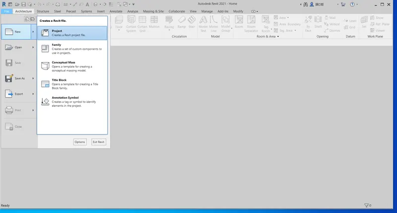
2. Select the desired Template such as Architectural/Construction/Structural in Imperial or Metric system.
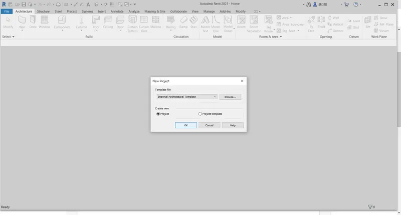
2. Aim: Save the new project file. Close and open using icons from the file toolbar.
Procedure:
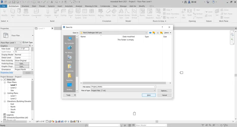
1. Click on the File menu>Save As.
2. Give the project a suitable name and click on save. The project is now saved in the selected drive and folder.
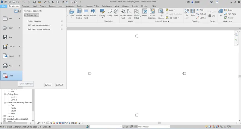
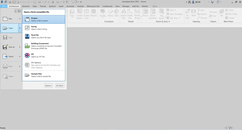
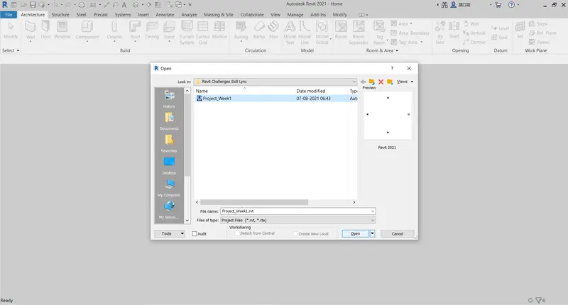
3. We can close and open any project from the File menu tab.
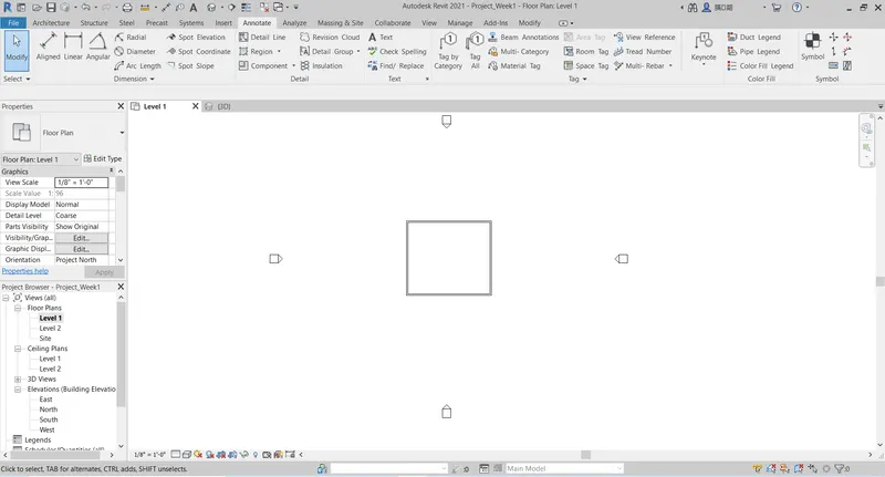
3. Aim: From the architecture/structure toolbar familiarize with options to draw a wall. Create a rectangular
layout of walls of about 40’-0” X 35’-0”.
Procedure:
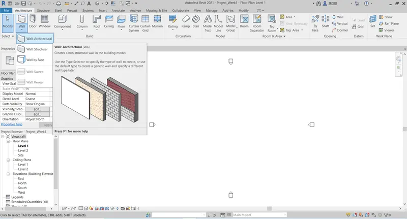
1. In the Architecture Tab move the mouse pointer over the Wall icon > Select the wall type to be created.
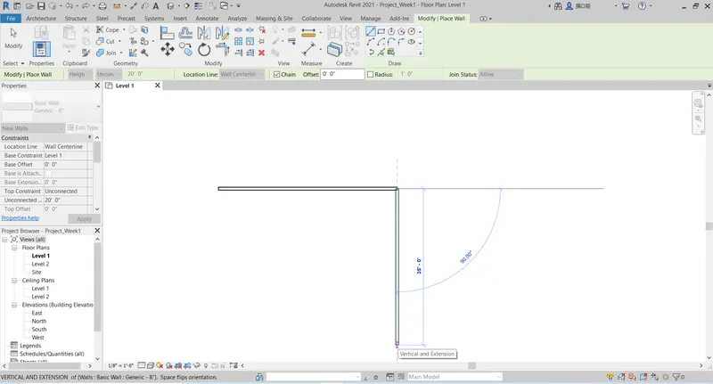
2. Now draw the rectangular wall layout of 40' x 35'.
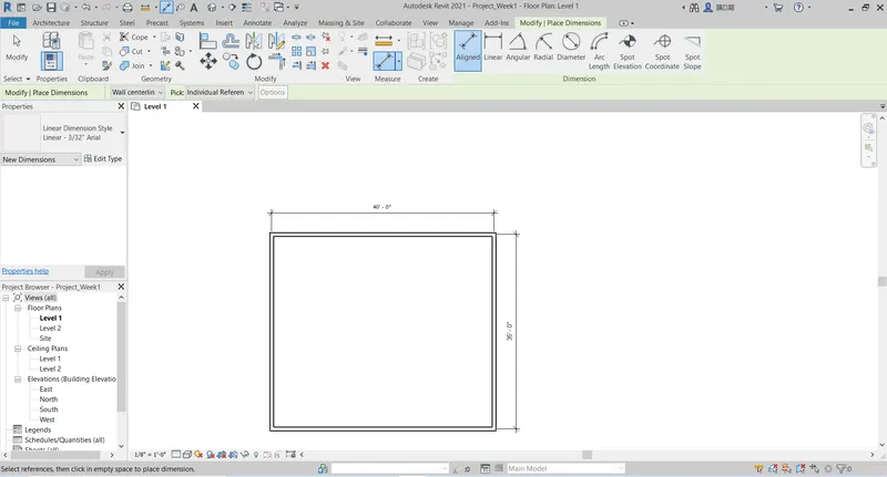
4. Aim: From the Annotate toolbar use the aligned option to add dimensions to the layout.
Procedure:
1. In the Annotate Tab click on the Aligned icon and then select the points between which the dimensions have to be
defined.
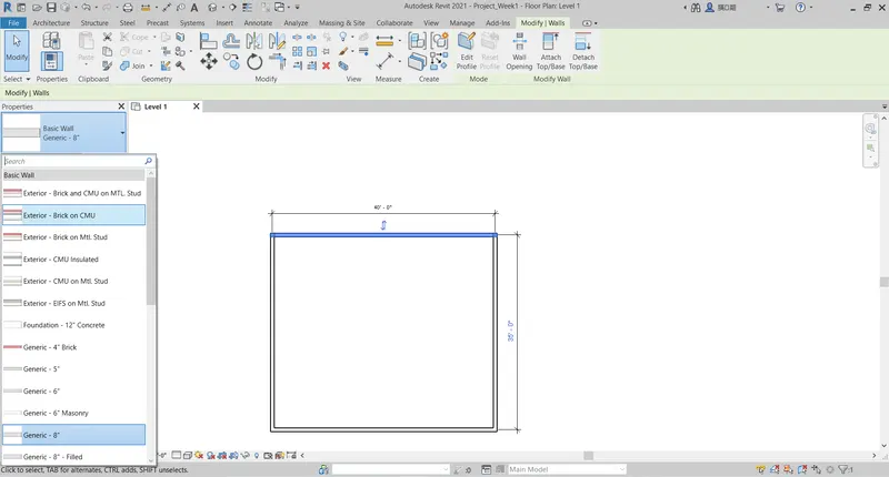
5. Aim: Use the properties browser to switch to different wall types.
Procedure:
1. Click on the properties browser to select any wall type as per the project's requirements.
6. Aim: Create a 3D view from the view toolbar and save the view with the appropriate name.
Procedure:
1. Click on the 3D view icon in the View tab to turn the view from 2D to 3D.
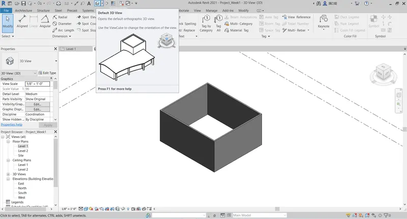
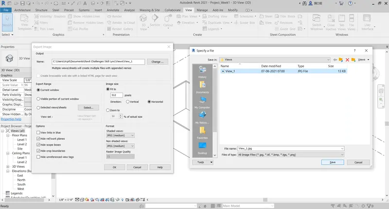
2. Now click on File > Export > Images and Animations > Images.
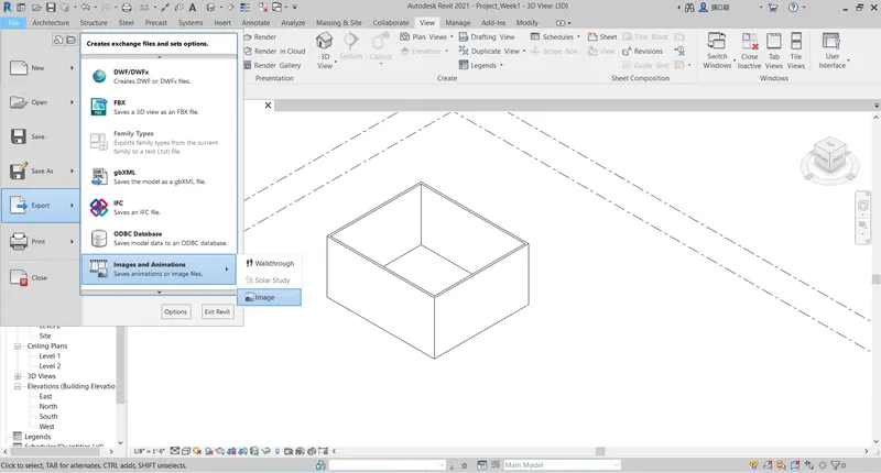
3. Now give a name to the view and save the image on the local computer.
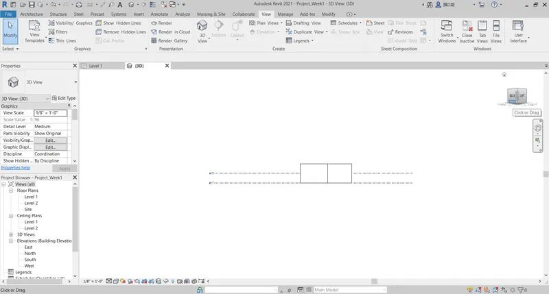
7. Aim: Navigate through the 3D model using the view cube. Orbit/pan through the model layout created.
Procedure:
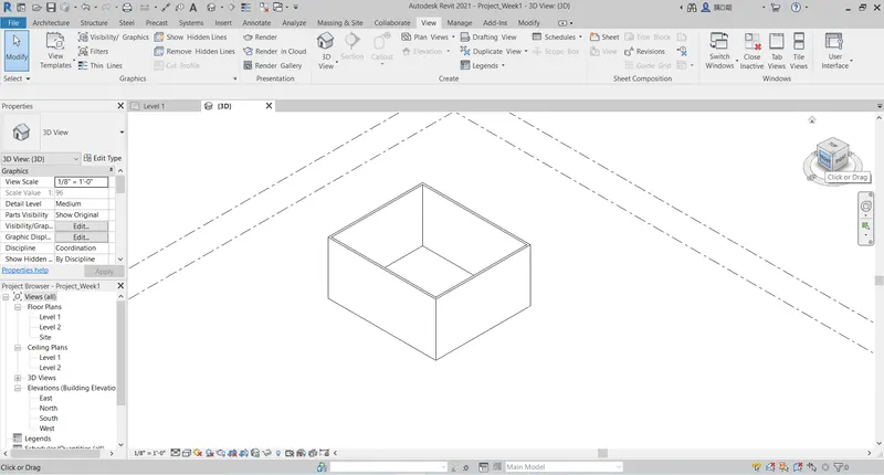
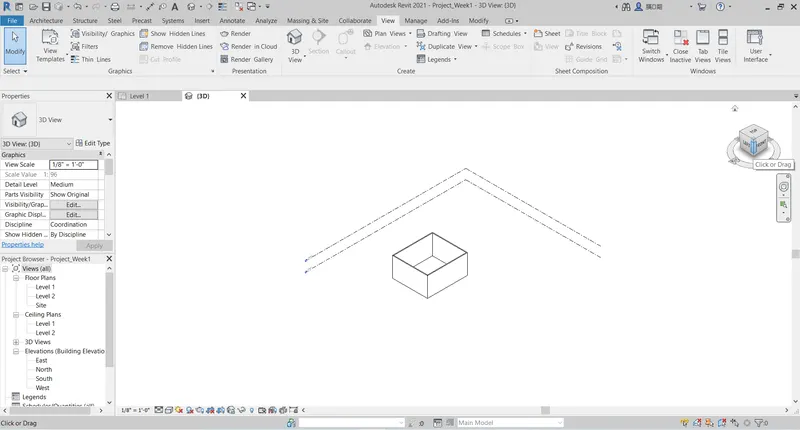
1. Move the mouse pointer on the view cube. Select the surface on the view cube icon and click.
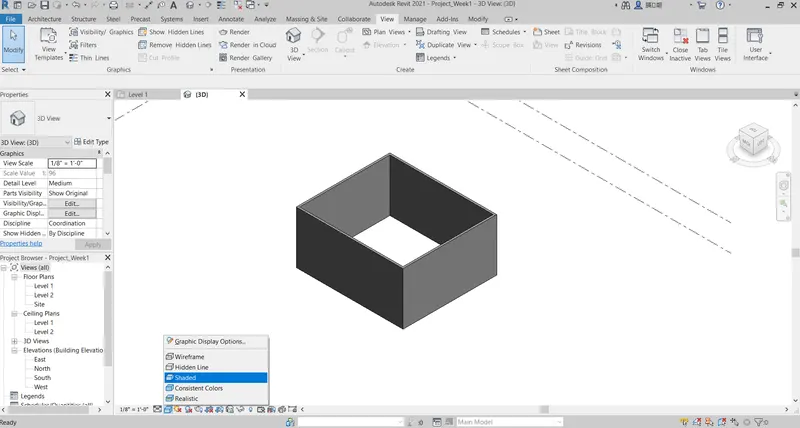
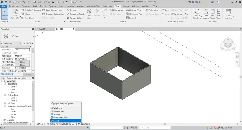
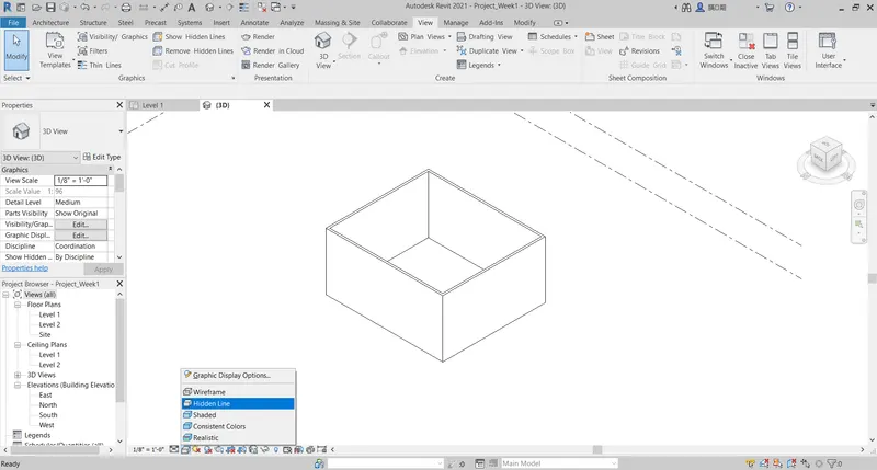
8. Aim: Use the visibility settings option below to switch model to shaded, realistic, hidden lines options.
Procedure:
1. Click on the cube icon on the visibility settings toolbar present just below the workspace. Select the desired visibility
option and click.
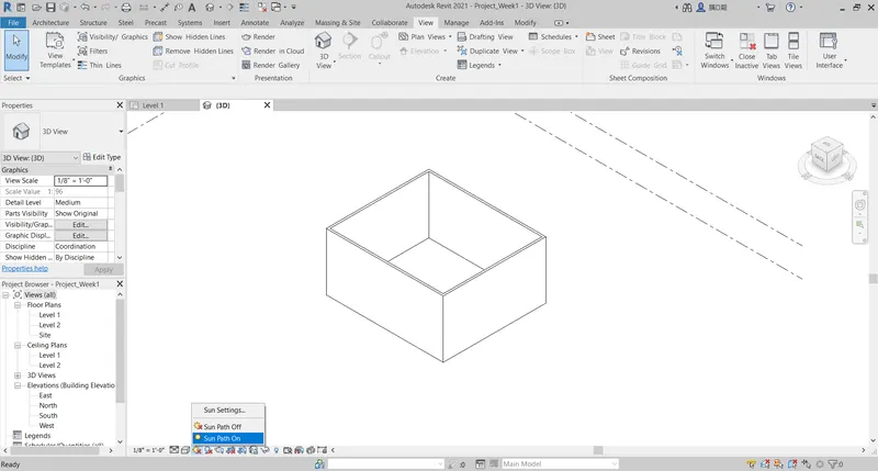
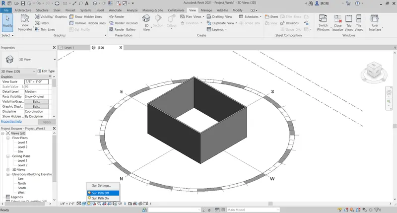
9. Aim: Turn the sun path on and off to view shadings in the layout created.
Procedure:
1. Click on the sun icon on the visibility settings toolbar present just below the workspace. Select the on or off option and
click to toggle the sun path visibility.
10. Aim: Use the Manage toolbar to enter project settings, project name, and project issue date (choose
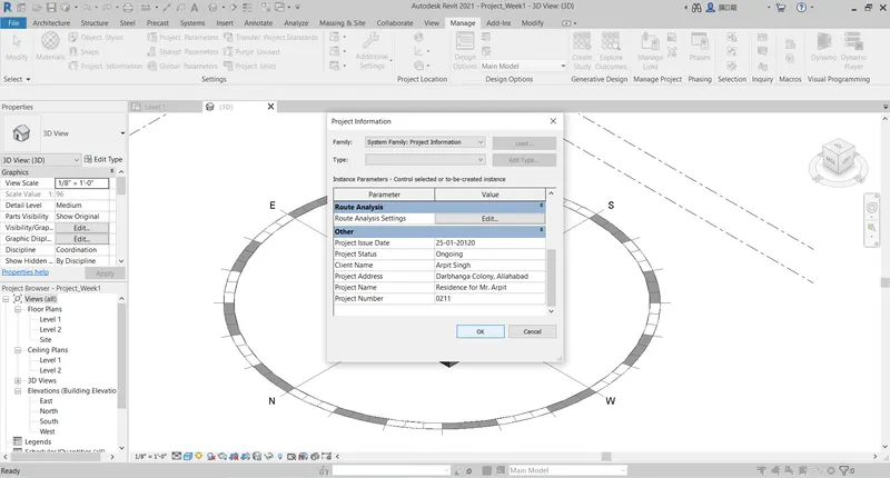
according to your convenience).
Procedure:
1. Click on the Project Information option under the Manage tab. A dialog box appears. Now we can input the project
related information in it.
11. What is the Analyze toolbar used in Revit? How it is beneficial for design and modeling.
Ans. The Analyze toolbar in Revit is used to analyze and evaluate the building performance based on various parameters.
a. It is used to evaluate the building's structural performance as per the loading conditions given to it and various other
inputs.
b. It is also used to evaluate the building's energy performance based on its geographic loaction. After analysis it can
also be used to optimise the energy performance.
c. It can be used by the mechnaical engineers to calculate the heating and cooling loads for the building.
d. It can also be used by engineers to calculate water pressures in piping systems of the structure.
e. It can also generate schedules and/or quantities of materials used in the structure based on the model's properties.
The Analyze toolbar is beneficial for design and modeling since we are able to analyze the structure through various
disciplin angles and are able to produce an efficient model of the structure.
12. What are the links that Revit supports to be linked to the model?
Ans. Revit supports a variety of functions such as
a. Linking the revit model to another revit model.
b. Linking a CAD file (2D) such as of a plan so it can be referred there in the model itself to generate the 3D structure.
c. Sharing a single revit file with other disciplins such as systems engineer, plumbing, electrical, structural in the form
of a central file which can be accessed and modified by each disciplin as per their requirements and the file loaded on
the local systms can be updated to load all the recent changes by any of the disciplins.
d. Geographic location can also be linked to the revit model which is required for accurate energy performance review
and optimisation.
13. Why do you need the Collaborate tab in Revit? How it supports modeling and its efficiency.
Ans. The collaborate feature of Revit provides easy linking and sharing options and also gives access to all the controls
over such sharing.
a. It ensures members from different disciplins can work together on a shared central file from their respective work
places simultaneously.
b. They have the control to link or unlink any file as per their requirements.
c. The development or modifications of all the disciplins on the model reflects in real time and so it becomes quite
beneficial in terms of efficiency, since a lot of co-ordinated work can be done effortlessly in lesser time.
d. Proper co-ordination among the designers, engineers, and other stakeholders results in an efficient outcome in terms
of cost and time to be invested in the project.