Introduction to REVIT concepts
1) AIM:
To create a new project (Structural/Architectural/Construction template) and naming the project appropriately.
INTRODUCTION:
Revit is a BIM software helping architectural, engineering, and construction (AEC) teams to create high-quality buildings and infrastructure.
We use Revit to
- Model shapes, structures, and systems in 3D with parametric accuracy, precision, and ease.
- Streamline documentation work, with instant revisions to plans, elevations, schedules, and sections as projects change.
- Empower multidisciplinary teams with specialty toolsets and a unified project environment.
PROCEDURE:
First start the revit software.
From the model tab click NEW.
A new dialogue box will appear on the screen.Click on the desired template.
In the template file> ARCHITECTURAL TEMPELATE.
Create new project.
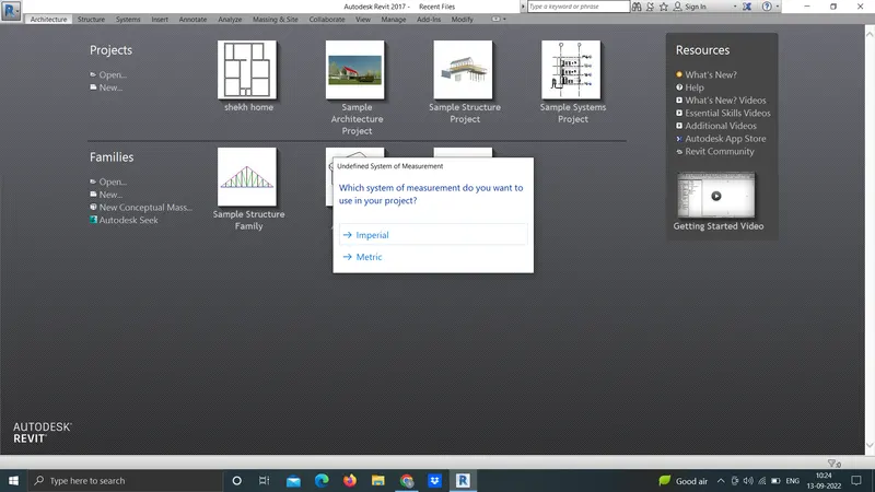
Press OK.
A new workspace will be loaded.
Go to file menu>save>rename the file as Project 2
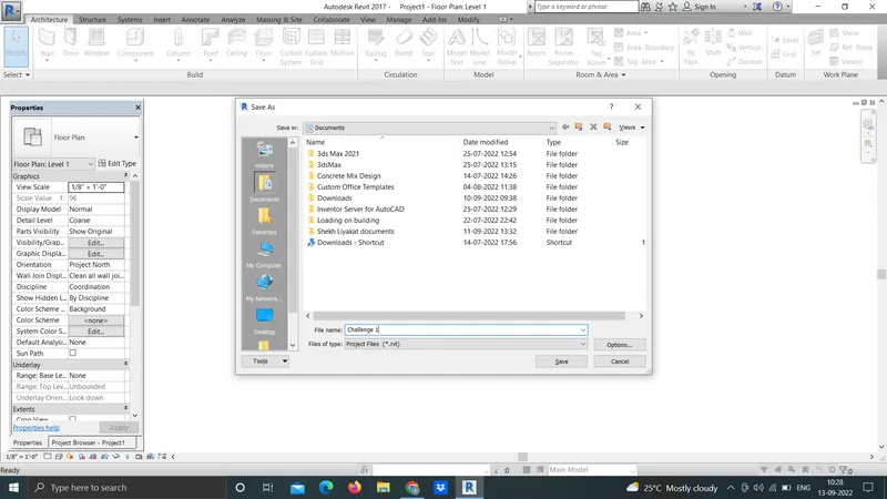
RESULT: I understood how to save revit project file.
2) AIM:
Save the new project file. Close and open using icons from file toolbar.
INTRODUCTION: In this challenge general information about all tools present in revit is discussed and purposes of revit for different work also taken into consideration.
PROCEDURE:
Go to the file menu,click the save option in it.
Give name to the file and click save button.
To change the location of the saved project.Click on save as and enter a different location.
To open a file in the file menu open project.
To close the file>FILE>CLOSE.
The file is saved and opened and closed accordingly.
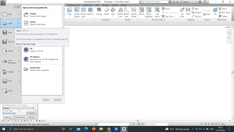
RESULT: I understood how to open, close and save the file using file menu tab in revit software.
3) AIM
From the architecture/ structure toolbar familiarize with options to draw a wall. Create a rectangular layout of walls of about 40’-0” X 35’-0”.
INTRODUCTION: In this challenge general information about all tools present in revit is discussed and purposes of revit for different work also taken into consideration.
PROCEDURE:
Open the revit software.
Select>new>imperial>architectural template.
Select wall from the architectural tab.
Specify a point on the screen and to the right type 40'.
Now to the downwards direction type 35'.
To the left type 40'.
Close the figure.
A rectangle 40' x 35' is created.
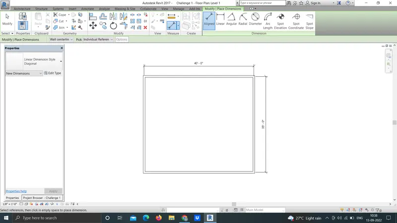
RESULT: I understood how to draw rectangle of walls using wall tools.
4) AIM:
From the Annotate toolbar use the aligned option to add dimensions to the layout.
INTRODUCTION: In this challenge general information about all tools present in revit is discussed and purposes of revit for different work also taken into consideration.
PROCEDURE:
Click on annotate toolbar.
Click on aligned option.
Click on the side of wall and drag to whereever we need to place it to show the dimensions.
Similarly do the same on the other side.
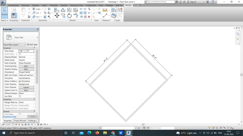
RESULT: I understood how to annoate geometry using annotation tools in revit.
5) AIM
Use the properties browser to switch to different wall types.
INTRODUCTION: In this challenge general information about all tools present in revit is discussed and purposes of revit for different work also taken into consideration.
PROCEDURE:
Select the wall tool in the top of icon then it has many options of wall types like curtain walls,masonary wall,basic wall.
Use wall one by one.
Select the required wall length and width.
Click on the walls and change accordingly.
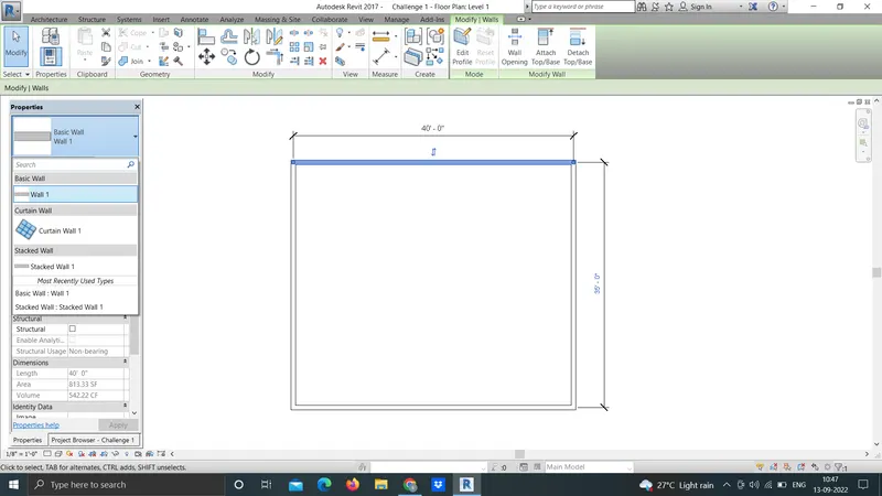
RESULT: I understood how to change properties of elements using properties browser.
6) AIM
Create a 3D view from the view toolbar and save the view with the appropriate name.
INTRODUCTION: In this challenge general information about all tools present in revit is discussed and purposes of revit for different work also taken into consideration.
PROCEDURE:
Press the view bar on the view cube on the right sided of the workspace.
Open the 3D view
Click on the view template and click on create template from current view.
Then the view dialogue box,insert the name as 3d view and click ok.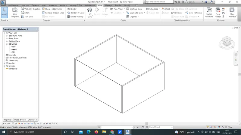
Then view will be created and we can take the view from apply template properly to current view.
RESULT: I understood how to open 3d view and how to save different views in revit software.
7) AIM : Navigate through the 3D model using the view cube. Orbit/pan through the model layout created.
INTRODUCTION: In this challenge general information about all tools present in revit is discussed and purposes of revit for different work also taken into consideration.
PROCEDURE:
Press the view bar on the view cube on the right sided of the workspace.
Click the different views.
To pan click on the navigation wheel below the view cube.
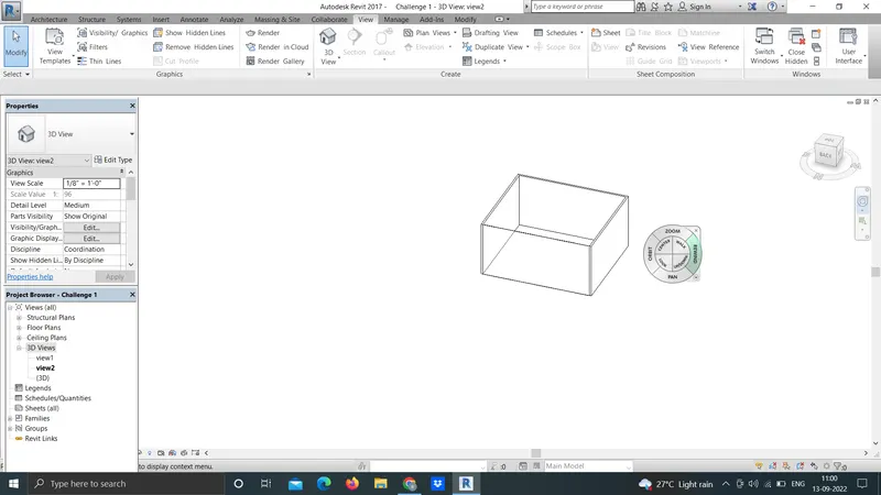
Click on the option to view the navigation view of the view bars.
Click on the left the cursor and move the mouse to pan.
RESULT: I understood how use navigation tool bar for pan, zoom and orbiting the model in revit software.
8) AIM
Use the visibility settings option below to switch model to shaded, realistic, hidden lines options.
INTRODUCTION: In this challenge general information about all tools present in revit is discussed and purposes of revit for different work also taken into consideration.
PROCEDURE:
Click on the cube at the bottom toolbar-visual style.
Select the hidden lines.
Select the model shaded.
Select the realistic view.
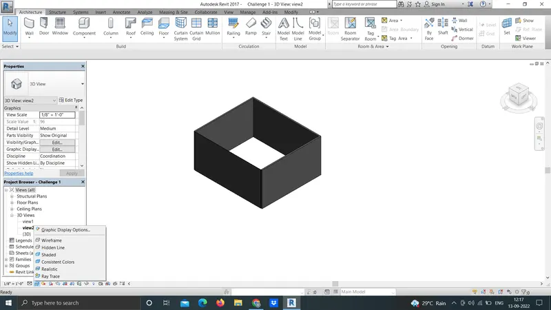
RESULT: I understood how to toggle between differents graphical displays of model in revit software.
9) AIM:
Turn the sun path on and off to view shadings in the layout created.
INTRODUCTION: In this challenge general information about all tools present in revit is discussed and purposes of revit for different work also taken into consideration.
PROCEDURE:
Click on the icon of sun on bottom toolbar.
Click it so that the sun path is on.
Date and time will be visible.
Similarly put the sun path off.
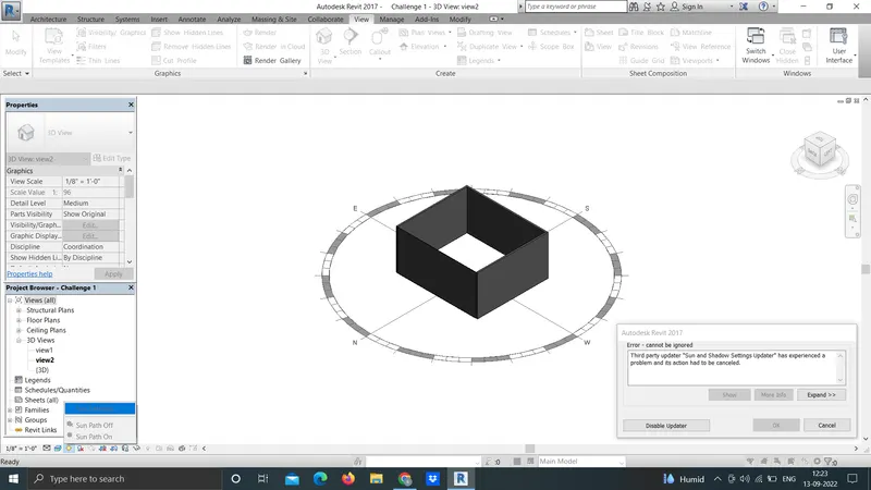
RESULT: I understood how to use sun path setting for building model in revit software.
10) AIM:
Use the Manage toolbar to enter project settings, project name, and project issue date.
INTRODUCTION: In this challenge general information about all tools present in revit is discussed and purposes of revit for different work also taken into consideration.
PROCEDURE
Click the managetoolbar and project information.
Project information dialogue box appears.
From the other click on the project issue date and give a value.
Similarly select the project name , project status , client name, project status, client name, project address and project address and project number.
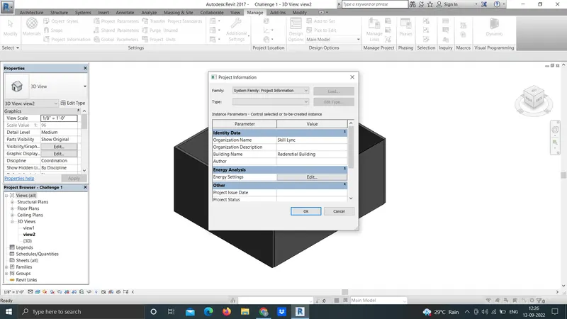
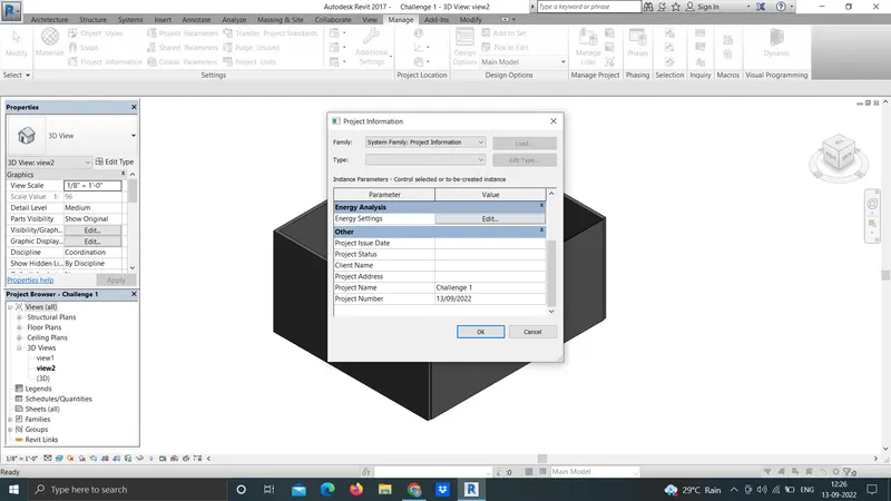
RESULT: I understood, how to fill project information using mange tool in revit software.
11. AIM: ANALYZE toolbar in revit and its benifits in modelling and drafting.
Analyze toolbar in revit helps in evaluating the building performance and analyzing the model by boundary conditions, load bearing etc
It also evaluates the sustainability of the model
Conduct structural analyses and export to analysis and design applications with the analytical model while you create the physical model in Revit.
Benifits of analyze tool in design and modelling
Perform 3D structural analysis. Additionally, extract 2D and 3D subsystems with an automatic load takedown
Check the analytical model in Revit with comprehensive warning dialog and display options for an extended check of the model
Activate advanced calculation options such as construction phases for selfweight
Manage and design reinforced concrete elements according to Eurocodes within Revit (slabs, columns, beams e.g. according to DIN EN 1992)
Structural Analysis Professional is integrated graphic software for modeling, analyzing and designing various types of structures. You can use it to create structures, perform the structural analysis, and verify results
RESULT: I understood benefits of analyse tool in software for drafting and modeling.
12.
AIM: To understand the different links that revit support to be linked to the model.
LINK REVIT
Open an existing model or start a new model.
Link another model into this model.
Click Insert tab Link panel (Link Revit).
In the Import/Link RVT dialog, select the model to link.
To access tools for link management, click Manage tab Manage Project panel (Manage Links).
To update linked models without closing the current project, we can reload the linked models.
Unload linked models to temporarily remove them from the project.
LINK IFC
To use an IFC model as a reference for additional design work, link the IFC file to a Revit model.
Before linking an IFC file, click File tab >Open> (IFC Options) and use the Import IFC Options dialog to do the following:
Select a default Revit template to use for IFC files.
- Load an IFC class mapping file or manually assign Revit categories to IFC classes and types.
- Make sure the IFC file contains the geometric data needed for the Revit capability that you plan to use. For more information,
- Open the Revit model.
- Click Insert tab>Link panel>(Link IFC).
- In the Open IFC File dialog, navigate to the IFC file, select it, and click Open.
LINK CAD
- Open the Revit model.
- If you want the linked file to display only in a particular view, open that view.
- Click Insert tab>Link panel> (Link CAD).
- In the dialog, for Files of type, select the desired file type.
- Navigate to the folder that contains the file to link, and select the file.
- Specify options.
- Click Open.
- If, for Layers, you chose Specify, the Select Layers/Levels to Import/Link dialog lists the layers in the file. Select the desired layers, and click OK.
- Unselected layers are not available in the Revit project. (However, the layers still exist in the CAD file.)
LINK TOPOGRAPHY
Topography provides context for the building model in Revit. If the civil engineer later updates the topography, you can reload the link to see the changes in the Revit model.
MANAGE LINKS
To access tools for link management,
Click Manage tab>Manage Project panel>(Manage Links).
13) Revit provides several different ways to collaborate with team members who are also using the software.
- You can link multiple Revit models together, allowing team members to work in context.
- Through worksharing, users on the same local area network (LAN) can work together in the same Revit model.
- When collaboration needs to occur among users who are not in the same geographic location, use Revit Server or Revit Cloud Worksharing.
- Revit Server connects offices who share a network but are not in the same geographic location.
Revit Cloud Worksharing is a cloud-based service that allows any Revit users inside or outside a network to collaborate on a Revit model.