Introduction to REVIT concepts
- CHALLANGE 1 : INTRODUCTION TO REVIT
- SOFTWARE USED : AUTODESK REVIT 2023
- QUESTION 1
- AIM :
- From the file menu, create a new project (Structural / Architectural / Construction template ) and name the project appropriately
PROCEDURE :
- Double click on revit 2023 software which is alrady download from autodesk website
- revit is open
- it shows the tab like this
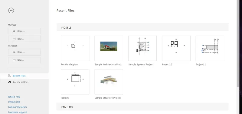
- then click on NEW
- the dialogue box is open
- in this box click on dropdown
- select the templet file as,
- Architectural templet as shown in below
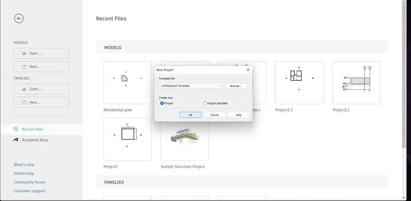
- click OK
- then ,
- go to the file
- click on SAVE
- then dialogbox is open
- select the file name as REVIT CHALLANGE 1
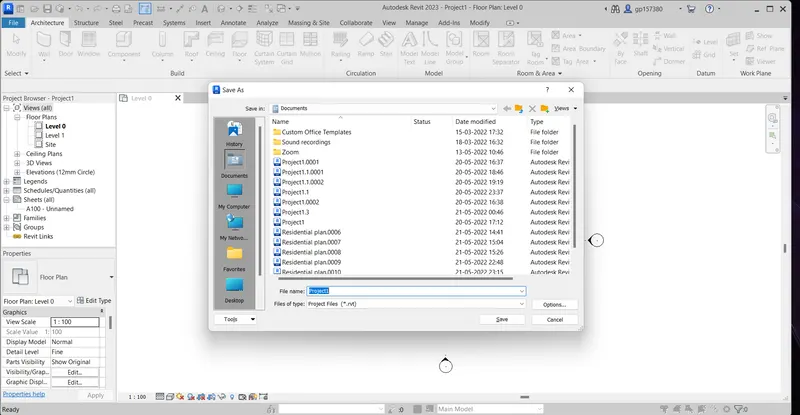
- click on save
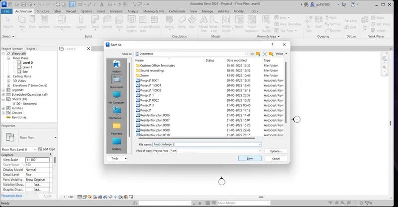
- in this way new file is created .
- RESULTS :
- THE NEW FILE IS CREATED WITH NAME REVIT CHALLANGE 1 .
- QUESTION 2:
- AIM :
- Save the new project file. Close and open using icons from file toolbar
PROCEDURE :
- double click on revit software which is alrady installed in laptop
- after the window is open like this as shown in below
- click on NEW
- then a dialogbox is open
- in this dialogbox click on dropdown
- select the templet file as
- Architectural templet as shown in blelow
- click OK
- then go to the file
- click on save
- the dialogbox is open
- give the file name as REVIT CHALLANGE 1
- then , click on save
- then, save it
- after that click on FILE
- click on open
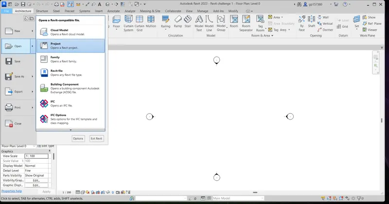
- then click on PROJECT
- the new dialogbox is open there
- as shown below
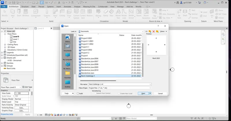
- from this dialogbox select the requried file templet
- and click on OPEN
- in this way saved file is open in revit
- RESULTS :
- THE FILE HAVING NAME AS REVIT CHALLANGE 1 IS SAVED AND THEN OPENED BY USING THE FILE TOOLBAR
- QUESTION : 3
- AIM :
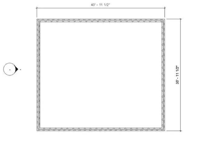
- From the architecture/ structure toolbar familiarize with options to draw a wall. Create a rectangular layout of walls of about 40’-0” X 35’-0”
PROCEDURE :
- click on revit softaware in our laptop
- then revit software is open
- it shows window like this
- click on NEW
- the dialogbox is open there
- in that dialogbox click on dropdown
- select the architectural templet file as shown below
- click on ok
- then click on FILE
- dilogbox is open
- then click on SAVE menu from that dialogbox
- give the file name as REVIT CHALLANGE 1
- and save this file
- then click on wall tab
- then go to the DRAW menu
- select the line option to draw the rectangle
- select the first point anywhere
- move the cursour right < 40'
- then move downward <35'
- then move toward left <40'
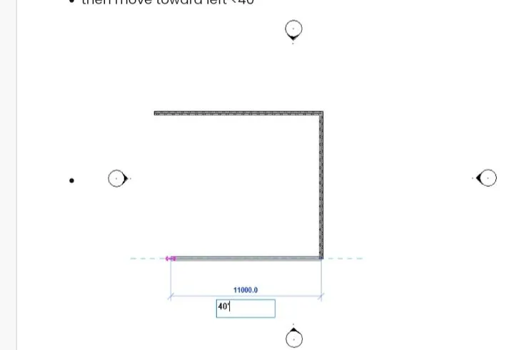
- then join the first point
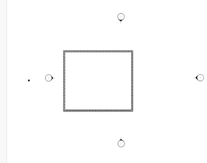
- the wall is ready
- RESULTS :
- IN THIS WAY WALL IS CREATED IN REVIT 2023 SOFTWARE AS SHOWN IN BELOW
- QUESTION : 4
- AIM :
- From the Annotate toolbar use the aligned option to add dimensions to the layout
- PROCEDURE :
- start the revit software in laptop by double clicking on revit software
- then it takes some time to start
- then some tab is opend shown in below
- click on NEW from homepage
- one dialogbox is opened
- from this dialogbox click on dropdown
- and select te architectural templet file
- click on ok
- then click on FILE
- dialogbox is opened
- then give the file name as revit challange 1
- and save the file
- then click on wall option
- then go to the draw menu
- select the line option to draw the wall
- click on anywhere for first point
- move the coursur right side <40'
- then go downward <35'
- then move coursor left side <40'
- then join it at first point
- then type the UN
- project unit dialogbox is open
- then set the units as feet and fractional inches
- click ok
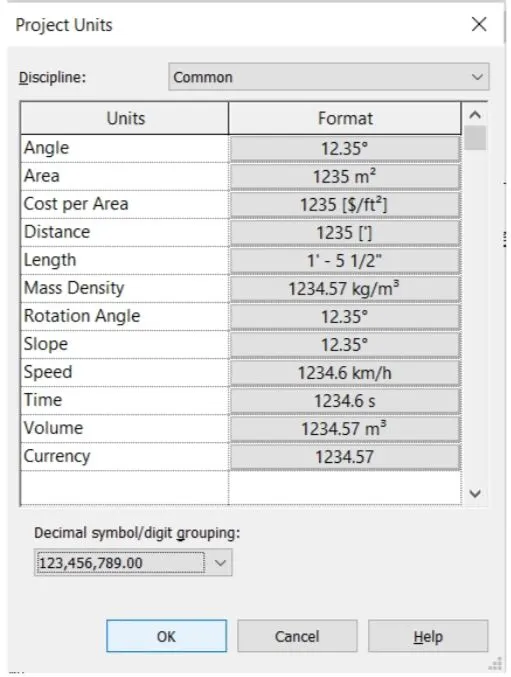
- then go to the anotation tab
- click on liner dimension
- select the first point and endpoint
- and give the dimension
- then walls are ready with dimension
- RESULTS :
- THE WALLS PLAN IS READY WITH DIMENSION
- QUESTION : 5
- AIM :
- Use the properties browser to switch to different wall types
- PROCEDURE :
- start the revit software in our laptop
- it take some time
- after that it shows tab shown in below
- click on NEW from home page
- the a dialogbox is opened
- from this click on dropdown
- select the templet file as
- architectural templet as shown below
- click ok
- then save the templet file
- for this go to the FILE menu
- click on SAVE
- the dialogbox is opened
- give the file name as revit challange 1 as shown below
- and save it
- then type UN for project units
- select the project units as foot and inches
- then draw the wall for this ,
- click on wall
- select the first point anywhere
- then move the coursor toward right <40'
- then downward <35'
- then move the cousor left <40'
- then joint the first point
- in this way wall is created
- if properties tab is not availlabe then type PP for this
- and for project browser right click
- go to the browser select the project browser
- select the wall component
- go to the properties
- and change the wall type as wall-Ret_300Con as shown below
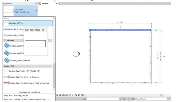
- do same thing to the all component
- RESULTS :
- BY USING PROPERTIES BROWSER SWITCHING THE WALL TYPE IS READY AS SHOWN BELOW
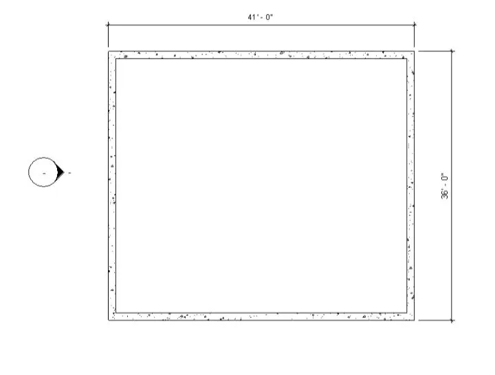
- QUESTION : 6
- AIM :
- Create a 3D view from the view toolbar and save the view with the appropriate name
- PROCEDURE :
- start the revit 2023 software which is alrady installed in our laptop
- it takes some time to start
- after that it shown the homepage shown in below
- click on NEW from homepage
- then dialogbox is opened
- select the templet file as architecural templet
- then save this file for this
- click on file
- dialogbox is opend
- from this click on SAVE
- and save this file name as revit challange 1
- click on save
- then type UN for project units
- and change the project unit as foot and fractional inches
- click ok
- then click on wall
- select the first point
- move the cursor toward right <40'
- then move downward <35'
- then move left direction <40'
- then join the first point
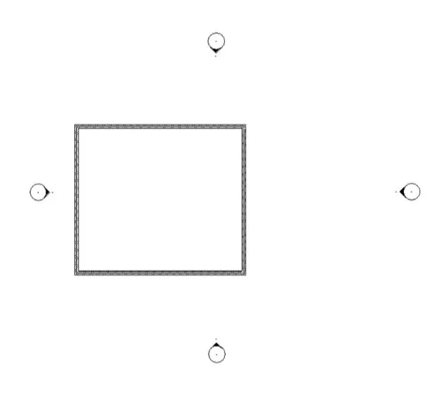
- then go to the annotation tab
- clcik on linear dimension
- and give the proper dimension to the walls plan
- go to the top most part of revit software
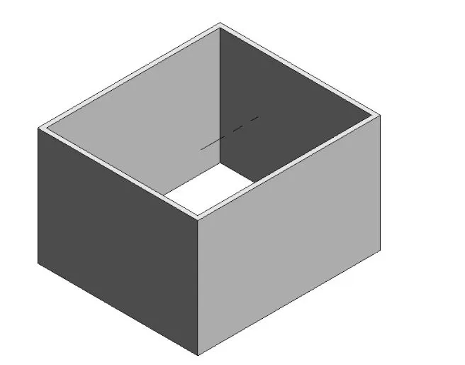
- click on DETAULT 3D VIEW
- click on this
- the 3d view is created shown in below
- then from the view cube
- right click on view cube
- click on save view
- give the view name as view1
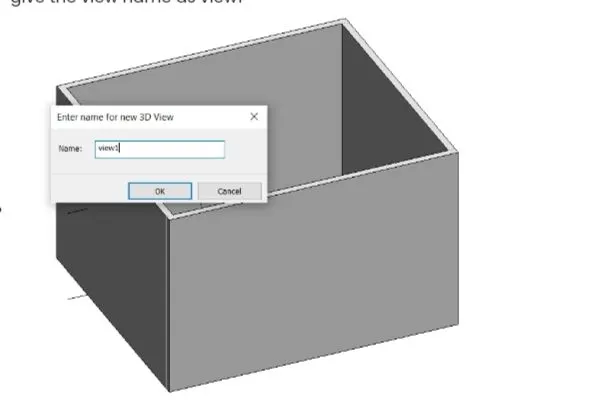
- click ok
- RESULTS :
- IN THIS WAY 3D VIEW IS CREATED AND SAVE THE VIEW AS VIEW NAME IS VIEW1.
- QUESTION : 7
- AIM :
- Navigate through the 3D model using the view cube. Orbit/pan through the model layout created
- PROCEDURE :
- STEP 1:
- start the revit 2023 software which is alrady installed from autodesk website
- it takes some time to start
- then homepage of revit software is opened as shown below
- from this home page
- click on NEW
- then one dialogbox is open
- click on dropdown
- select the templet file as architectural templet as shown below
- click ok
- go to the FILE
- one dialogbox is open
- from that dropdown
- click on save
- give the file name as revit challange 1
- click on save
- change the project units by command un
- change the units as foot and fractional inches
- click on ok
- click on WALL
- select the firstpoint anywhere
- then move the cursour toward right side <40'
- then move downward <35'
- then move leftside <40'
- then join the first point
- then go to the annotation tab
- click on linnear dimension
- and give the dimension to the wall
- go to the topmost part of revit software
- click on DEFAULT 3D VIEW
- then 3d view is created
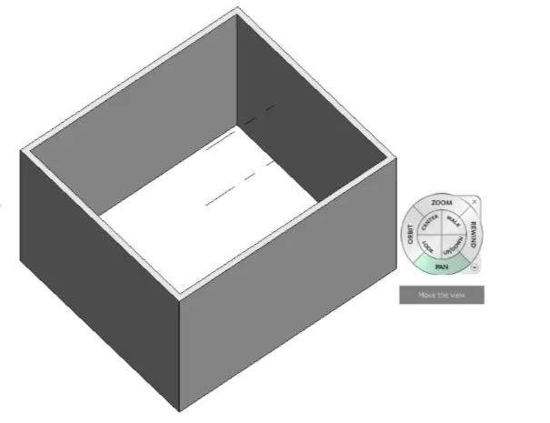
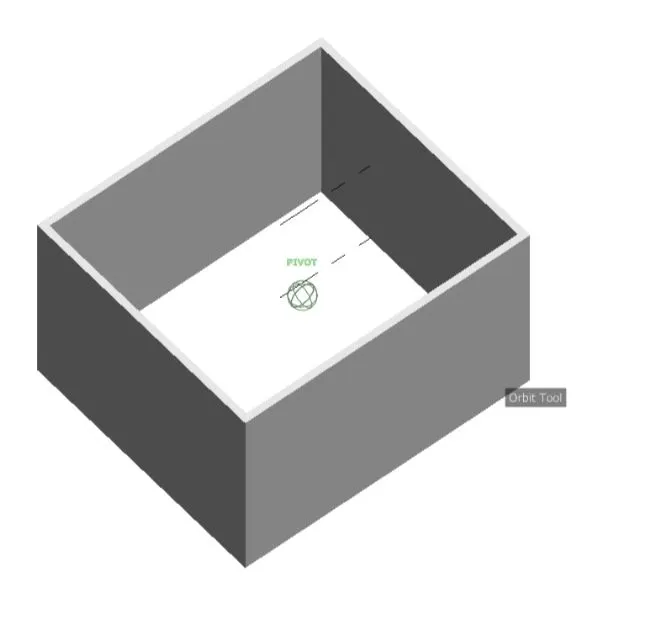
- then click on view tab
- go to the user interface
- select the nevigate tab
- view cube is apper
- then right click to the face of view cube
- and save the view as view1
- click on save
- click on nevigation wheel shown in fig
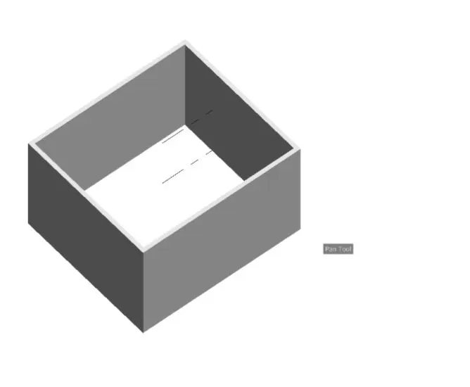
- and use the orbit and pan option to the object shown in results
- RESULTS :
- FIRST DRAW THE WALL 40'X35' . CREATE A 3D VIEW OF IT AND FROM NAVIGATION WHEEL USED THE ORBIT AND PAN OPTION .
- QUESTION : 8
- AIM :
- Use the visibility settings option below to switch model to shaded, realistic, hidden lines options
- PROCEDURE :
- start the revit 2023 software which is alrady installed from autodesk website
- it takes some time to start
- after that home page is open as show below
- click on NEW tab from homepage
- one dialogbox is open
- in that dialogbox click on dropdown
- select the templete file as architectural templet file as shown below
- click on OK
- then save this file
- click on file
- one dialogbox is open
- give the file name as revit challange 1
- and then save it
- click on save
- then type UN for change the project units as foot and fractional inches
- then click on wall option
- clcik anywhere for first point
- move the cursour toward right side <40'
- move downward <35'
- then move toward left side <40'
- then click on first point
- the walls are ready as shown below
- then click on annotation tab
- select the linnear dimension
- and give the dimension to the section
- then go to the top section of revit software
- click on DEFAULT 3d view
- then 3d view of plan is created as shown below
- right click on face of view cube
- and save the view
- give the name of view is view1
- click on ok
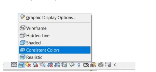
- click on visual style option
- one dialogbox is open as shown below
- and select the requried view
- some view is created shown in results
- RESULTS :
- CREATE THE PLANS DIMENSION AS 40'X35' THEN 3D VIEWS ARE CREATED AS SHOWN BELOW
- REALISTIC VIEW :
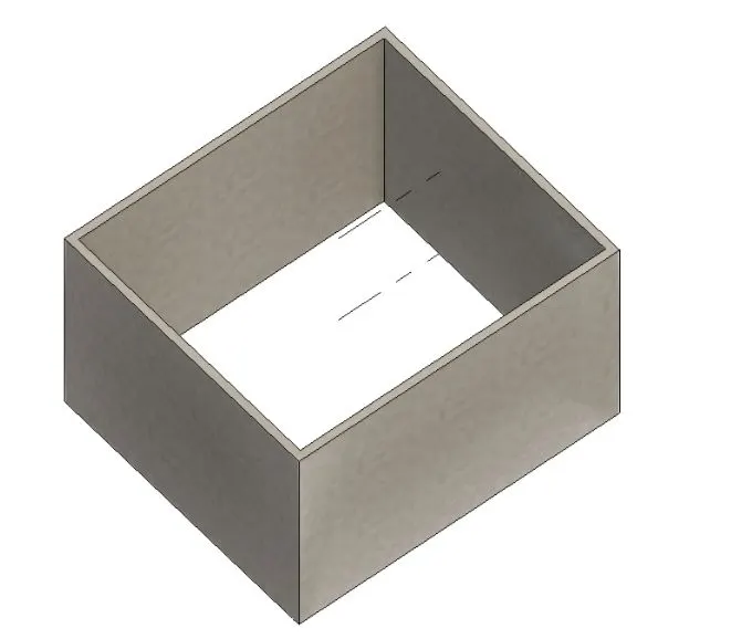
- SHADED VIEW :
- HIDDEN VIEW :
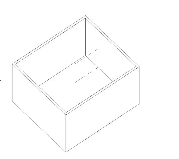
- QUESTION : 9
- AIM :
- Turn the sun path on and off to view shadings in the layout created
- PROCEDURE :
- start the revit 2023 software which is alrady installed from autodesk website
- it takes some time to start
- after that some home page is display shown in below
- click on new from homepage
- one dialogbox is open
- from that dialog box select the file templet as architectural file templet
- as shown below
- click ok
- then save the file
- click on file from menu
- one dialogbox is open
- then give the file name as
- revit challange 1
- and save the file
- after that change the project units as
- foot and fractional inches
- click ok
- then click on wall option
- select the first point anywhere
- move the cursour right <40'
- then move downward <35'
- then move to left side <40'
- then join the first point
- the wall structure is ready
- then go to the annotation tab
- select the linnear dimension
- and give the dimension to the structure
- then go to the topmost part of revit software
- click on DEFAULT 3D VIEW
- then 3d structure is ready
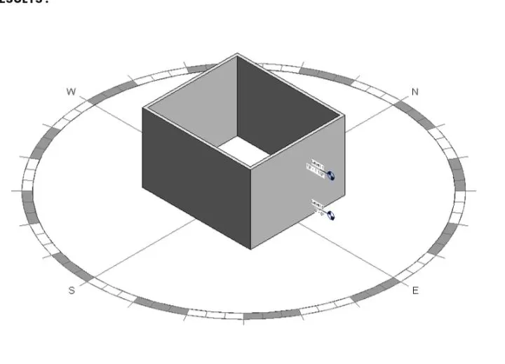
- then click on sunpath option which is at bottem of the software
- click on sunpath on
- RESULTS :
- QUESTION : 10
- AIM :
- Use the Manage toolbar to enter project settings, project name, and project issue date (choose according to your convenience)
- PROCEDURE :
- double click on revit software to start
- it takes some time to start
- after that homepage is opened
- as shown below
- then click on NEW option from homepage
- one dialogbox is open
- in that dialogbox click on dropdown
- select the tamplet file as archituctural templet
- as shown below
- click on file
- then click on save
- give the file name as revit challange 1
- shown in below
- click on save
- then type un for project units
- select the length units as feet and frictional inches
- click on ok
- then draw the walls
- for that click on walls
- select the firstpoint anywhere
- move the cousour right side <40'
- then move the cousour downward <35'
- then move the coursour leftside <40'
- and then join the first point
- wall plan is ready
- then go to the annotation tab
- select the linner dimension
- and give the dimension to the plan
- then at a top of revit default 3d view option is availlable
- then click on that option
- 3d view of rectangular walls is created
- then go to the manage tab
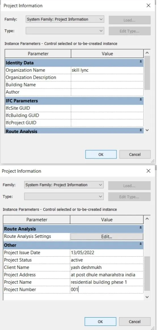
- click on project information
- one dialogbox is open shown in results
- RESULTS :
- QUESTION : 11
- AIM :
- What is the Analyze toolbar used in Revit? How it is beneficial for design and modeling
- ANS :
- analyze tab shown in below

- in this tab contains tools which is used to adjust the analytical model, check for consistency, reset the module and check the member suport in this tab .
- from this tab we can added the boundary conditionsand types of loads
- from this aalyze tab we can edit the load cases
- this toobars is used to create the saperators
- we can also load combinations
- the reports like heating ,and colling load report, panal report etc are prepared from this tab
- from this tab we can undestand how sustainable and energy efficient the building is .
- the distance and time travell from one end to another end can be calcuated from this tab
- it is used to helps to perform energy optimisation and energy analysis
- we can achive the progress of project together from all disciplines
this is about analyze tab in revit 2023 software .
- QUESTION : 12
- AIM :
- What are the links that Revit supports to be linked to the model?
- ANS :
- about link explain in below :
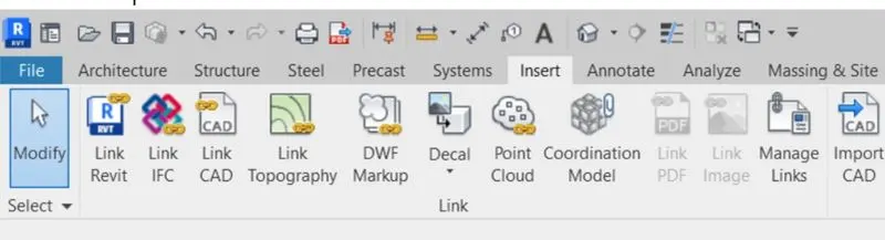
- from the insert tab we can get the links LINK REVIT :
- it allows to link another revit module to the current module
- LINK IFC :
- it allow to link another IFC file as a referance where we want to perform additional design work in revit
- LINK CAD :
- it allow to link the CAD file. to create 3D using revit , we can link the CAD file 2D drawing
- LINK TOPOGRAPHY :
- it allows to link the existing topography to the current module
this is all bout linkes in revit software .
- QUESTION : 13
- AIM :
- Why do you need the Collaborate tab in Revit? How it supports modeling and its efficiency
- ANS :
- about the collabration tab explen below :

- it is the one of the feacture in wich it helps the tema member to work on a single module simeltinously .
- we can link mutiple revit module together allowing tema member to work in context
- when the collabration need to occer amoung users who are not in same geographic location , then we can use revit server or revit cloud work shairing
- the efficiency of the modelling will be high as the work can be finished faster
- due to collabration tab we do not wait for one module to be complete to start the module of the next work
- for example : if a electrial and structural enginners wants to in a module simultionusly the collabration option create the central file and we will have to facilites to create the multiple files that enables collabration .
this is about collabration tab in revit .