Introduction to REVIT concepts
CHALLENGE WEEK - 1
REVIT
Question no.1: From the file menu, create a new project (Structural / Architectural / Construction template ) and name the project appropriately
- Aim:
- To create a new project.
- To name the project appropriately.
- Procedure:
- To create a project template.
- After opening the revit software we will have a display thea contains many options.
- In that there will be a option called New.
- The display is shown below
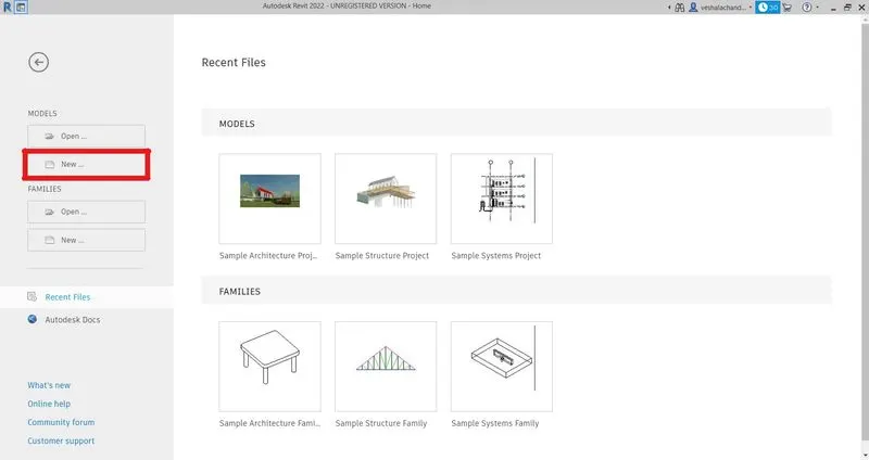
- Open the new tab to enter the next step in creating the file.
- After opening the new tab we need to select the required template that are set default in the software.
- The template to be chosen is based on the type of project we are to work with.
- And the template contains the particular specifications required for the project.
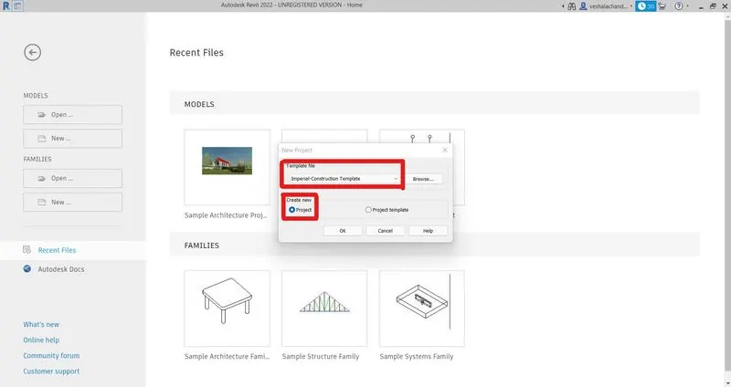
- This selecting the required project template can alos be done using the file droop down panel in the workplane of the revit.
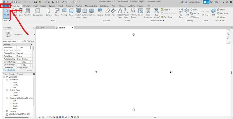
- After selecting the drop down panel in file .
- We need to choose the new option.
- After which you will see the steps which is said initially.
- After this You need to name the project.
- Hence just the File drop down panel.
- In this you will see the save as option .
- Then You need to enter in "save as" option ann select the "project' tab.
- Then you will have a interface as shown below
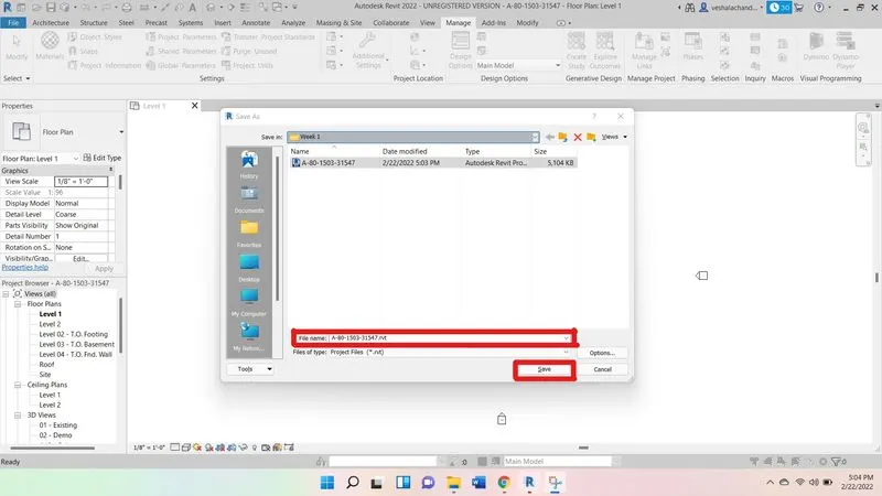
- Then you can name your project as you desire.
- And can save it to your desired foldres in your computer.
- Result:
- Thus we have created the project file with proper template.
- We have named the project appropriately.
- All the procedure steps were attached step by step.
Question no.2: Save the new project file. Close and open using icons from file toolbar
- Aim:
- To save the created project file.
- To use file toolbar to close and open the project file.
- Procedure:
- The created project file is set in the working display.
- Now to save the project file.
- Go to the "file" in the toolbar.
- Open the drop down panel and save the file.
- In that there will be a option called New.
- The display is shown below
- Or the saving can be done by the other easy access method.
- The step is shown below
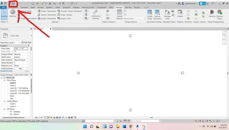
- Thus the file which was created is successfully saved
- Noe to close and open using teh file toolbar.
- Select the file drop down panel.
- Choose the close option in the bottom of the panel.
- Then to open same using the drop panel choos open tab.
- And then choose the required file to open.
- Result:
- Thus we have save the created project file.
- All the procedure steps were attached step by step.
Question no.3: From the architecture/ structure toolbar familiarize with options to draw a wall. Create a rectangular layout of walls of about 40’-0” X 35’-0”
- Aim:
- To create a rectangular layout of wall.
- To familiarize with the wall option.
- Procedure:
- To create the required layout.
- We need to choose the architecture tab or the structrual tab in the tool tab.
- The procedure is shown below
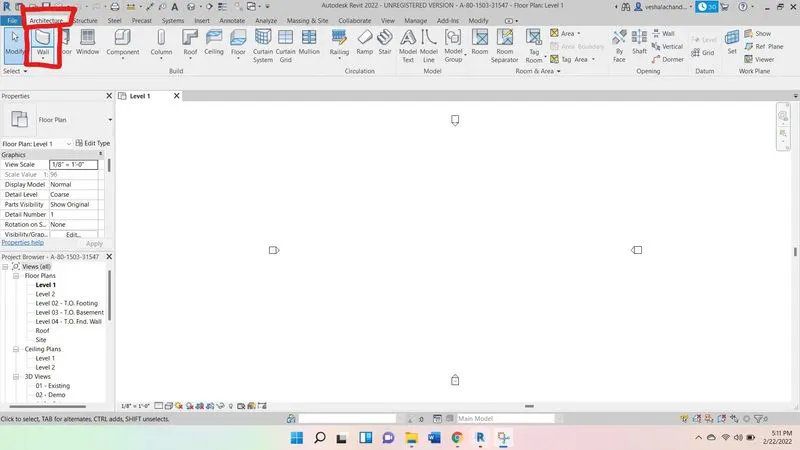
- Then the wall of required size is chosen.
- And then the required layout with the specified dimesions is drawn.
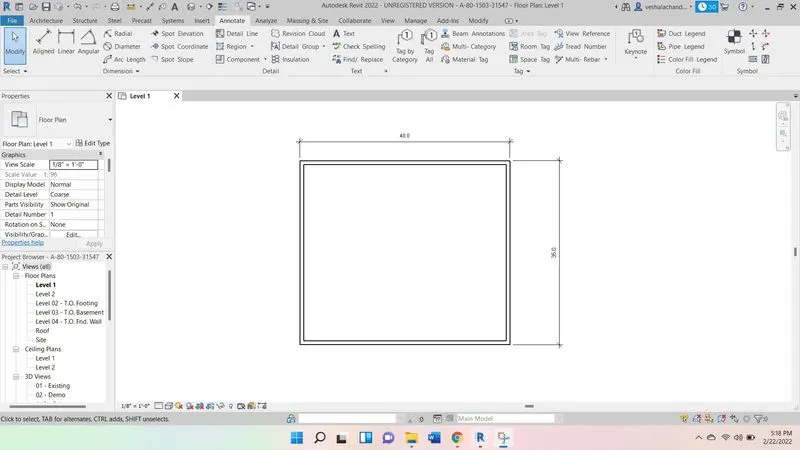
- Then to know more about the walls.
- Open the dropdown panel of the wall and browse teh wall types.
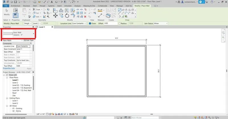
- And different type of walls were used .
- Result:
- Thus we have created the required layout of the wall.
- All the procedure steps were attached step by step.
Question no. 4: From the Annotate toolbar use the aligned option to add dimensions to the layout
- Aim:
- To use the annotate toolbar .
- To add dimesions to the created layout
- Procedure:
- After creating the layout.
- Go to the annotate tool tools panel.
- Choose the annotate tool.
- And then choose the aligned option to measure the distance of the layout.
- Thus measured dimesion is shown below.
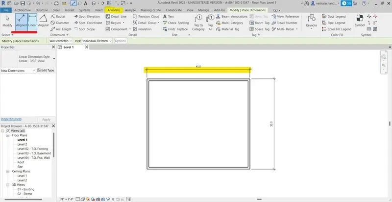
- Thus the measurement for the layout is odne using the annotation.
- Result:
- Thus the measurement for the layout is odne using the annotation.
- All the procedure steps were attached step by step.
Question no. 5: Use the properties browser to switch to different wall types
- Aim:
- To use the properties toolbar.
- To swith over different type of wall types.
- Procedure:
- To view the different wall types.
- Initially go the architectural tab.
- Then choose the wall tab.
- Abter choosing the wall we can see a wall type openend in the modify tab in the properties tab.
- Then open the dropdown tab.
- And then we can explore over all the types of the walls from that properties tab.
- Thus the snaip of the procedure is shown above.
- Result:
- Thus the properties tab was used to surfd over the type of walls.
- All the procedure steps were attached step by step.
Question no. 6: Create a 3D view from the view toolbar and save the view with the appropriate name
- Aim:
- To create a 3d view from toolbar.
- To save the selected view with appropriate name.
- Procedure:
- To create the 3d view.
- Initially we need to go to the 3d tab.
- So choose the 3d view entry from the toolbar.
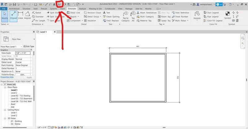
- Then the 3dview will be available to view.
- Then viewcube present on the right corner can be used to surf or orbit over the 3d views.
- Then the corner of the viewcube is selected to save the view.
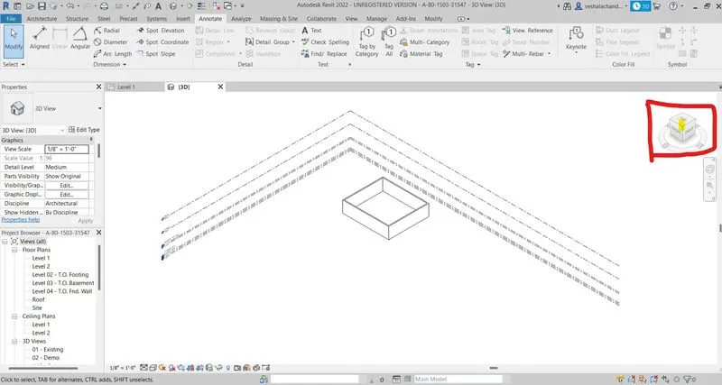
- The process is shown above.
- The view saving is shown below
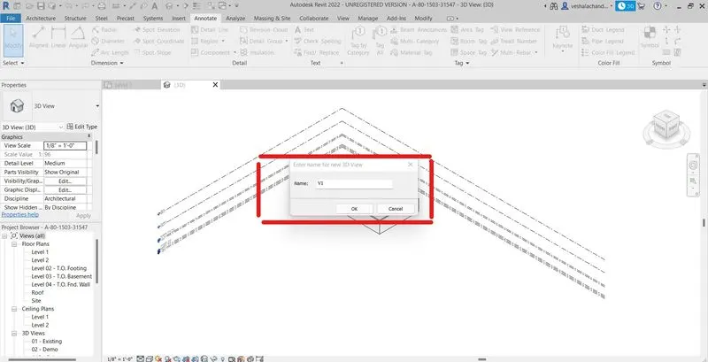
- Thus the view is browsed and required view is saved.
- Result:
- Thus the 3d view is browsed .
- The required view is saved
- The procedure is saved.
Question no. 7: Navigate through the 3D model using the view cube. Orbit/pan through the model layout created
- Aim:
- To navigate through the 3d model using view cube.
- To Orbit/pan through the model layout created.
- Procedure:
- To create the 3d view.
- And use the 3d viewcube to orbit/pan throught the model layout.
- Then the view can be saved as per the requirement.
- The part of the procedure is shown above.
- Result:
- Thus the 3d view is browsed .
- The 3d view is orbit/panned to view the 3d view
Question no. 8: Use the visibility settings option below to switch model to shaded, realistic, hidden lines options.
- Aim:
- To use visibility settings to switch model to shaded, realistic, hidden lines
- Procedure:
- After setting the created model on the display of the workspace.
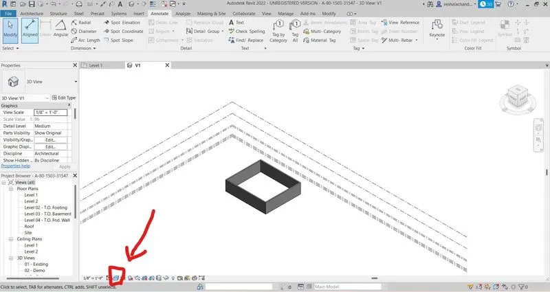
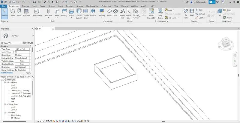
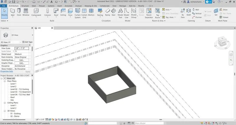
- Move the cursure to the visibility setting present in the bottom the workspace interface.
- Then select the visibilitys etting logo and change the model to required visibilities
- The below image shows the shaded view of the model.
- The below image show the hidden line view of the model.
- The below image shows the relaistic view of the model.
- Result:
- Thus the visibility settings were changed and browsed
- All the browsed visibilities are places above as step procedure.
Question no. 9: Turn the sun path on and off to view shadings in the layout created
- Aim:
- To turn the sun path on and off to view the shading in the created layout.
- Procedure:
- After setting the created model on the display of the workspace.
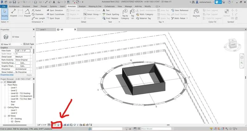
- There is a option in the revit to view the shades created by the sun.
- To see the sun path and the shades.
- There is a tab in the bottom of the workspace.
- Select and set the sun path on.
- And also set the shadows on in the tabs.
- Thus created view is shown below.
- Result:
- Thus the visibility of the sun path and the shadows are shown
- Thus set view is shown in the image.
Question no. 10: Use the Manage toolbar to enter project settings, project name, and project issue date (choose according to your convenience).
- Aim:
- To use manage tool bar.
- To set the project setting, project name and project issue date.
- Procedure:
- After setting the created model on the display of the workspace.
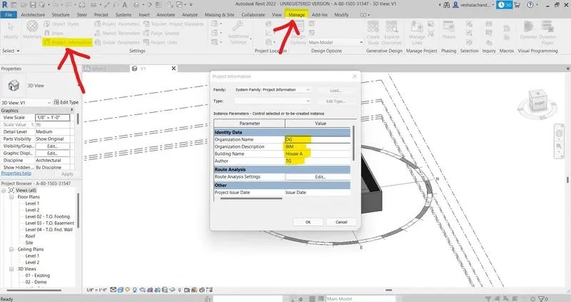
- Select the manage tab in the toolbar.
- Then there is a project parameter tab.
- Choose the tab.
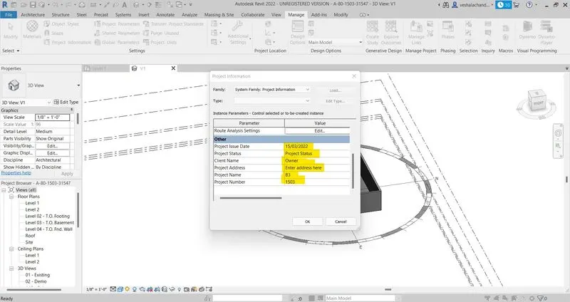
- Then the change the project name , project settings, and project issue date.
- Thus changed setting is shown below
- Result:
- Thus the maange tool bar was browsed.
- Project parameters were set and changed.
- Thus changed parameters is shown above.
Question no. 11: What is the Analyze toolbar used in Revit? How it is beneficial for design and modeling.
- Aim:
- To explain about the analyze toolbar used in revit.
- To list the benefits for design and modeling.
- Procedure:
- The analyze tool bar in Revit is a very important toOL.
- The Analysis Toolkit for Revit software is a suite of tools.
- These tools supports the Building Information Modeling (BIM) process
- And allows us to analyze and check your model from within the Revit environment.
- This tools plays a vital role is designing a model.
- It helps in many major ways such as checking the model
- That the model follows the given boundry conditions.
- And checks weather proper model is created with acceptable standars that is required.
- It is very much benificial in design and modelling.
- As said before in design it analyze the loads that the model contains.
- And proper flow of components when set in sequence which can be more commonly seen in Revit MEP designs.
- When modelling it helps in analyzing the area boundries, Overlapping of elements and etc.,
- Result:
- Thus the analyze tool bar in Revit software was explained.
- Its benefits were listed.
Question no. 12: What are the links that Revit supports to be linked to the model?
- Aim:
- To explain the links can be used in model
- Procedure:
- The links in Revit is link models created.
- Or to be simple, the models can be linked from separate models.
- The models in different inetrface such as Autocadd, Revit MEP or structure.
- These can be linked or made as reference in the main model to be created.
- The links can be linked are seen in the insert tab in the revit interface.
- Result:
- The links taht revit supports were explained.
Question no. 13: Why do you need the Collaborate tab in Revit? How it supports modeling and its efficiency
- Aim:
- To explain the need of collaborate tab in revit
- Procedure:
- Use Collaboration for revit to edit models
- And use Communicator to share your changes with the project team.
- It also helps in connect with other team members using Communicator for Revit.
- And to Check the status and manage your models.
- It supports the model very efficiently to keep a complete check on teh model.
- To create new ideas and share that on the model created .
- You can link multiple Revit models together, allowing team members to work in context
- Through worksharing, users on the same local area network (LAN) can work together in the same Revit model.
- Revit Server connects offices who share a network but are not in the same geographic location.
- By this way collaboration is much more useful
- Result:
- The collaboration tab in revit is explained.