Introduction to REVIT concepts
AIM 1:
To create a new project and name it appropriately
INTRODUCTION:
The product illustrates the creation of a new project file in Revit an naming the project file.
PROCEDURE:
STEP 1:
- Go to START MENU, click on Revit 2021.
- In the Rivet Home page click on new under the models option.
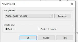
- In the New project dailog box,select the desired templete from the drop-down list
- Crete nwe>project
- Click ok
STEP 2:
- Next click on the file tab.
- Click on save oprion
- Specify the location where you want to save the file
- Enter file name:Arch_drawing1
- Click on save
RESULT:
AIM 2:
To close and open the newly created file using icons from file toolbar.
INTRODUCTION:
The procedure illustrates how to create a file using icons on the file toolbar
PROCEDURE:
- Afre saving the new project file ;Arch_drawing1'.
- Click on the file tab.
- Next click on the close option.
- The file will be closed
- Again go to the Revit Home page.
- Next click on the File tab
- Click on small arrow beside the Open option
- Click on project/Revit file
- The open dailog box appears
- Select the file to be opened
- Click on Open.
RESULT: The project file was successfully closed and opened using te icons on the file toolbar.
AIM 3:
To create a rectangular layout of walls of about 40'0''x35'0''.
INTRODUCTION:
The wall is created with the Architechural wall tool and the detailed procedure is explained with diagrams of each in final result given.
PROCEDURE:
- Go to START MENU,click on Revit 2021
- In the Revit home page click on open under the models option
- Open the previously created project file 'Arch_drawing1.
- As the imperial-Architectural template was selected creating the file the units of the project the by default set to feet-inches
- Select the wall tool by going to Arcitecture>wall>Architectural.
- Specify location linee>finish face:Exterior.
- Click at the desired start point for the wall.
- Move the cursor towards the right hand side of the screen and enter 40'.
- Then move the cursor downwards and enter 35'.
- With the help of tracking ,complete the remaining sides of the wall.
- press esc.
RESULT:
The architectural wall is created.
AIM 4:
From the Annotate toolbar use the aligned option to add dimensions to the layout
PROCEFURE:
Click on the annotate tan and select the aligend dimrnsion
Select the center to center line from the bot side and repeate the process on the another side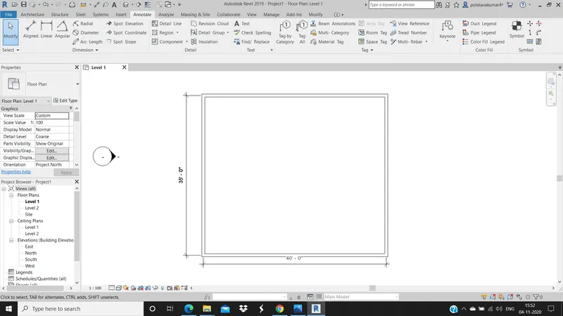
AIM 5:
Use the proprties browser to switch to diffrent wall types
PROCEDURE:
Select the close wall drawn and at the left side properties tab, from the drop down list select thw wall
AIM 6:
Create a 3D view from the toolbar and save the view with the appropriate name
PROCEDURE:
In the viw toolbar simply click 3D and in the visual style realistic
AIM 7:
Navigate through the 3D model using the view cube,Orbit/pan through the model layout created.
PROCEDURE:
In the view toolbat simply click 3D and in the visual style realistic
Use the view cube to change to any isometric view as shown.Also by clicking and moving the mouse key at view cube we can pivot atany way possible.
By clicking on the orbit tool we can easily pivo in any direction or view which we need.
By clicking on the pan view we will be able to move the model up,down,right,left in any direction
AIM 8:
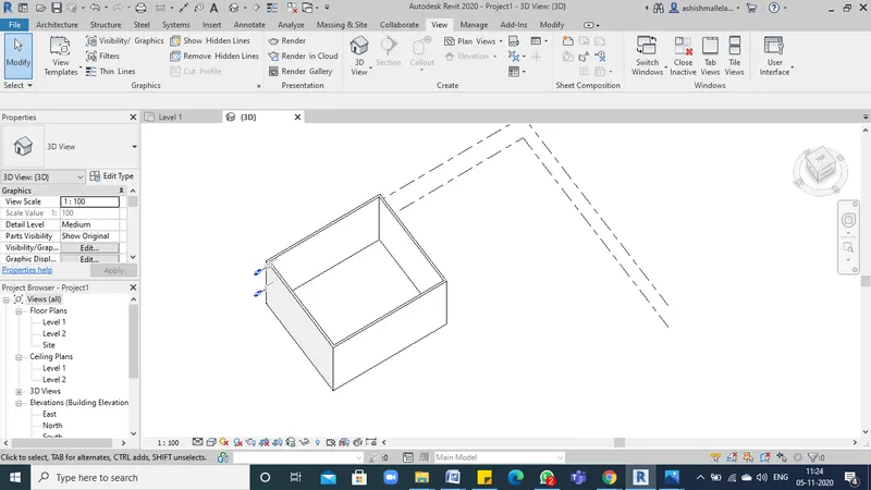
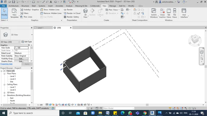
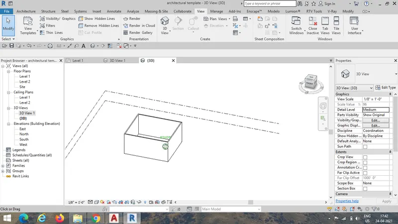
Use the visibility settings option below model to shaded,realistic,hidden lines options
AIM 9:
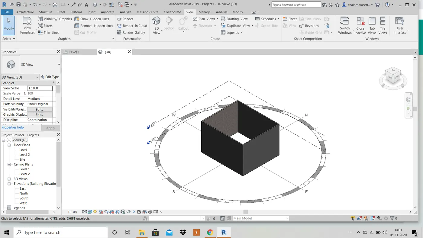
Turn the sun path on and off to view shadings in the layout created
PROCUDURE:
Click on the sun path at the bottem toolbar.
Size of sun path can be changed with respect to the model path.
Date and time settings can also be adjusted as per our requirement
AIM 10:
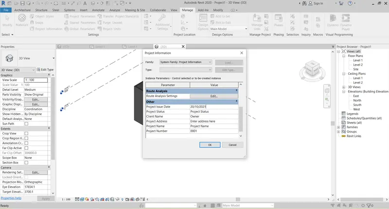
Use the manage toolbar to enter project settings,project name,and project issue date(chose according to your convenience).
PROCEDURE:
In the modify panel click on the project information option to open the project information dialogue box
The project name,issue date and settings was applied as shown
AIM 11:
Analyze toolbar used in Revit and benificial for desing and modeling
PROCEDURE:
Analyse toolbar containg tool that are used to adjust the analytical model,to check for consistency,rest the model and to check member supports in this tab
The toolbar is usedto create the separators
We can add the boundary conditions and type of loads
We can edit the load cases.We can add the load combinations
Mnany types of reports such as heating and cooling load reports, panel reports etc,are prepanel
Distance and time of travel from one end to another end be calculated
We can understand,how sustainedble and energy efficient a particular building is
It also helps to preform energy optimisastion and energy analysis
AIM 12:
Create the links that Revit supports to be linked to the model
PROCEDURE:
Link Revit- used to link anoother Revit model to the current model.
Link IFC- used to link IFC file as refernce, when we want to perform additional design work in Revit.
Link CAD - used to link the CAD file to create 3D using Recit we can link the cad file having 2D drawing.
Link Topgraphy- Used to link the existing topography to the current model
AIM 13:
Collaborate tab in Revit and supports modeling and its efficiency
PROCEDURE:
Collaboration allows team momber to work in a model simultaeously
It supports in communication between the files or drawings
It helps to have the wotk share among the team members
It saves a selecte Backup version to the current working model and rools back changes made to work shaded project.