Introduction to REVIT concepts
INTRODUCTION TO RIVET
1. Creation of new project
Aim : Steps to create a new project in Rivet software and name it.
Procedure:
- Step 1:Open Rivet software
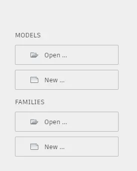
- Step 2:From the model tab ,click on new .
-
- Step 3: A new project dialogue box appears, click on metric- architectural template.
-
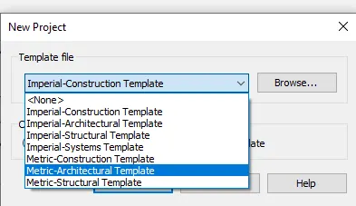
- Step 4: Click on ok.
- Step5: New workspace will be loaded.
- Step 6: To name the project, go to file menu, save and enter the project name as Project 2.
-

 it will be displayed above.
Result: New file with name project 2 is created.
2. To save the file, open and close
Aim : To save a project in Rivet software and close and open using file toolbar
Procedure:
- Step 1: Go to file menu, click on save option .
-
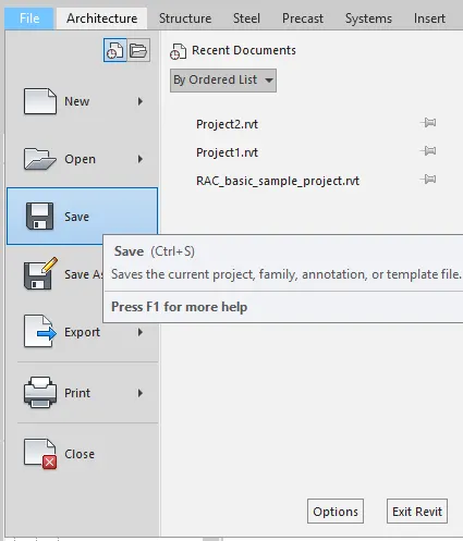
- Dialouge box appears , give the name and click on save.
- To change the location of the saved project ,click on save as and enter a different location.
- Step 2: To open a file, in the file menu click on open, project.
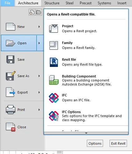
- Open dialogue box appears, click on the required file .
- Step 3: To close the file, in the filemenu click on close.
-
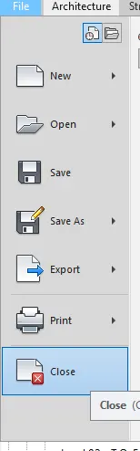
Result: The file is saved and opened and closed by file menu.
3. To draw a wall in Rivet
Aim: To draw a wall in Rivet software by using wall menu in architecture.
Procedure:
- Step 1: Open the rivet software ,select new and select imperial- architecture template.
- Step 2: Clickon wall from the architectural tab - basic wall 8"
- Step 3: Click on the floor plan area and enter 40'
-
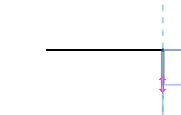
- Step 4:Move the mouse downwards and type 35' .
- Step 5:Again type 40' placing the mouse to left.
- Step 6:Again type 35' upwards
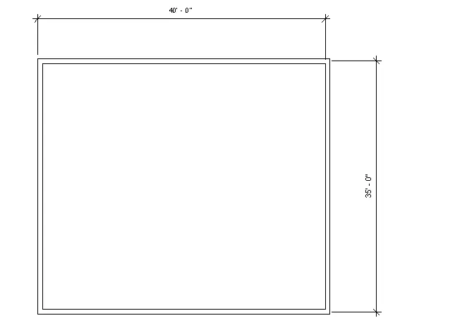
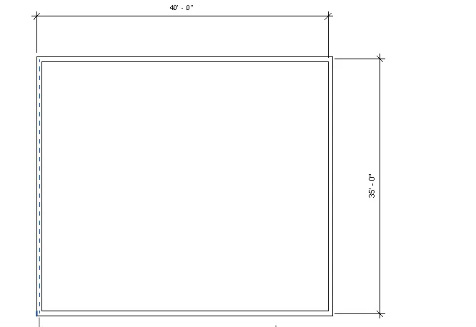
- Step 7: A rectangle is craeted of 40' x35'.
Result: Wall of 40' x35' is created using wall tool.
4. Usage of annottae toolbar
Aim : To use annotate toolbar, annotate option for dimensioning.
Procedure:
- Step 1: Click on annotate toolbar.
- Step 2: Click on aligned option
-
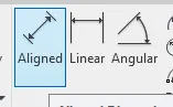
- Step 3: Click on the side of wall where to start then drag the dimension line to where we need .
-
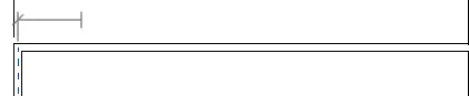
- Similarly do the same on the other side
Result: The dimensions are done using annotate toolbar using aligned option.
5. Use of property browser
Aim : To use property browser to change the type of wall.
Procedure:
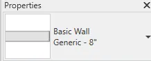
- Step 1: Select the wall , hen in left in the property browser, the property of wall will be displayed.
- Step 2: Click on the drop down menu , we can see different types of wall.
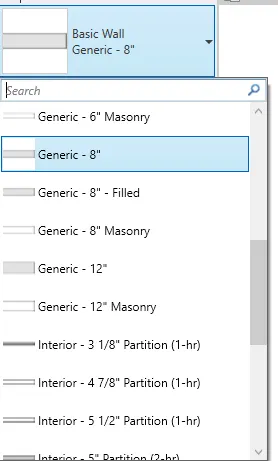
- There are basic walls, curtain walls and stacked walls.
- Step 3: Select the required type , here select 12" masonry, then the selected wall will change accordingly.
Result: With the use of property browser , the wall type are changed .

Basic wall -12"masonry
curtain wall

Stacked wall exterior
6. Creating 3D view
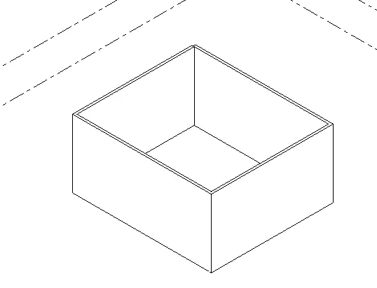
Aim : To craete a 3d view and saving the view with appropriate name
Procedure:
- Step 1: Click on view tab
- Step 2: Click on 3d view
-
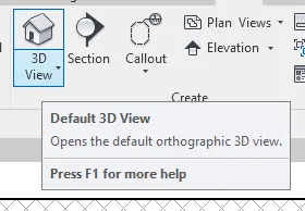
- Step 3: Click on default 3d view.
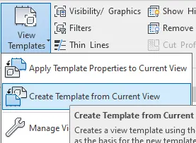
- Step 4: Click on view template and click on create template from current view.
-
- Step 5:In the new view dialogue box , insert the name as 3d view and click ok.
- Step 6:The view will be craeted and we can take the view from apply template property to current view.
Result: The 3d view is craeted and saved it by name 3d view.
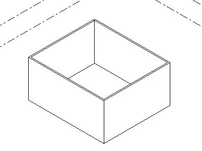
7. Navigating through view cube
Aim : To navigate with view cube and pan the model
Procedure :
Step 1:Click on the view on the view cube on the right side of the workspace.
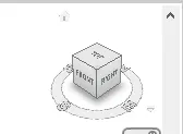
Step 2: clcik on different views
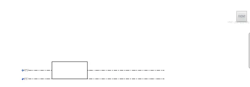
Front view
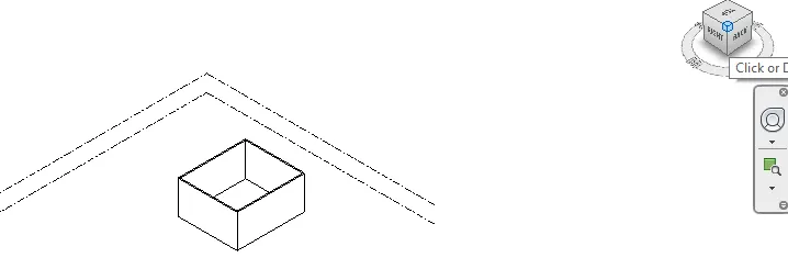
North-west view
Step 3: To pan, click on the navigation wheel below the view cube.
Step4 : click on pan option
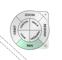
Step 5: Click on the left cursor and move the mouse to pan.
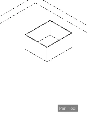
Step6: Similarly click on orbit option in the navigation wheel.
Result: Use of view cube and pan/orbit in navigation wheel is shown
8. Use of visibility settings:
Aim : To use visibility settings to switch model to shaded, realistic, hidden lines.
Procedure:
Step 1: Click on the cube at the bottom toolbar -visual style.
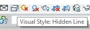
Step2: seelct the hidden line
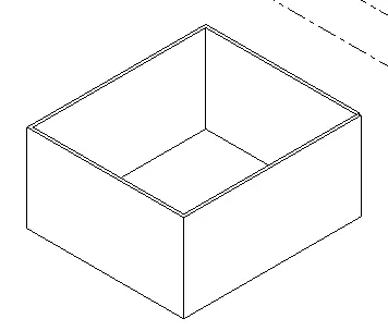
Step 3: Select shaded
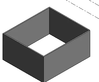
Step 4: Select realistic
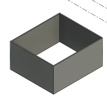
Result: Hidden lines, shaded , realistic options are done by visibility settings.
9. Use of sun path:
Aim : To on and off sunpath to view the shadings in layout
Procedure:
Step 1: Click on the icon of sun on bottom toolbar.
Step 2: Click it so that the sun path is on.
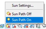
- Date and time will be visible.
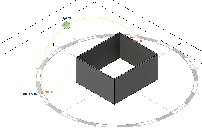
Step 3: Similarly put the sun path off
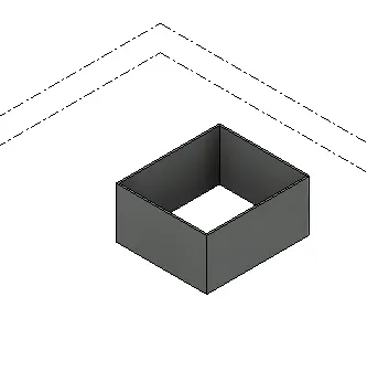
Result: Use of sunpath on / off is done.
10. Use of manage toolbar
Aim : Using manage toolbar to enter project setting, name and issue date.
Procedure:
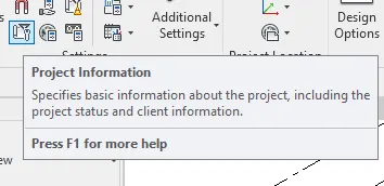
Step 1: Click on manage toolbar, click project information
Step 2: Project information dialouge box appears.
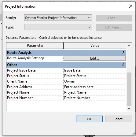
Step 3: From the other click on project issue date and give a value
Step 4: Similarly select the project name, project status, client name , project address and project number
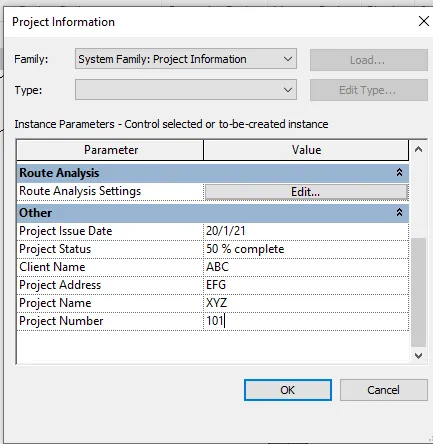
Result: By manage toolbar , project settings are changed.
11. Analyze toolbar in Rivet and its benifits

- Analyze toolbar in Rivet helps in evaluating the building performance - analyzing the model by boundary conditions, loads etc.
- It evaluates the sustainability of the model.
Benifits of analyze tool for design and modelling:
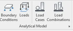
- Structural analysis it has :
-Boundary condition: we can give line and area boundary conditions to the model
-Loads: we can apply point , line and area load to the model.
-Load cases: we can add and edit the load cases
- Load combination: To add load combinations.
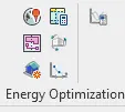
- It also helps to perform energy optimiszation and enegry analysis.
- For energy analysis it has features:
- Create energy model : This allows to inspect the energy analytical model so that we can validate it before running the energy stimulation. The enrgy analytical model is based on conceptual mass,( materials used for constructing the building,quantity and amount used in project) bulding element or both depending on the analysis mode selected in the energy setting dialogue.
- Generate: After creating energy model , it hepls to generate and evaluates the sustainability / energy efficiency of the building .
Set ranges to define envelope constructions, mechanical systems, operational shedules,and renewable insights to determine energy cost range and factor sensitivity.
- System analysis: Performs system analysis and generate report for the whole building energy stimulation and analysis.
- We will be able to understand how sustainable and energy efficient the building will be and changes we can make inorder to make it efficient.
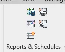
- Heating and cooling loads analysis:
- To create heating and cooling load analysis report , useful for mechanical engineers for designing ventilation ducts or heating and cooling systems.
- Rivet allows to perform analysis in multiple disciplines, so when collabrating in every discipline they can perform their own task seperately and come together as a team to show progress.
- We can achieve the progress of project together from all discipline.
12. Links in Rivet
- In insert tab links are found . It is used to link different files to the current file.
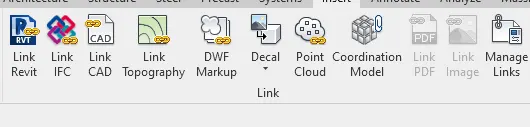
- Link rivet : It allows to link another rivet model to the current model. eg: We can link models together to specify the relative locations of individual building on a campus or to coordinate efforts across disciplines.( architectural, structural, mechanical).
- Link IFC: to link IFC file to current model to reference its information for additional design works.
- Link Cad: to link the 2d cad file to current rivet file to create 3d by rivet tools.
- Link topography: to link existing topography to the current model.
- Manage links: Provides feature to manage the links to the building models eg: If we are linking the electrical and structural model, to remove electrical from structural go to link manager and unload the model (project file) we dont want.(electrical model file).
13. Use of collabrate and its support in modelling and efficiency
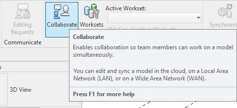
- It is the feature which helps to collaborate and help the team members to work on the model simultaneously.
- Eg: If a structural and mechanical engineer wants to work in a file simultaneously , the collaborate option creates a central file and we will have the facility to create multiple local files that enalbles collabration
- In modelling it helps the team members of different disciplines to work on the same file simultaneously.
- The efficiency of the modelling will be high , as the work can be finished faster.
- We do not have to wait for one model to be completed to start the model of next discipline.