Introduction to HEV using MATLAB and SIMULINK: DC Motor Characteristics (#05)
AIM:
This challenge aims to understand the basics of electrical components in an electric vehicle.
OBJECTIVES:
1. To study the DC machine torque-speed characteristics equations in MATLAB.
2. To understand the difference between power cables and signal cables in an electric vehicle.
3. To understand voltage levels for a battery pack of an electric vehicle.
STUDY 1:
To study the DC machine torque-speed characteristics equations in MATLAB.
DC Machine:
A DC Machine is an electro-mechanical energy conversion device. There are two types of DC machines; one is the DC generator, and another one is known as DC motor.
A DC generator converts mechanical power (ωT) into DC electrical power (EI), whereas, a DC motor converts d.c electrical power into mechanical power. The working principle of a DC machine is that current flowing through a conductor in an electric field experiences a force which produces torque (for DC motor) and a conductor moving in magnetic field results in a change of magnetic flux which results in an electromotive force (for DC generator)
The AC motor is invariably applied in the industry for conversion of electrical power into mechanical power, but at the places where the wide range of speeds and good speed regulation is required, like in the electric traction system, a DC motor is used. In applications where large quantities of DC power are required, such as electroplating, electrolysis, etc. Hence, at such places, DC generators are used to deliver power.
Construction of a DC Machine:
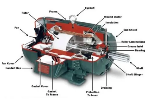
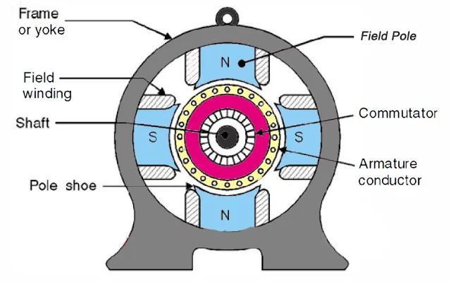
The construction of a DC machine can be done using some of the essential parts like Yoke, Pole core & pole shoes, Pole coil & field coil, Armature core, Armature winding otherwise conductor, commutator, brushes & bearings.
Rotational Speed-Torque Relation of a DC Machine:
The rotational speed of the motor can be connected to the torque with the following equation:
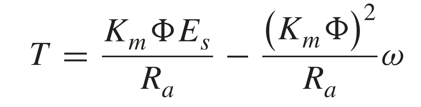
where,
TT is the torque
KmKm is the motor constant
ϕϕ is the flux associated with the coils
EsEs is the voltage supply
RaRa is the armature resistance
ωω is the angular speed
We can use this equation to find the torque produced by a motor at a given speed.
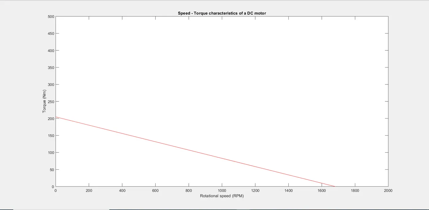
For a constant voltage supply, load 1∝1∝ speed and for a constant load, voltage ∝∝speed. Therefore, speed and torque are inversely related such that and increase in torque reduces the rotational speed giving us a linearly decreasing linear plot as shown below.
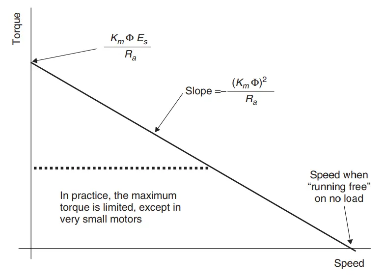
The y-intercept is the maximum torque at a nominal voltage (Stall Torque) whereas the x-intercept is the maximum speed at nominal voltage (No-Load speed)
MATLAB script file for speed-torque characterization of a DC motor:
% Using MATLAB to study speed-torque characteristics of a DC motor
clear all
close all
clc

% User inputs for motor speed constant, voltage and armature resistance
msc = input ('Enter the motor speed constant (RPM per volt) - ');
es = input ('Enter the voltage supply (volts) - ');
ra = input ('Enter the armature resistance (ohms) - ');

% Linear array for rotational speeds of motor from 0 rad/s to 2000 rad/s
omega = linspace (0,2000,2001);

% Back EMF constant (Back EMF is proportional to speed and motor speed constant is given in RPM per volt, hence unity)
eb = 1;

% Calculating the value of motor constant times phi (km * phi)
km_phi = (eb * 60)/(msc * 2 * pi);

% Calculating torque at each value of rotational speeds
T = ((km_phi * es)/ra) - (((km_phi)^2 .* omega)/ra);

% Converting rotational speeds to RPM for plotting purposes
omega_rpm = omega .* (60/(2 * pi));

% Calculating maximum current discharge when rotational speed is zero and back emf is zero;
I = (es) / ra;

% Calculating maximum torque of the motor
T_max = km_phi * I;

fprintf ('The stall\\maximum torque of the DC motor is %d\n',T_max);

% Ploting torque as a function of rotational speed
plot (omega_rpm, T , 'color', 'r');
xlabel ('Rotational speed (RPM)');
ylabel ('Torque (Nm)');
axis ([0 2000 0 500]);
title('Speed - Torque characteristics of a DC motor')
Input:

Output:

STUDY 2:
To understand the difference between power cables and signal cables in an electric vehicle.
Power Cables:
Power cables are the wires used in an electrical vehicle to transmit electrical power to and fro from the energy source. Since power cables transmit high currents, they are generally made from copper (higher volumetric electrical and thermal conductivities compared to other conductors) with nominal cross-sectional areas greater than 6 mm2mm2.
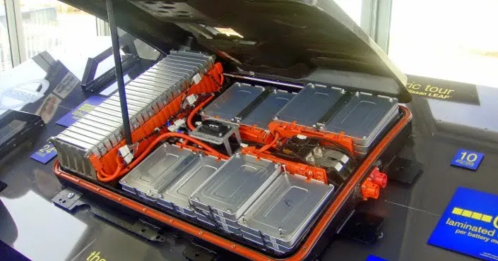
Power cables (in orange) in the battery pack of an EV
Signal Cables:
Signal cables are wires used in an electrical vehicle to transmit data and electrical signals to the components or subsystems like the powertrains, brakes, ADAS (Advanced Driver Assistance Systems), infotainment systems, etc. These wires are smaller in diameter (flexible) with lower power and current ratings (used with lower voltage ranges)
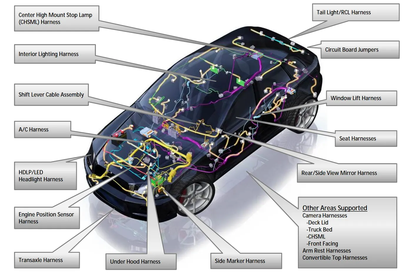
Wire harness in a conventional ICE vehicle
Distinguishing between power cables and signal cables:
- Size of the cable: Power cables are larger in diameter compared to a signal cable.
- Color of the cables: As an industry standard, power cables are orange in color.
- Cable Connections: Cables connecting the battery to the propulsion components like motor and inverters and high are power cables. Power cables can also extend to heavy electrical devices like the air conditioner.
STUDY 3:
To understand voltage levels for a battery pack of an electric vehicle.
-
Voltage, electric potential difference, electric pressure, or electric tension is the difference in electric potential between two points, which (in a static electric field) is defined as the work needed per unit of charge to move a test charge between the two points.
-
In the International System of Units, the derived unit for voltage (potential difference) is named volt. In SI units, work per unit charge is expressed as joules per coulomb, where 1 volt = 1 joule (of work) per 1 coulomb (of charge).
An electric vehicle battery is often composed of many hundreds of small, individual cells arranged in a series/parallel configuration to achieve the desired voltage and capacity in the final pack. A common pack is composed of blocks of 18-30 parallel cells in series to achieve the desired voltage. For example, a 400V nominal pack will often have around 96 series blocks (as in the Tesla Model 3).
Common nominal pack voltages in current vehicles range from 100V-200V for hybrid/plug-in hybrid vehicles and 400V to 800V and higher for electric-only vehicles. The reason for this is higher voltages allow more power to be transferred with less loss over the same diameter (and mass) of copper cable.
In the automotive industry, high-voltage refers to voltages above 60 V. When specifying vehicle voltage classes it is more useful to distinguish between low and high voltage. In this way, laypersons can easily recognize the increased risk associated with higher voltage.
The electrical performance can be increased by using higher current or voltage rates. The use of higher current rates to improve performance is determined by the system design because higher current flows require the internal and external pin contacts (power modules and connectors) and cabling to have greater cross-sectional areas. Since the current level cannot be increased above 250 A due to physical limitations, improved performance in passenger/commercial vehicles can be achieved with higher voltage rates.
The drawbacks of higher voltages include the necessity for higher-voltage-rated components in the entire system. They also prevent the ability to use DC fast-charging stations of a lower voltage without incorporating some type of DC-DC boost converter in the on-board charger.
Common battery capacity ranges, on the other hand, are as follows:
- Hybrid vehicles: 0.5 to 2 kWh
- Plug-in hybrid vehicles: 4 to 20 kWh
- Electric vehicles: 30 to 100 kWh or more.