Internship in plastic part creation using Catia V5
Project Report
(AUG 2022-NOV 22)
“Conversion of plastic component into solid with 2.5 mm
thickness”
This report is submitted in partial fulfilment of the
requirements for the award of
Master degree post graduate in
“Hybrid Electric Vehicle Design and Analysis”
Carried out and submitted by
Student Name:-Sumeet K. Joshi
Software used: - Catia V5
Under the guidance of Mr Srikanth Chikkam
Senior Associate Technical Support Engineer
Mechanical (Design)
ACKNOWLEDGEMENT
We would like to convey sincere thanks to our internal guide Mr Srikanth Chikkam, Senior Associate Technical Support Engineer, Mechanical (design) for his constant support and motivation. He mentioned our project meticulously and suggested best methods to achieve a quality project.
I wish to thank our skill Lync management for giving me this opportunity, skill Lync is constantly supporting and motivating us throughout these project.
Finally I wish to thank our family and friends for supporting us throughout the project.
Student Name
Sumeet Joshi
ABSTRACT
The process of conversion of plastic component A styled surface into solid by 2.5mm thickness involves many methods and we can create any B class and C class from the class A styled surface.
In these conversion method using Catia v5 we can convert any styles surface into solid and create a model that fits to any component which can be used in day to day life.
A styled surface created from alias software of automotive design can be used for the conversion and this conversion method solve many problems while designing and manufacturing.
CONTENTS
1) Objective
2) Surface to solid Conversion procedure
3) Main Tooling Axis
4) Class B conversion
5) Class C conversion
6) Final Trim close surface and solid part
7) Draft analysis
8) Orientation Views
9) Draft analysis orientation view
10) Core and cavity design
11) Exploded view of core and cavity
12) Conclusion
INTERN MODEL
OBJECTIVE: - TO create the solid Plastic component through the given Class-A surface, class B and class C from class A surface and to create a solid of 2.5mm thickness solid, meeting the requirements of the draft angle and at the end perform the Draft analysis on the model.
After the draft analysis of the solid component of class A , solid part we analysis the material used on the component.
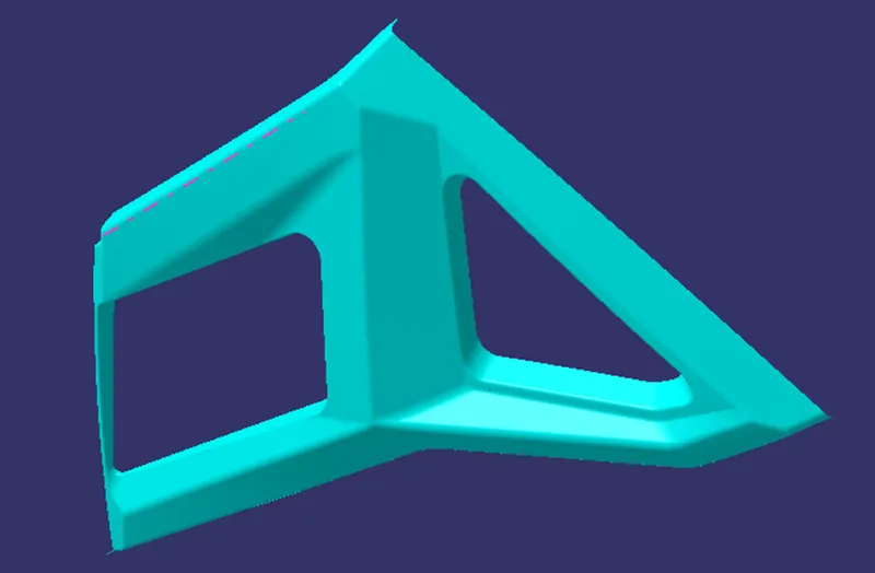
This was the provided Class A surface
Surface to solid Conversion Procedure:-
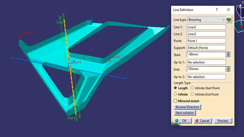
First i created the main tooling axis from the class A surface by creating the plane and intersect the surface A with the plane and created the sketch and bisect the two lines and created the main tooling axis. With the main tooling axis we can do the draft analysis in order to create the core and cavity design of the component.
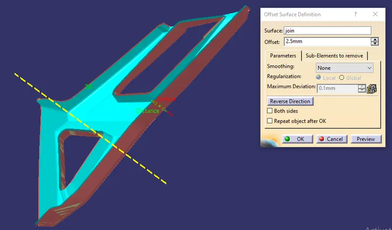
Starting from the class A surface we create the class B surface by 2.5mm offset through the sweep command that create the flange type in order to trim with the class C surface which extrapolate the class C then finally we trim both the class B and Class A&C. And check the close boundary condition and through close close surface command it is clear that body is not opened and create a solid part through close surface in part work bench. Main Tooling Axis:-
Creating the class B surface by offsetting the class A and clear all the patches that are left after the offset as shown below
After the offset of 2.5 mm from class A , clear the patch if required to give the better surface design and join all the surface and extrapolate the boundary of the class B surface to such extend that it can trim with the class C surface and final Class B surface with the main tooling axis as shown below.
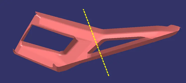
Class B
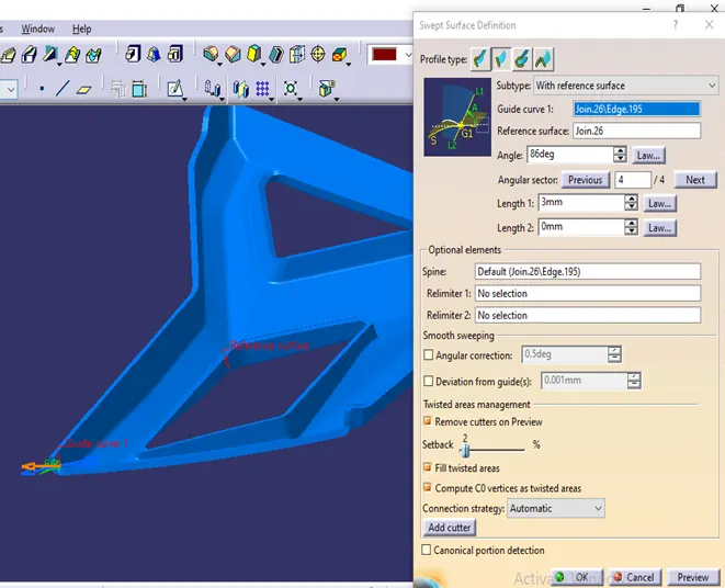
Create the class C by taking the boundary from the class A and sweep with the reference surface and created the class C as shown below.
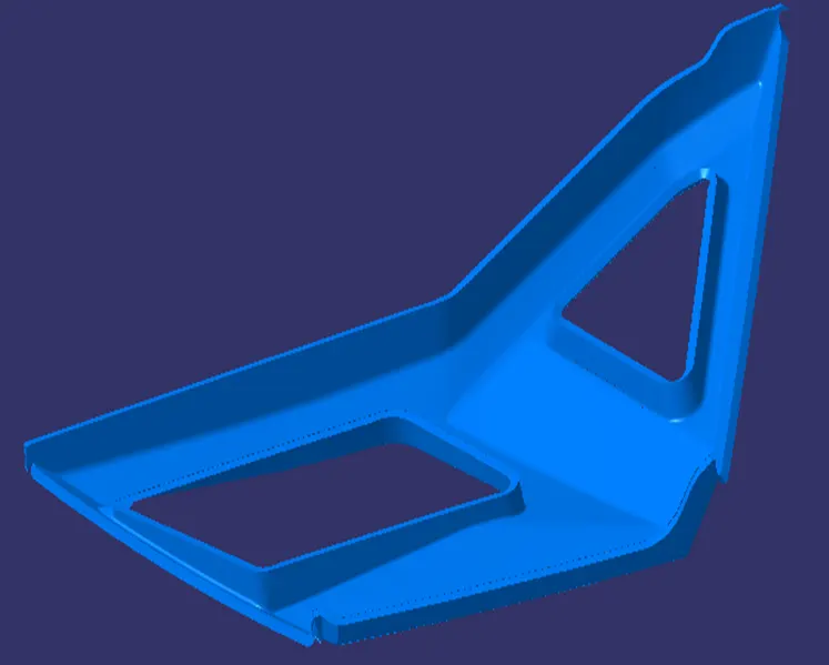
Class C
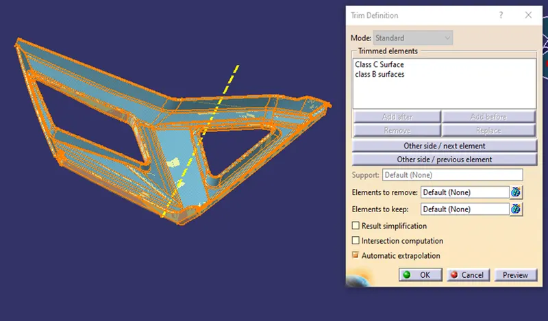
Then with the class B and the class c use the trim option and it will remove the intersect surface from the class B and Class C and create the close surface as shown below.
Checked the close boundary and checked in the part design for the close surface and created the solid part as shown below.
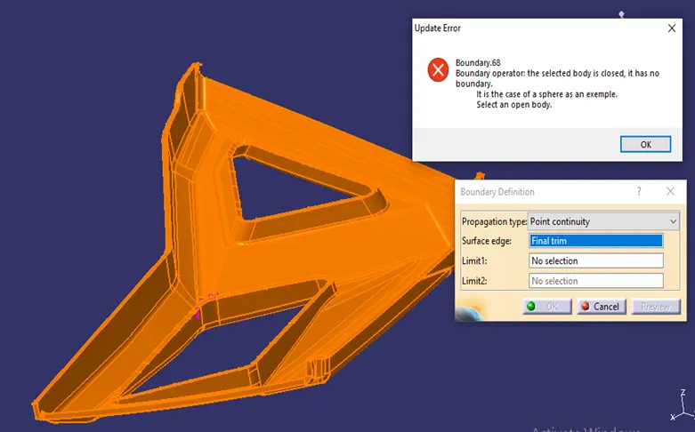
Close surface and solid part
Then created the flange for the mounting Bose of M6 tapping and finally solid model with the mounting boss of M6 is created.
Mounting boss of M6 2nos created on the flange and with the union trim option add with the main solid body and created the main solid part as shown below.
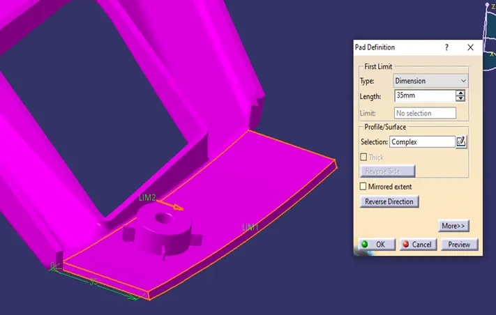
Flange
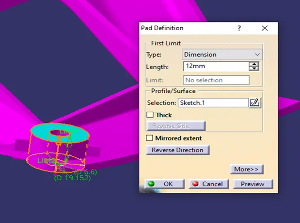
Mounting Boss M6
Using the Union Trim option I added the Mounting Boss M6 of 2 No's to the main solid part and Translate the mounting boss of M6 from point to point and created in the middle of the flange as shown below.
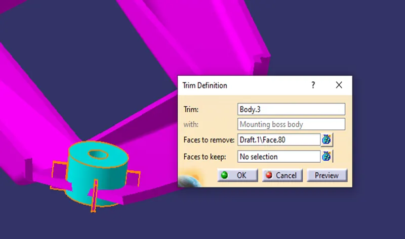
Union Trim
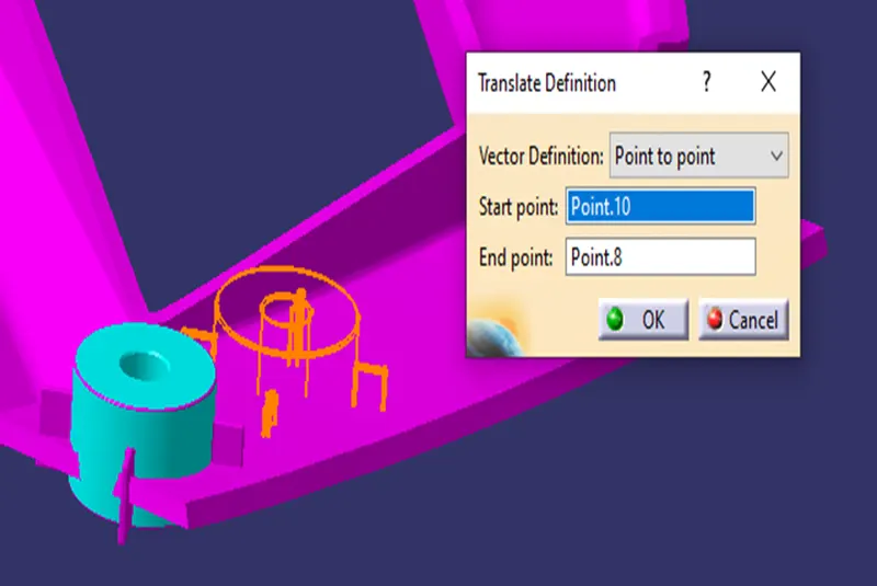
Translate Mounting Boss
Then finally created the solid model with the mounting boss of M6 as shown below
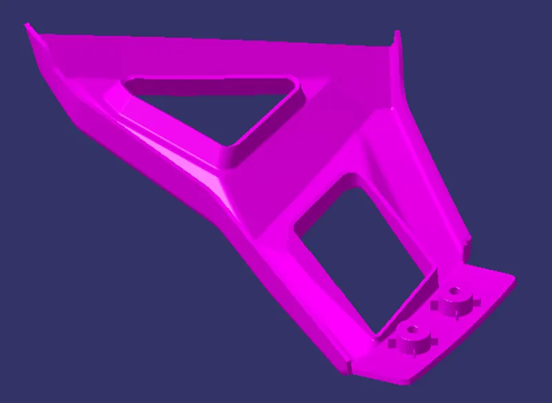
FINAL SOLID PART
Material used in the Intern model
Acrylonitrile Butadiene Styrene (ABS)
PROPERTIES
- Highly rigidity
- Good impact resistance
- Good insulating property
- It has good weldability
- Good abrasion and strain resistance
- High dimensional stability (mechanically strong
And stable overtime)
- High surface brightness
DRAFT ANALYSIS
Draft analysis is done by customize the material and using the tool option > draft analysis.
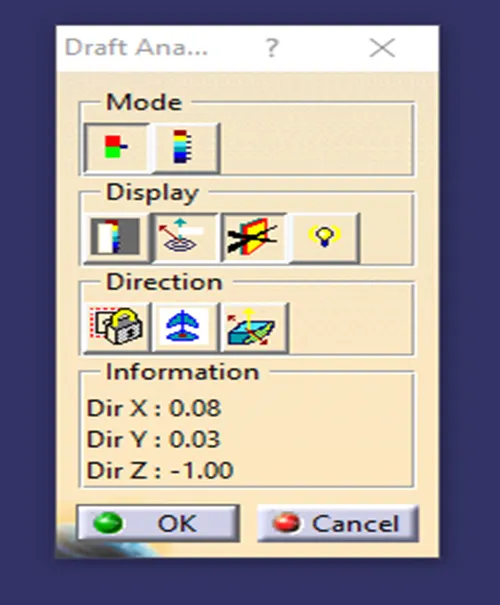
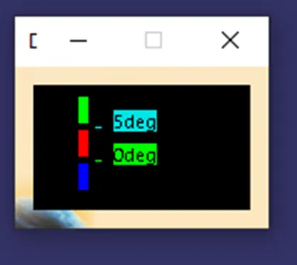
From the main tooling Axis we drag the compass to the main tooling axis and lock the orientation of the compass and analysis under the running point we move around the surface and color obtained as shown above from the dialogue box blue green and red. We analysis the draft of the model for moulding operation
Draft analysis of the Surface Intern Model
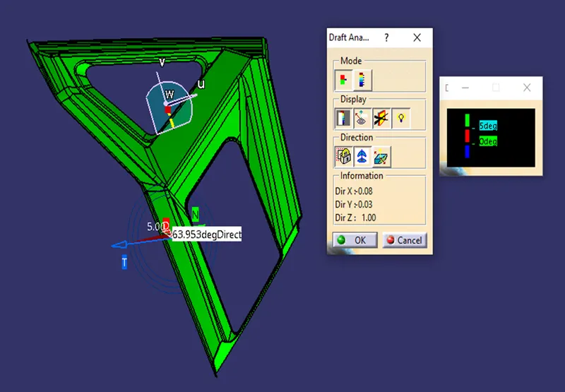
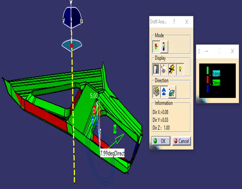
Draft Analysis of solid Intern model
Conduct the draft analysis of the following model as shown below.
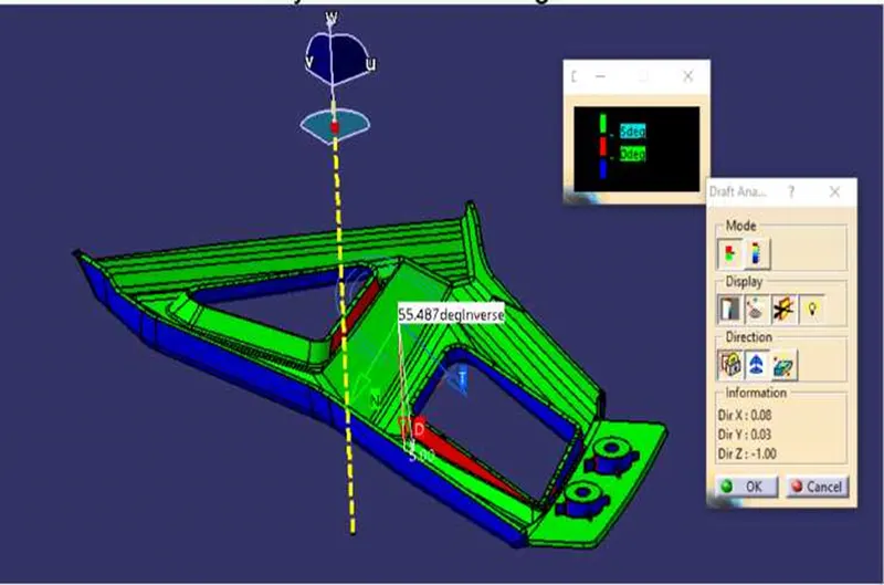
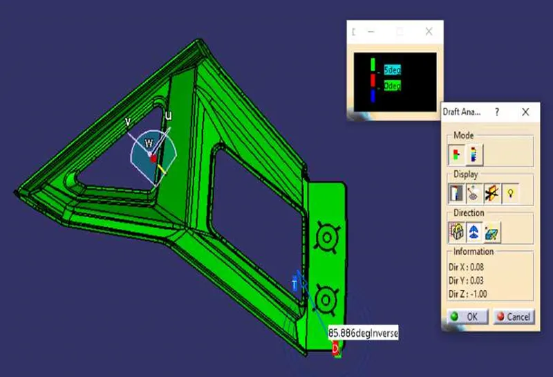
DRAFT ANALYSIS ORIENTATION VIEW
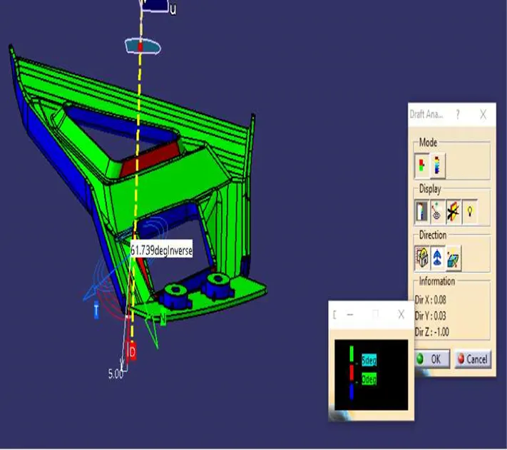
Isometric view
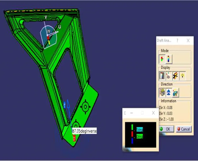
Top view
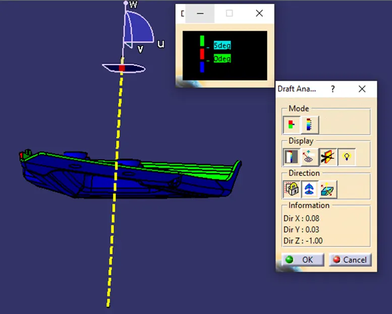
Front View
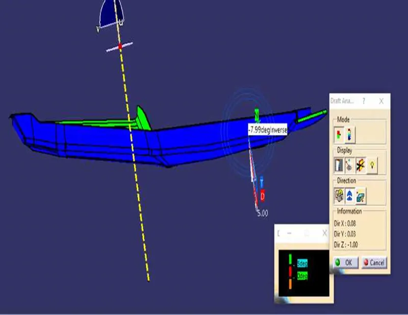
Side View
Core and Cavity Design
Procedure for Core and Cavity Design
The Intern Model is created in the Injection Moulding
Injection moulding: - Plastic injection moulding is the process of melting plastic pellets (thermosetting/ thermoplastic polymers) that once malleable enough, are injected at pressure into a mould cavity, which fills and solidifies to produce the final product.
Intern model material is ABS Acrylite Butadiene and Styrene
Core and Cavity Material – P20 mold steel – low alloy tool steel that is characterized by good toughness at moderate strength levels.
INJECTION MOULDING
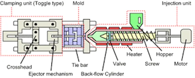
INJECTION MOULDING
Core design
First done the multiple extract from the solid body for core surface as shown below.
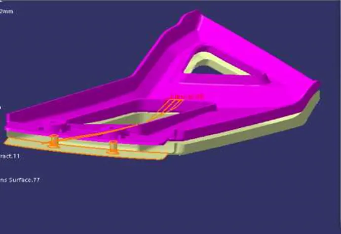
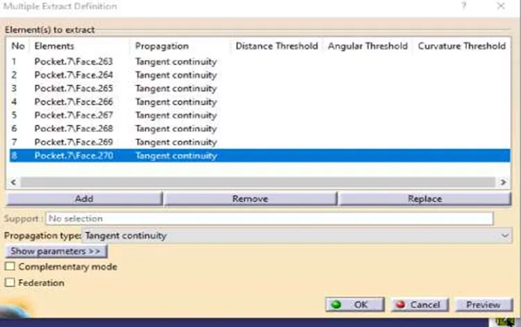
After clearing all the sweep and extrude command using sketch I extrude and done the final trim as shown below
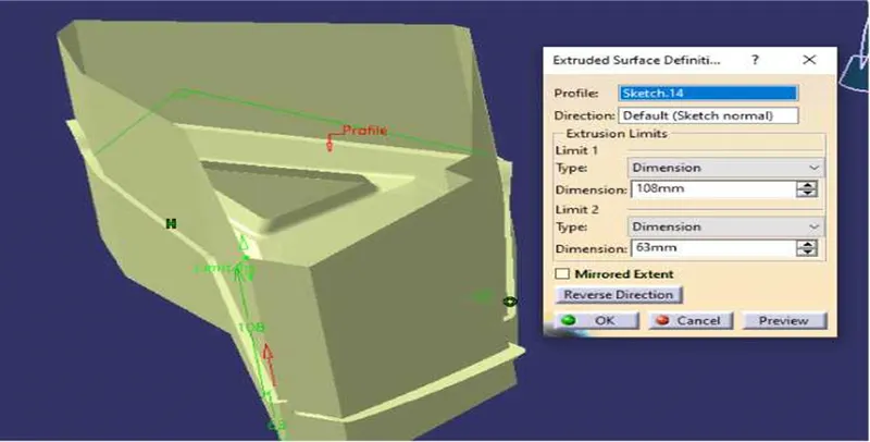
Final trim for the core design as close surface and after filling the surface I joined the surface.
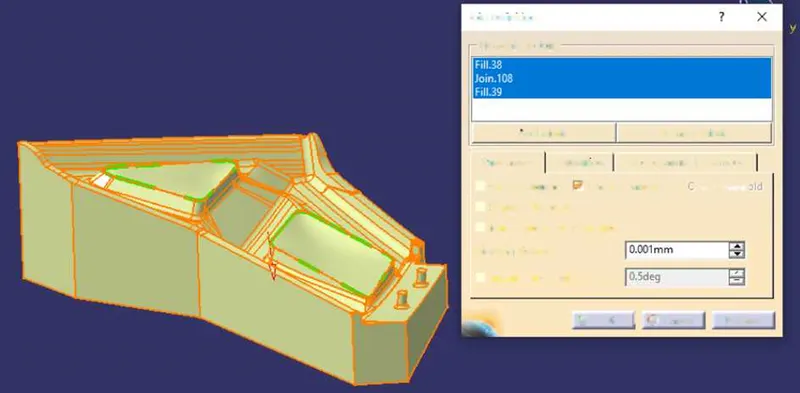
Then in the part workbench I used the close surface command and obtain the solid body as shown below
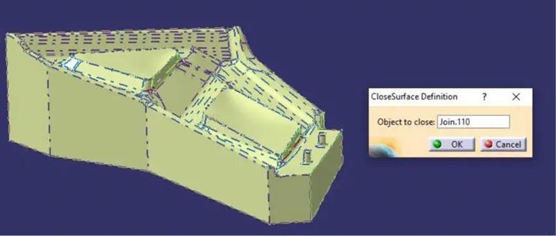
Then obtain the final Core design Body as shown below
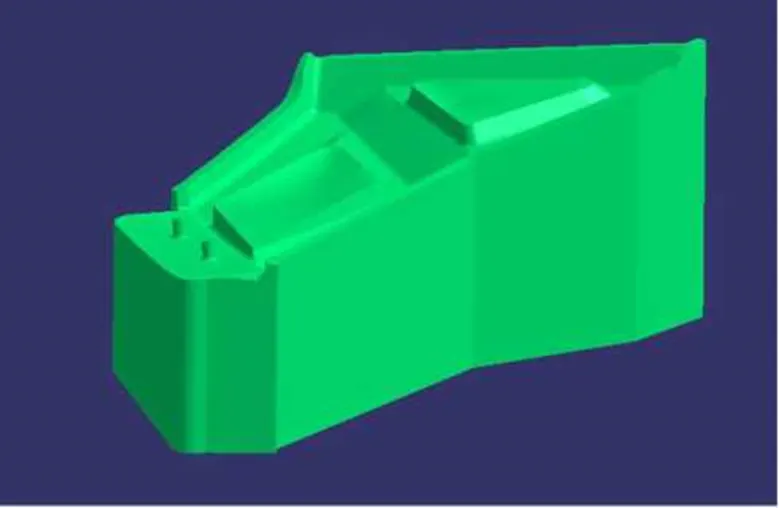
Cavity Design
First done the multiple extract from the solid body for core surface as shown below.
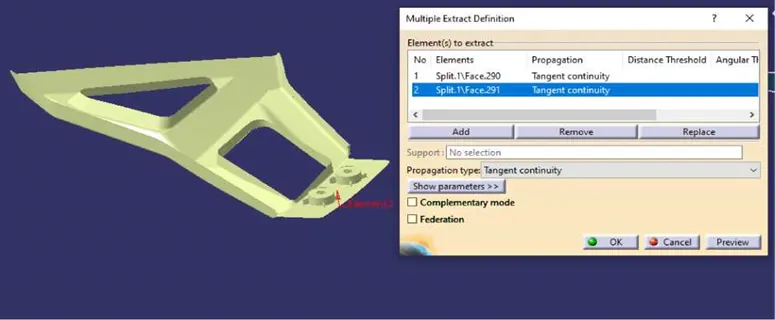
After clearing all the sweep and extrude command using sketch I extrude and done the final trim as shown below.
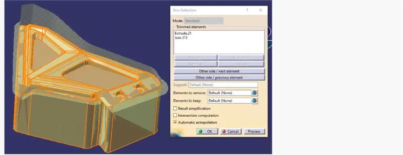
Final trim for the core design as close surface and after filling the surface I joined the surface.
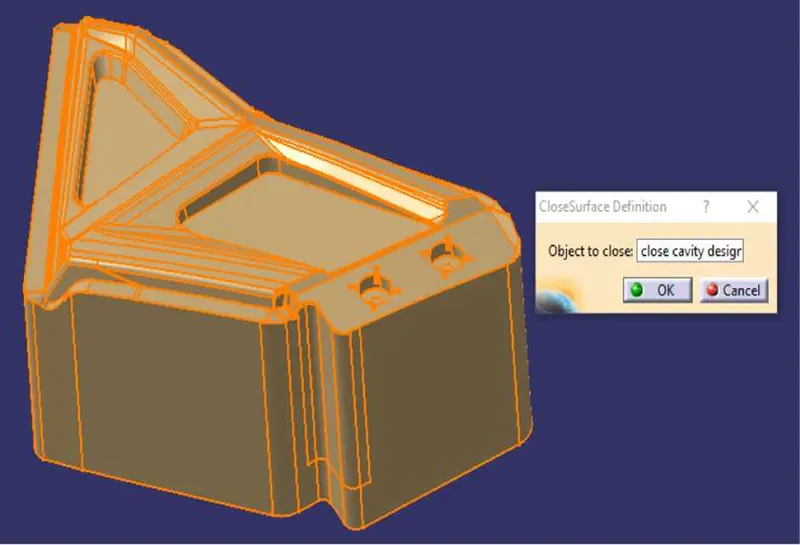
Then in the part workbench I used the close surface command and obtain the solid body as shown below
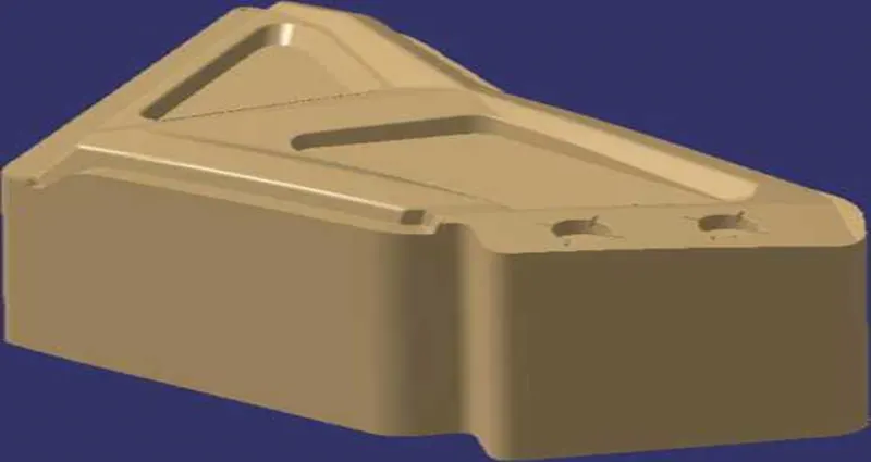
Then obtain the final core design body as shown below.
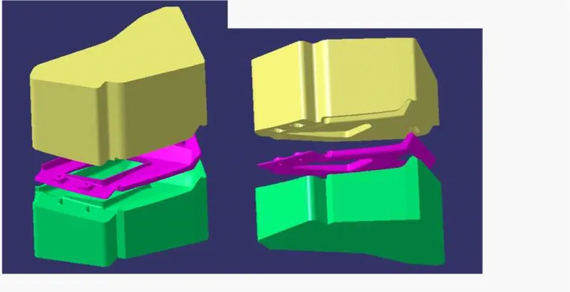
Final Core and Cavity
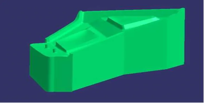
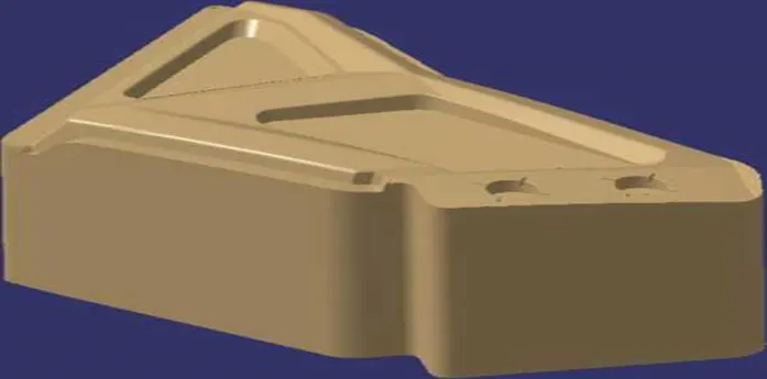
EXPLODED VIEW
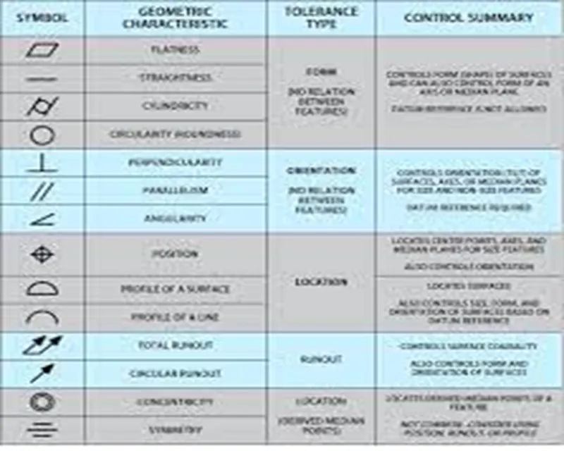
GEOMETRIC DIMENSION AND TOLERANCE
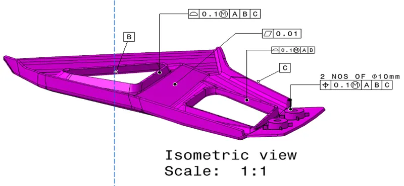
Definition: - Geometric Dimensioning and Tolerance, is a system for defining and communicating design intent and engineering tolerances that helps engineers and manufacturers optimally control variations in manufacturing processes.
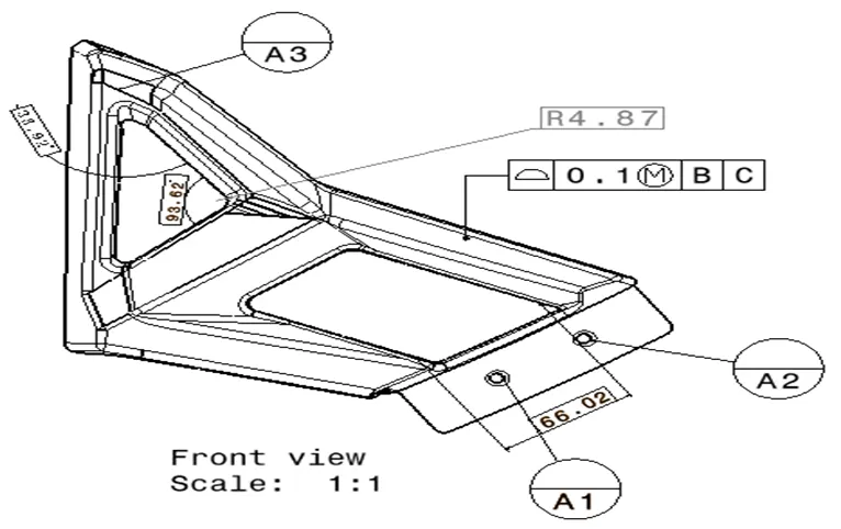
Geometric dimension and tolerance applied to the model in the drafting option and obtained the final result as shown below.
CONCLUSION:-
Finally created the class B and class C from the class A and created the close surface Intern model and done the draft analysis and gave the orientation view
Project report
SUMEET JOSHI
THANK YOU