Internal Geneva Mechanism
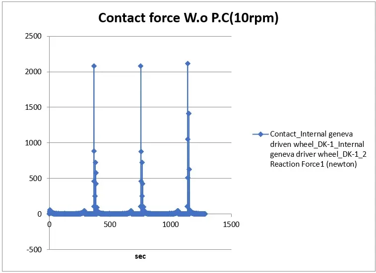
The above shown chart gives analytical data of contact force vs time between the driver and driven wheel of an internal Geneva mechanism. Contact force refers to the force exerted between the driving wheel and the driven wheel during the engagement and disengagement phases of the Geneva mechanism. This chart shows how a steel driver wheel having input speed of 10rpm reacts with the driven wheel made up of same material in dry condition (without any lubrication). The spikes in the chart shows that a reaction force of 2114 N is created uniformly in a time interval of every 6 secs during the engagement of driver & driven wheels.
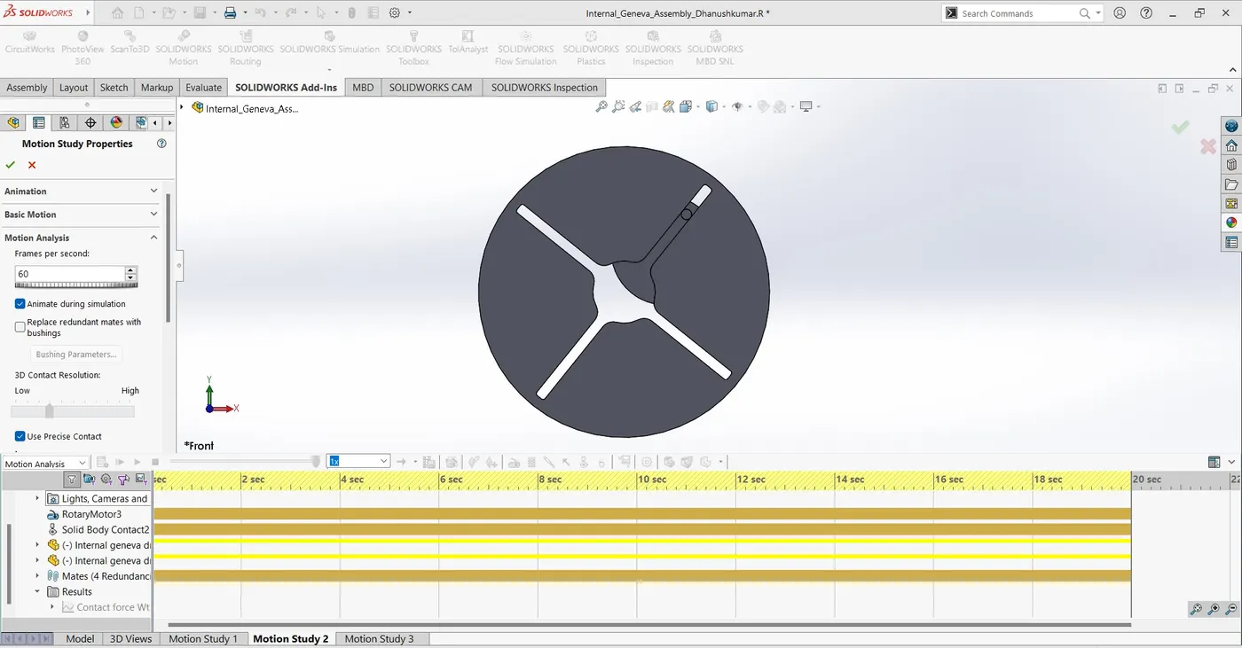
This picture shows the precise contact was established between the driver & driven wheels.
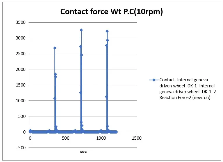
The above shown chart gives analytical data of contact force vs time between the driver and driven wheel of an internal Geneva mechanism. Contact force refers to the force exerted between the driving wheel and the driven wheel during the engagement and disengagement phases of the Geneva mechanism. This chart shows how a steel driver wheel having input speed of 10rpm reacts with the driven wheel made up of same material in dry condition (without any lubrication) with precise contact. The spikes in the chart shows that a reaction force of 3256 N is created uniformly in a time interval of every 6 secs during the engagement of driver & driven wheels.
By comparing the above charts, we can conclude that using the precise contact option will give us the exact reaction force created during the engagement and disengagement of the driver and driven wheels.
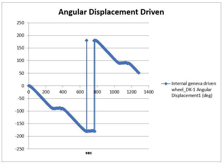
The above shown chart gives analytical data of angular displacement vs time of the driven wheel of an internal Geneva mechanism.The angular displacement in a driven wheel of an internal Geneva mechanism refers to the amount of rotation that the driven wheel undergoes during its operation. In a Geneva mechanism, the driven wheel experiences intermittent or discrete angular displacements, which are associated with the engagement and disengagement of the driving pin with the slots in the driven wheel. The spike in this chart shows an angular displacement of 180 degree for an input speed of 10rpm.
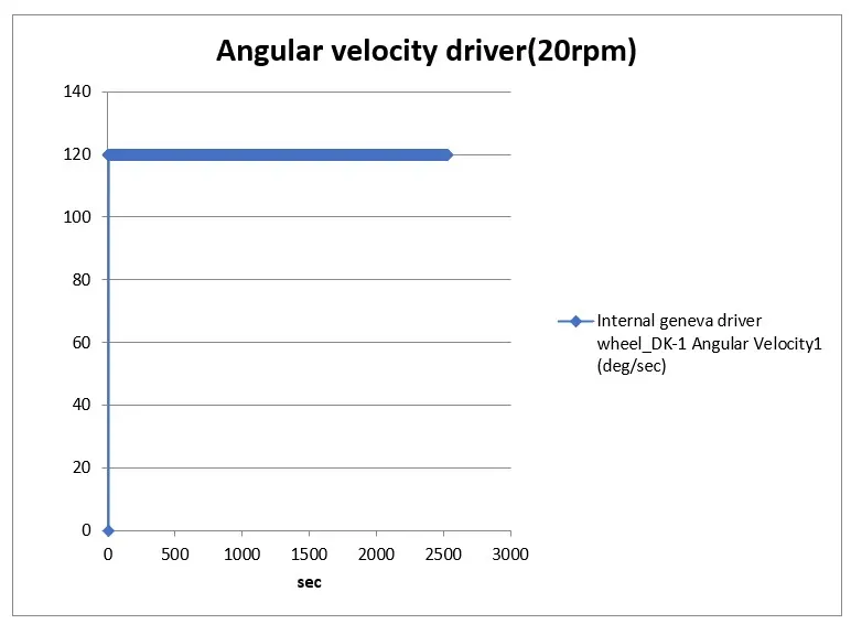
The above shown chart gives analytical data of angular velocity vs time of the driver wheel of an internal Geneva mechanism. The angular velocity in the driver wheel of an internal Geneva mechanism refers to the rate at which the driver wheel rotates. The Geneva mechanism produces intermittent rotary motion, and measuring the angular velocity is important for several reasons. The measured angular velocity is crucial for controlling the motion of the driver wheel. By adjusting the angular velocity, we can optimize the speed and precision of the mechanism's operation to suit specific application requirements. For, the given input speed of 20rpm produces the angular velocity of 120 deg/sec constantly.
MOTION ANALYSIS OF INTERNAL GENEVA MECHANISM
Objective:
The main objective of this project is to conduct a motion study for dynamic visualization, identification of timing and synchronization issues, study of contact force, angular displacement and angular velocity of an “Internal Geneva Mechanism” and compare the results to optimize the design using the Solidworks CAD tool.
Description:
Internal Geneva Mechanism:
The internal Geneva mechanism is a type of intermittent motion mechanism used in machinery to provide periodic rotational motion. It typically consists of two main components: a driving wheel and a driven wheel. The driving wheel has a pin that engages with slots in the driven wheel. During the rotation of the driving wheel, the pin engages with the slots, causing the driven wheel to rotate intermittently. The internal Geneva mechanism comprises of two components.
· Driver or Driving wheel, and
· Driven wheel.
Driving Wheel: Contains a pin that engages with the slots in the driven wheel.
Driven Wheel: Has slots that interact with the pin on the driving wheel.
These parts produce intermittent, step-by-step motion as the pin engages and disengages with the slots.
Working Principle:
Usually, the driver or driving wheel connected with an input power to start the operation and continue. While the input power was given to the driver wheel, the pin it engages and disengages with driven wheel.
· Engagement: As the driving wheel rotates, the pin engages with a slot in the driven wheel, causing it to rotate.
· Disengagement: After a partial rotation, the pin disengages from the slot, and the driven wheel pauses until the next engagement.
Applications:
Internal Geneva mechanism was used in the following applications,
· Indexing Mechanisms: Used in machines where precise indexing or positioning is required, such as in rotary tables for machining operations.
· Conveyor Systems: Applied in conveyor systems for intermittent movement of products along the production line.
Motion Analysis:
Motion analysis is the process of studying the movement of objects or systems over time. It involves analysing the position, velocity, and acceleration of objects to understand their dynamic behaviour. This analysis can be conducted through mathematical calculations, computer simulations, or experimental measurements, depending on the complexity of the system. Motion analysis in mechanical engineering involves the study and evaluation of the movement of mechanical components and systems. This analysis is essential for understanding, optimizing, and designing mechanical systems to ensure proper functionality, efficiency, and safety.
It employs tools such as computer-aided design (CAD) software, simulations, mathematical models, and experimental testing to gain insights into the behaviour of mechanical systems. It is an integral part of the design and optimization process, enabling engineers to create efficient, reliable, and well-performing mechanical systems.
Design and Assembly:
The driving and driven wheels were designed by creating 2D drawings as per the requirement and design parameters, then converting those sketches into 3D parts or components using available features in the solidworks.
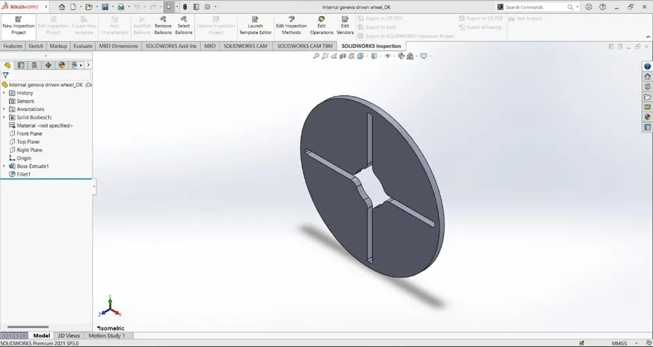
This picture shows the part design of a driven wheel.
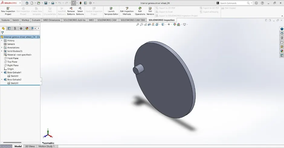
This picture shows the part design of a driven wheel.
After creating the part files, they were inserted into the assembly workbench and assembled them using relevant mates without arresting all degrees of freedom. Because, Internal Geneva mechanism needs the components to rotated about the axes.
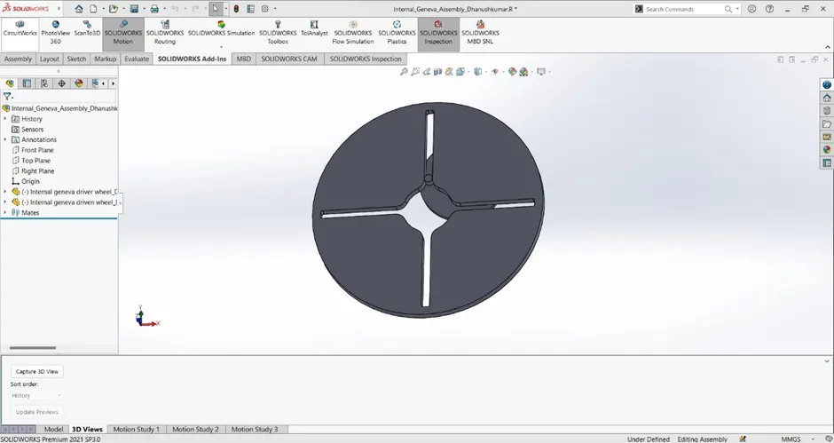
This picture shows the parts design assembled to form the internal geneva mechanism.
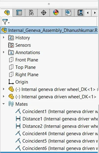
This picture shows the mates applied in the internal geneva mechanism assembly.
Analysis:
For this project the following conditions were consider for motion analysis,
· Material: steel on dry condition.
· Input speed: 10 rpm & 20 rpm.
· Data for comparison: Contact force (with & without precie contact), Angular displacement and Angular velocity v/s time.
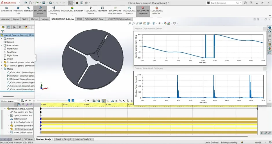
This picture shows the motion study of contact force without precise contact vs time of driver and driven wheels, and Angular displacement of driven wheel at 10 rpm.
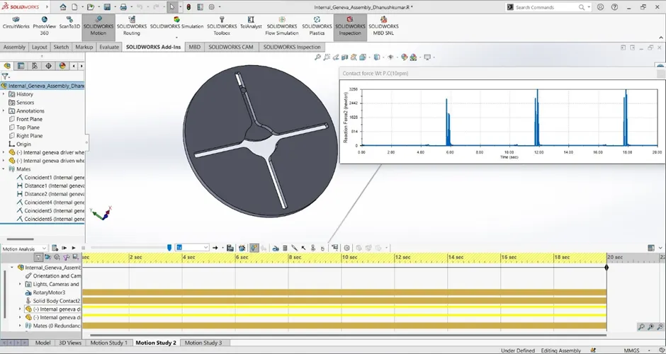
This picture shows the motion study of contact force with precise contact vs time of driver and driven wheels.
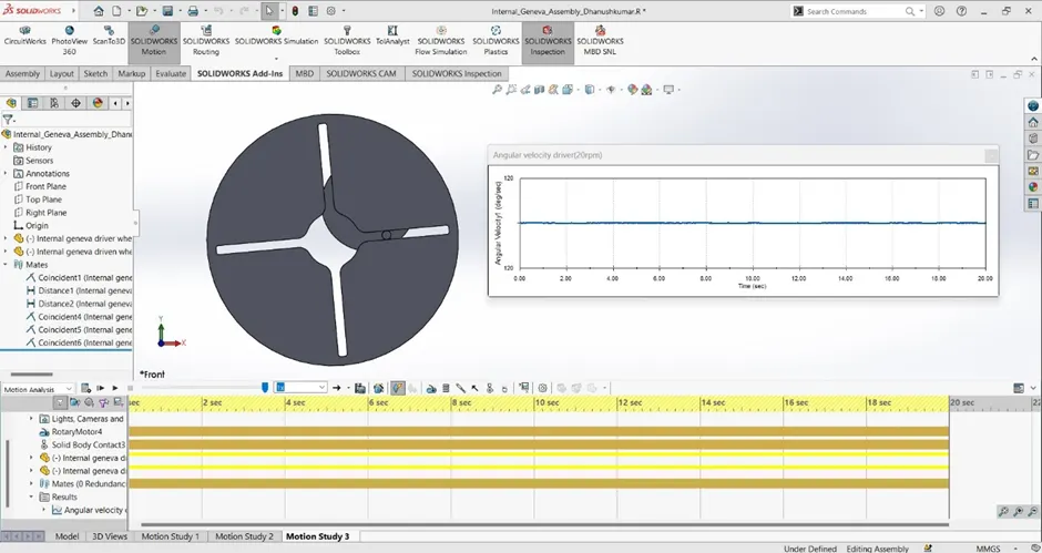
This picture shows the motion study of angular velocity vs time of driver wheel.
With the help of these data, the following comparison was done and the results were obtained.
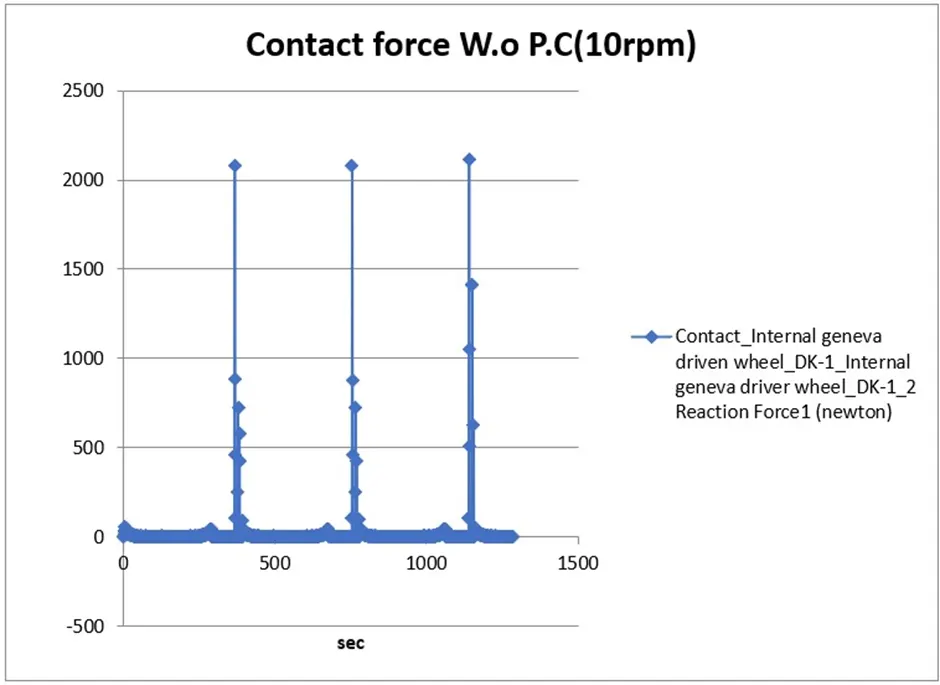
The above shown chart gives analytical data of contact force vs time between the driver and driven wheel of an internal Geneva mechanism. Contact force refers to the force exerted between the driving wheel and the driven wheel during the engagement and disengagement phases of the Geneva mechanism. This chart shows how a steel driver wheel having input speed of 10rpm reacts with the driven wheel made up of same material in dry condition (without any lubrication). The spikes in the chart shows that a reaction force of 2114 N is created uniformly in a time interval of every 6 secs during the engagement of driver & driven wheels.
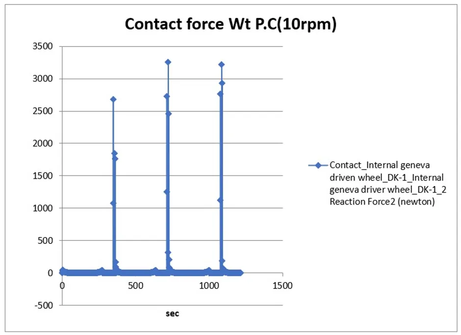
The above shown chart gives analytical data of contact force vs time between the driver and driven wheel of an internal Geneva mechanism. Contact force refers to the force exerted between the driving wheel and the driven wheel during the engagement and disengagement phases of the Geneva mechanism. This chart shows how a steel driver wheel having input speed of 10rpm reacts with the driven wheel made up of same material in dry condition (without any lubrication) with precise contact. The spikes in the chart shows that a reaction force of 3256 N is created uniformly in a time interval of every 6 secs during the engagement of driver & driven wheels.
By comparing the above charts, we can conclude that using the precise contact option will give us the exact reaction force created during the engagement and disengagement of the driver and driven wheels.
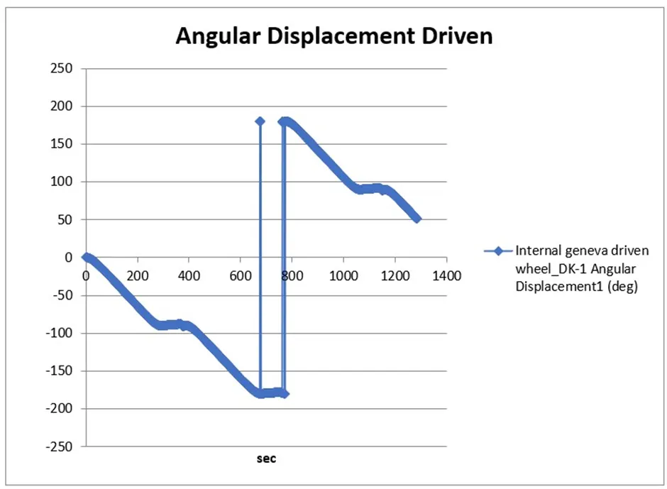
The above shown chart gives analytical data of angular displacement vs time of the driven wheel of an internal Geneva mechanism.The angular displacement in a driven wheel of an internal Geneva mechanism refers to the amount of rotation that the driven wheel undergoes during its operation. In a Geneva mechanism, the driven wheel experiences intermittent or discrete angular displacements, which are associated with the engagement and disengagement of the driving pin with the slots in the driven wheel. The spike in this chart shows an angular displacement of 180 degree for an input speed of 10rpm.
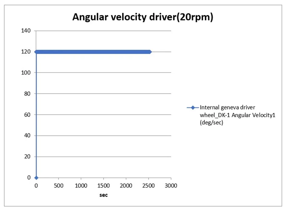
The above shown chart gives analytical data of angular velocity vs time of the driver wheel of an internal Geneva mechanism. The angular velocity in the driver wheel of an internal Geneva mechanism refers to the rate at which the driver wheel rotates. The Geneva mechanism produces intermittent rotary motion, and measuring the angular velocity is important for several reasons. The measured angular velocity is crucial for controlling the motion of the driver wheel. By adjusting the angular velocity, we can optimize the speed and precision of the mechanism's operation to suit specific application requirements. For, the given input speed of 20rpm produces the angular velocity of 120 deg/sec constantly.
Conclusion:
The motion analysis of ‘Internal Geneva Mechanism’ were done, its data obtained from various inputs were analysed and compared. With all this we can conclude that the dynamics was understood.