Internal Geneva Mechanism
AIM :
- Create 3D models for driver and driven wheels.
- Perform motion analysis by rotating the driver wheel at 10 rpm and 20 rpm.
- Obtain the following plots:
Contact force (between driving and driven wheel) as a function of time.
Angular displacement of the driven wheel.
- Compare the contact forves with and without precise contact and export the results that you get to excel and make the plots over there.
THEORY :
The Geneva drive is also called as Maltese cross mechanism.The Geneva mechanism translates a continious rotation into a intermittent rotary motion.The rotating drive wheel has a pin that reaches into the slot of driven wheel.
There are three basic types of geneva mechanisms namely external,internal and spherical.The speherical geneva mechanism is very rarely used. In the simplest form,the driven wheel has four slots and hence for each rotation of drive wheel it advances by one step of 90 deg. If the driven wheel has n slots it advances by 360/n per full rotation of drive wheel.
In an internal geneva drive the axis of the drive wheel of the internal drive is supported on only one side.The angle by which the drive wheel has to rotate to effect one step rotation of the driven wheel is always smaller than 180 deg in an exterval geneva and is always greater than 180 deg in an internal geneva. The external form is the more common as it can be built smaller and can withstand higer mechanical stresses.
Geneva mechanisms can be used for light and heavy duty applications. impact is a problem and it can be reduced by designing the pin in such a way that the pin in such a way that pin picks up the driven member as slowly as possible.
FLOW OF PROJECT :
- Create 3D models for driver and driven wheels on the basics of 2D drawings provided.
- Assemble the CAD models using proper constraints.
- Use the assembly in the motion analysis and set-up the motion parameters like rpm, materials etc
- Run the calculation.
- Save the animation.
- plot graphs and export to excel.
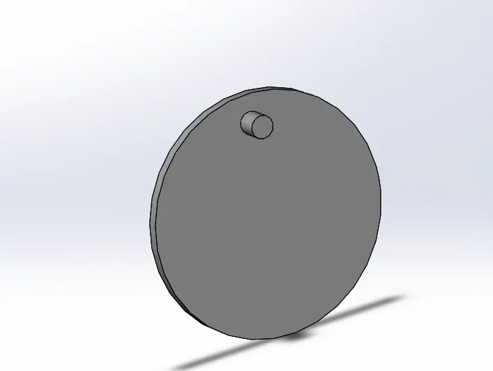
DRIVER WHEEL CAD MODEL
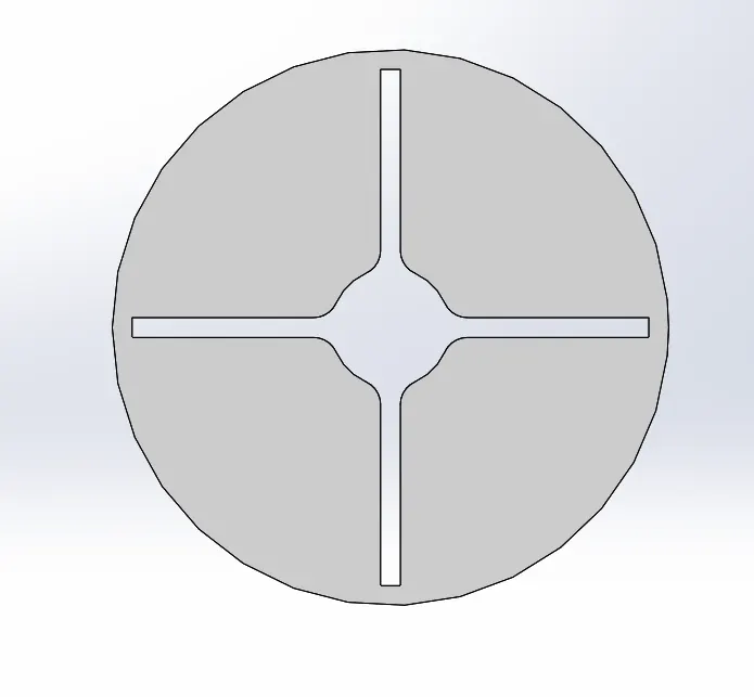
DRIVEN WHEEL CAD MODEL
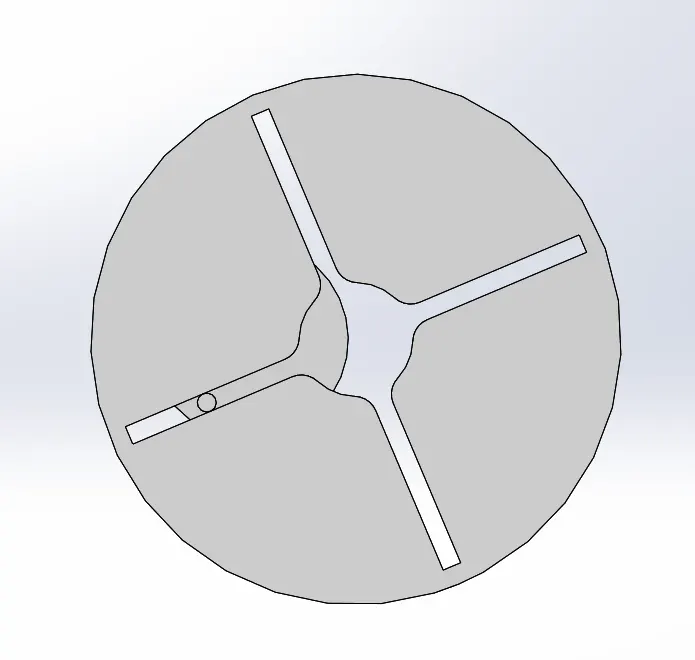
FINAL ASSEMBLY PART
MOTION STUDY SETUP:
- Intially the 2D drawings were used to make 3D CAD models of the geneva mechanism parts namely driving wheel and driven wheel.
- Those parts were imported to a new assembly and assembly was made. Both the parts were constrained to a certain degree so as to allow required degree of freedom for circular motion.
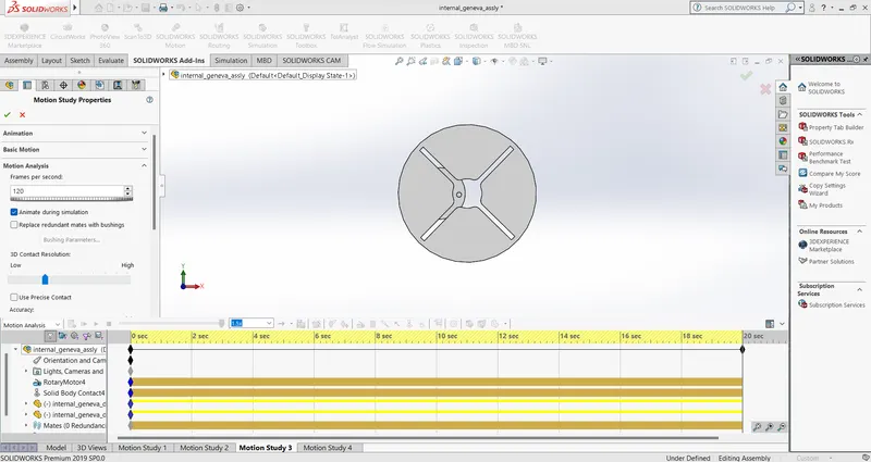
- A new motion study having type as Motion analysis was selected.
- Driving wheel was given a rotation of 10 RPM and contact between driving and driven wheel was established assuming steel(Dry) for both parts.
- In motion settings Frames per second was set to 60.
- Finally the solver of solidworks calculated the study and simulation video and reults are plotted.
- The same process was repeated for 20RPM and 120 frame per second.
60 FPS validation for Motor @10 RPM.
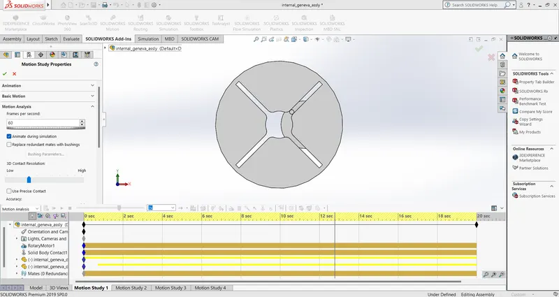
120 FPS validation for Motor @20 RPM.
Observations and conclusions
Contact forces with and without precision for 10 and 20 RPM
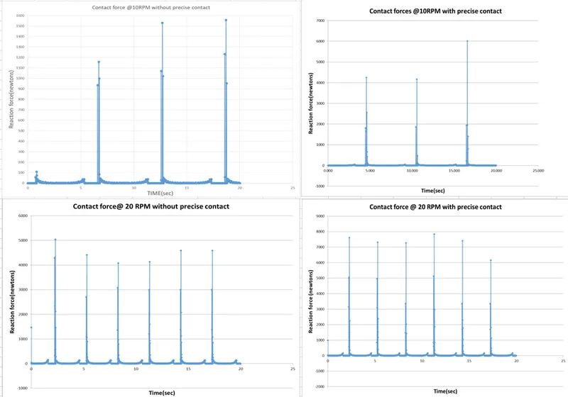
From the this graph we can point out few things
- For 10 RPM contact force with precision contact is higher than contact force without precision contact.
- For 20RPM contact force without precion contact is lower than contact force with precision contact.
- From the above graphs it is clear that as RPM values increases the contact forces also increases.
Angular displacement of driven wheel
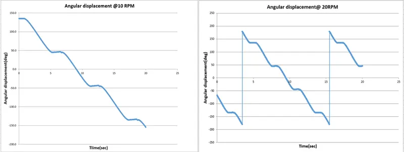
- From the above graph it is clearly stated that when the driver wheel mates the driven wheel the angular displacement occurs and stops after it reaches 90 degree.
- As driver wheel mates with driven wheel the angular displacement occurs and stops after it reaches 90 degree.
Animation link :
Conclusion:
From the given 2D draft 3D models were made and motion analysis is performed with given motor RPM specifications and FPS few conclusions were made out of it.As the frames per second increases in the motion analysis clarity on the graph also increases. As motor RPM increases the contacting forces also increases.